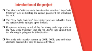
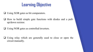
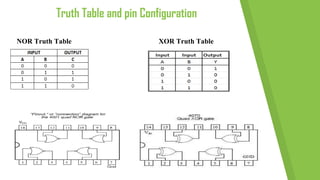
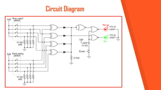
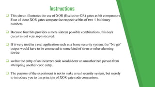
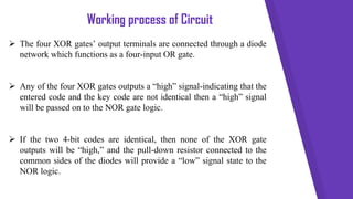
Security System Using
XOR and NOR Gates.
2
Department of Electronics and Communication
Engineering
Course Name: Digital Electronics
Course Code: ETE/ICE 311
Group No: 04
Project Name: Security System Using XOR and NOR
Member:
Burhan Uddin Shakil; ID: 2017-1-55-003
Imtiaz Ahmed Emon; ID: 2017-1-55-004
Sourav Bhattacharje; ID: 2016-1-55-013
Content
 Introduction of the project.
 Learning Objective.
 Importance and need of our project.
 Truth Table and pin Configuration.
 Circuit Diagram.
 Instructions.
 Working process of Circuit.
 Conclusion
 The idea is of this system is that the 4 bit switches “Key Code
Switches” acts as holding the correct password for unlocking
the lock.
 The “Key Code Switches” have static value and is hidden from
the person who is trying to open the lock.
 If a person who try to unlock by the wrong code kept static at
the “Key Code Switches” then the red LED is light up and then
the alarming is going on for this situation.
 We made this security system by XOR, NOR gate and other
elements because it is easy to maintain by these.
Introduction of the project
Learning Objective
 Using XOR gates as bit comparators.
 How to build simple gate functions with diodes and a pull-
up/down resistor.
 Using NOR gates as controlled inverters.
 Using relay which are generally used to close or open the
circuit manually.
6
Importance and need of our
project.
o People use password to protect their
system.
o So for protect any type of system we can
use Password Security System (using
NOR & XOR).
o This system is not expensive so we can
use it many place like office, home
security system, locker etc.
Truth Table and pin Configuration
NOR Truth Table XOR Truth Table
Circuit Diagram
 This circuit illustrates the use of XOR (Exclusive-OR) gates as bit comparators.
Four of these XOR gates compare the respective bits of two 4-bit binary
numbers.
 Because four bits provides a mere sixteen possible combinations, this lock
circuit is not very sophisticated.
 If it were used in a real application such as a home security system, the “No go”
output would have to be connected to some kind of siren or other alarming
device
 so that the entry of an incorrect code would deter an unauthorized person from
attempting another code entry.
 The purpose of the experiment is not to make a real security system, but merely
to introduce you to the principle of XOR gate code comparison.
Instructions
Working process of Circuit
 The four XOR gates’ output terminals are connected through a diode
network which functions as a four-input OR gate.
 Any of the four XOR gates outputs a “high” signal-indicating that the
entered code and the key code are not identical then a “high” signal
will be passed on to the NOR gate logic.
 If the two 4-bit codes are identical, then none of the XOR gate
outputs will be “high,” and the pull-down resistor connected to the
common sides of the diodes will provide a “low” signal state to the
NOR logic.
The NOR gate logic performs
o Prevent either of the LEDs from turning on if the “Enter”
pushbutton is not pressed.
o Only when this pushbutton is pressed can either of the LEDs
energize.
o If the Enter switch is pressed and the XOR outputs are all “low,”
the “Go” LED will light up, indicating that the correct code has
been entered.
o If the Enter switch is pressed and any of the XOR outputs are
“high,” the “No go” LED will light up, indicating that an incorrect
code has been entered.
 In this project, we will locate the two switches on breadboards, acts as
holding the correct password for unlocking the lock.
 we are used sound buzzer for alarming situation.
 Here we used to another element of one 6v relay because we need to
show something will be open, that’s why we used DC motor.
 The relay can be defined as a switch which are generally used to close
or open the circuit manually.
 From this project we can learn how we made a security system by
using XOR, NOR gate and other elements.
Conclusion
https://www.allaboutcircuits.com/te
xtbook/experiments/chpt-7/simple-
combination-lock/
https://www.slideshare.net/FatimaQay
yum1/security-system-using-xor-nor
Reference
Place your screenshot
here
14
Security System Using XOR gate NOR gate.

Security System Using XOR gate NOR gate.

  • 1.
  • 2.
    2 Department of Electronicsand Communication Engineering Course Name: Digital Electronics Course Code: ETE/ICE 311 Group No: 04 Project Name: Security System Using XOR and NOR Member: Burhan Uddin Shakil; ID: 2017-1-55-003 Imtiaz Ahmed Emon; ID: 2017-1-55-004 Sourav Bhattacharje; ID: 2016-1-55-013
  • 3.
    Content  Introduction ofthe project.  Learning Objective.  Importance and need of our project.  Truth Table and pin Configuration.  Circuit Diagram.  Instructions.  Working process of Circuit.  Conclusion
  • 4.
     The ideais of this system is that the 4 bit switches “Key Code Switches” acts as holding the correct password for unlocking the lock.  The “Key Code Switches” have static value and is hidden from the person who is trying to open the lock.  If a person who try to unlock by the wrong code kept static at the “Key Code Switches” then the red LED is light up and then the alarming is going on for this situation.  We made this security system by XOR, NOR gate and other elements because it is easy to maintain by these. Introduction of the project
  • 5.
    Learning Objective  UsingXOR gates as bit comparators.  How to build simple gate functions with diodes and a pull- up/down resistor.  Using NOR gates as controlled inverters.  Using relay which are generally used to close or open the circuit manually.
  • 6.
    6 Importance and needof our project. o People use password to protect their system. o So for protect any type of system we can use Password Security System (using NOR & XOR). o This system is not expensive so we can use it many place like office, home security system, locker etc.
  • 7.
    Truth Table andpin Configuration NOR Truth Table XOR Truth Table
  • 8.
  • 9.
     This circuitillustrates the use of XOR (Exclusive-OR) gates as bit comparators. Four of these XOR gates compare the respective bits of two 4-bit binary numbers.  Because four bits provides a mere sixteen possible combinations, this lock circuit is not very sophisticated.  If it were used in a real application such as a home security system, the “No go” output would have to be connected to some kind of siren or other alarming device  so that the entry of an incorrect code would deter an unauthorized person from attempting another code entry.  The purpose of the experiment is not to make a real security system, but merely to introduce you to the principle of XOR gate code comparison. Instructions
  • 10.
    Working process ofCircuit  The four XOR gates’ output terminals are connected through a diode network which functions as a four-input OR gate.  Any of the four XOR gates outputs a “high” signal-indicating that the entered code and the key code are not identical then a “high” signal will be passed on to the NOR gate logic.  If the two 4-bit codes are identical, then none of the XOR gate outputs will be “high,” and the pull-down resistor connected to the common sides of the diodes will provide a “low” signal state to the NOR logic.
  • 11.
    The NOR gatelogic performs o Prevent either of the LEDs from turning on if the “Enter” pushbutton is not pressed. o Only when this pushbutton is pressed can either of the LEDs energize. o If the Enter switch is pressed and the XOR outputs are all “low,” the “Go” LED will light up, indicating that the correct code has been entered. o If the Enter switch is pressed and any of the XOR outputs are “high,” the “No go” LED will light up, indicating that an incorrect code has been entered.
  • 12.
     In thisproject, we will locate the two switches on breadboards, acts as holding the correct password for unlocking the lock.  we are used sound buzzer for alarming situation.  Here we used to another element of one 6v relay because we need to show something will be open, that’s why we used DC motor.  The relay can be defined as a switch which are generally used to close or open the circuit manually.  From this project we can learn how we made a security system by using XOR, NOR gate and other elements. Conclusion
  • 13.
  • 14.