2024: Domino Containers - The Next Step. News from the Domino Container commu...
Cs32592594
1. Yekkati Vishnu, Nirmal K Thomas, Divya Gupta, Gaurav Chitranshi/ International Journal of
Engineering Research and Applications (IJERA) ISSN: 2248-9622 www.ijera.com
Vol. 3, Issue 2, March -April 2013, pp.592-594
Digital Access System
Yekkati Vishnu**, Nirmal K Thomas **,Divya Gupta*, Gaurav
Chitranshi*
* Assistant Professor, Dept. of. ECE, ASET, Amity University, Noida, India.
** Student, Mtech-Vlsi, Dept. of. ECE, ASET, Amity University, Noida, India.
Abstract—
This paper present an approach to with the simulator. The design is tested on the
design a digital access control system. The heart simulator only and is not tested with the actual
of the system is a digital controller. The hardware.
controller specifications are as follows: The
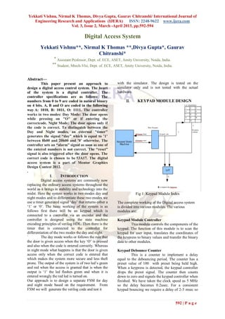
numbers from 0 to 9 are coded in natural binary KEYPAD MODULE DESIGN
on 4 bits. A, B and O are coded in the following
way A: 1010, B: 1011, O: 1111. The controller
works in two modes: Day Mode: The door opens
while pressing on "O" or if entering the
correctcode. Night Mode: The door opens only if
the code is correct. To distinguish between the
Day and Night modes, an external "timer"
generates the signal “day” which is equal to ’1’
between 8h00 and 20h00 and ’0’ otherwise. The
controller sets an “alarm” signal as soon as one of
the entered numbers is not correct. The “reset”
signal is also triggered after the door opens. The
correct code is chosen to be 53A17. The digital
access system is a part of Mentor Graphics
Design Contest 2012.
.
INTRODUCTION
Digital access systems are commonly now
replacing the ordinary access systems throughout the
world as it brings in stability and technology into the
midst. Here the system works in two modes day and Fig 1: Keypad Module Index
night modes and to differentiate these two modes we
use a timer generated signal „day‟ that returns either a The complete working of the Digital access system
„1‟ or „0‟. The basic working of the system is as is divided into various modules. The various
follows first there will be an keypad which is modules are:
connected to a controller via an encoder and the
controller is designed using the state machine Keypad Module Controller
encoding principles of verilog HDL. Then there is the This module controls the components of the
timer that is connected to the controller for keypad. The function of this module is to scan the
differentiation of the two modes the day and night. keypad for user input, translates the coordinates of
` The day mode works or follows the rule that the keypress to binary values and transfer the binary
the door is given access when the key „O‟ is pressed data to other modules.
and also when the code is entered correctly. Whereas
in night mode what happens is that the door is given Keypad Debounce Counter
access only when the correct code is entered that This is a counter to implement a delay
which makes the system more secure and less theft equal to the debouncing period. The counter has a
prone. The output of the system is of two led‟s green preset value of 100 with preset being held high.
and red when the access is granted that is when the When a keypress is detected, the keypad controller
output is „1‟ the led flashes green and when it is drops the presst signal. The counter then counts
entered wrongly the red led is turned on. down to zero and signals the keypad controller when
Our approach is to design a separate FSM for day finished. We have taken the clock speed as 5 MHz
and night mode based on the requirement. From so the delay becomes 0.2usec. For a consistent
FSM we will generate the verilog code and test it keypad bouncing we require a delay of 2-3 msec so
592 | P a g e
2. Yekkati Vishnu, Nirmal K Thomas, Divya Gupta, Gaurav Chitranshi/ International Journal of
Engineering Research and Applications (IJERA) ISSN: 2248-9622 www.ijera.com
Vol. 3, Issue 2, March -April 2013, pp.592-594
we need a counter with initial counter value of
10000 which is a 14 bit wide counter.
Keypad Row Scanner
This is a 5 bit counter/register that is used
to scan the keypad. It keeps all 1 except 1 zero that
cycles through (01111,10111,11011,11101,11110).
This pattern is used to scan the rows of the keypad.
The '0' enables one row at a time to allow key
presses to be detected by columns. The '1's disable
the other rows. The scanner also has an enable signal
which allows the keypad controller to hold the
scanner value in order to determine the coordinates
of the key press.
Look Up Tables (LUT)
We have used a look up table for keypad
coordinate conversion to binary values. The binary
values are used by the comparison module to
compare with the desired authentic code.
Fig 3: FSM in Day Mode
NIGHT FSM.
V. RESULTS
Fig 4: Output waveform for night mode module
Fig 2: FSM of Night Mode
Fig 5: Output waveform for day mode module
As mentioned the night mode works only when the when “o” is given as input
correct code is pressed and the correct code to be
pressed is “53A17”.
The keypad has 13 keys thus a possible 13 states.
Here the FSM used is a mealy one as it depends both
on the input and present state.
IV. DAY FSM
The FSM is similar to the night mode the
only addition being that when the key „O‟ is pressed
the door opens thus an additional state is required Fig 6: Output waveform for day mode module
and this is also an mealy machine.
From Fig 4 we can say that as soon as the correct
code is entered, that is, 53A17 the output is high
593 | P a g e
3. Yekkati Vishnu, Nirmal K Thomas, Divya Gupta, Gaurav Chitranshi/ International Journal of
Engineering Research and Applications (IJERA) ISSN: 2248-9622 www.ijera.com
Vol. 3, Issue 2, March -April 2013, pp.592-594
means that the door will open. In the day mode, we
can switch on the door directly by pressing the O
button which is shown in Fig 5.
ACKNOWLEDGMENT
The authors like to thank Amity University,
Noida for their support and cooperation. The present
work is a part of the design contest conducted by
Mentor Graphics in 2012.
REFERENCES
Iqbalur Rahman Rokon, Toufiq Rahman, Md.
Murtoza Ali Quader, and Mukit Alam,
“Hardware Implementation of Watchdog
Timer for Application in ATM Machine Using
Verilog and FPGA”, International Conference
on Electronics, Biomedical
Engineering and its Applications
(ICEBEA'2012) Jan. 7-8, 2012 Dubai.
K. H. Yeap, H. Nisar, K. H. Chong, Z. I.
Rizman, C. C. Yang, Y. T. Yong and K. C. Lai
, “Design of a Keyless Coded Home Lock
System Using Verilog Hardware Description
Language”, IJECCT 2012, Vol. 3 (1) 10.
Samir Palnitkar, “VERILOG HDL A Guide to
Digital Design and Synthesis”, second edition
pearson.
Wayne wolf, “FPGA based system design”,
prentice hall, 2005.
M. Morris Mano, “Digital Design” prentice
hall, 2008.
Seetha Ramachandran “Digital Vlsi System
Design : A manual for implementation of
projects on FPAs and ASICs using Verilog”,
springer,2007.
T.R. Padmanabhan, B R Bala Tripura Sundari
“Design using verilog HDL”, Institue of
Electronic and electricl engineers,2004
www.ece.ualberta.ca/~elliott/ee552/projects/19
97f/digital_humidifier/vhdl/keypad.vhd
594 | P a g e