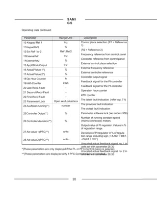
This document is the user manual for SAMI GS frequency converters ranging from 2.2 to 75 kW. It provides instructions for installation, start-up, operation, fault tracing and service. Safety is the top priority, so instructions are given to only allow competent electricians to perform the electrical installation. The manual describes the components and functions of the frequency converter, including the control panel, parameter settings, and fault diagnostics. Tables are included specifying technical details like voltage ratings, current ratings and motor power for each converter type.

![SAMI GS
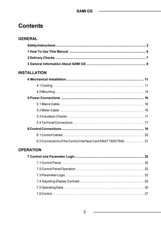
4 Mechanical Installation
SAMI GS is mounted on a wall in a vertical If the cooling ability is reduced too much, the
position using four fixing notches at the top thermal protection operates causing a fault
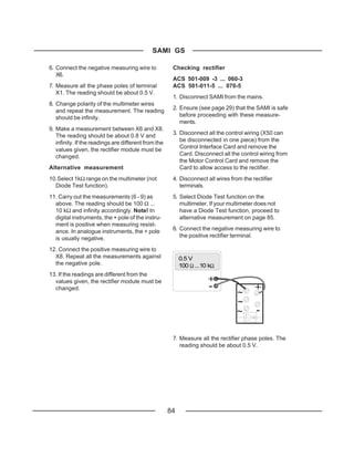
and bottom of the unit. When choosing the indication and stopping the frequency con-
mounting location pay attention to the cool- verter. SAMI GS can be started again when
ing needs of the SAMI GS. the temperature of the cooling element has
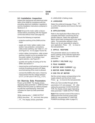
fallen below the tripping level*) (+70 oC).
The temperature of the cooling element can
4.1 Cooling be read from the control panel display
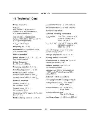
SAMI GS frequency converters are provided (Oper- ating Data, parameter 8, SAMI
with a cooling fan(s) on the bottom of the unit. TEMPERATURE).
The ambient operating temperature for for types ACS 501-050-3, 060-3, 060-5 and
*)
constant torque drives, when the load current 070-5, the tripping level is +75 oC.
is (IN) and switching frequency fS = 3
kHz, is 0 ... 45 oC, except for ACS 501-006-3
and 009-5 0 ... 40 oC. See fig. 4-2 output
current derating curves. The
ambient operating temperature for squared
torque drives, when the load current is (INSQ)
and switching frequency fS = 3 kHz, is 0 ... 40
o
C, except for ACS 501-006-3 and 009-5 0 ...
35 oC. See fig. 4-2 output current derating
curves.
The cooling air must be clean and free from
corrosive materials. Where necessary the
cooling air should be filtered.
If the cooling air contains dust, clean the
cooling surfaces of the unit regularly using
compressed air and a brush.
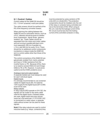
Table 4-1. Required cooling air.
Type ACS 501- [m3/h]
004-3...006-3, 005-5...009-5 51
009-3, 011-3, 011-5, 016-5 102
016-3, 020-3, 020-5, 025-5 406
025-3...060-3, 030-5...070-5 560
11](https://image.slidesharecdn.com/samigsacs501-121206141951-phpapp02/85/ABB-Sami-GS-501-Manual-13-320.jpg)
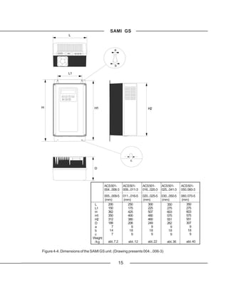
![SAMI GS
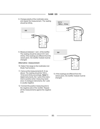
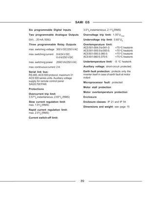
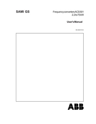
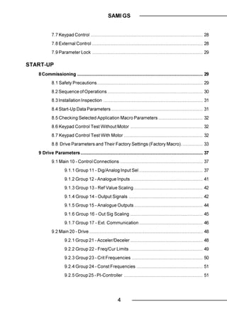
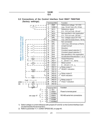
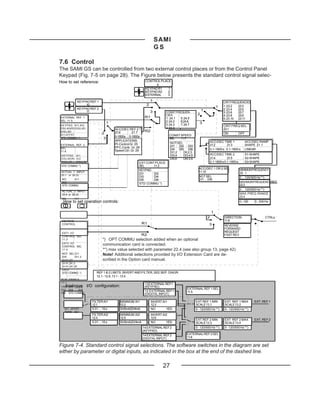
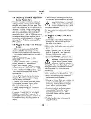
Figure 4-1. Power dissipation as a function of
the switching frequency for different ACS 501
types. Output power in the following curves is
P NSQ.
P l o s s 600 -011-3
[W] -016-5
500
-009-3
400 -011-5
300 -006-3
-009-5
200
-005-3
100 -006-5
-004-3
-005-5
3 4 5 6 7 8 9 10 11 12
f [kHz]
P l o s s 2750 -060-3
-070-5
[W] 2500 -050-3
-060-5
2000 -041-3
-050-5
1500 -030-3
-041-5
1000 -025-3
-030-5
500 -020-3
-025-5
16-70HAV.DRW
-016-3
3 4 5 6 7 8 9 10 11 12 -020-5
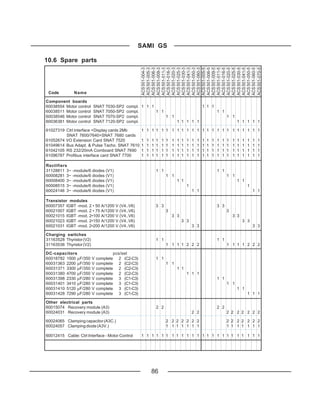
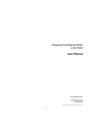
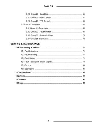
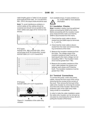
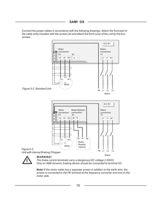
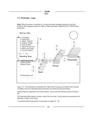
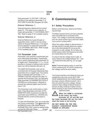
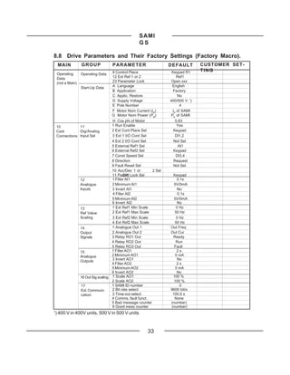
Figure 4-2. Output current derating curves as f [kHz]
a function of ambient temperature and
switching frequency. II out
out
ACS 501
[A]
[A]
-006-3 I NSQ
-009-5 I NSQ 15
-005-3 I NSQ 12 kHz
-006-5 I NSQ
-006-3 IN
10
-009-5 IN 3 kHz
-004-3 I NSQ
-005-5 I NSQ
-005-3 IN 5
-006-5 IN
-004-3 IN
-005-5 IN
10 20 30 40 T
50 a m b Tamb
[°C]C ]
[o
12](https://image.slidesharecdn.com/samigsacs501-121206141951-phpapp02/85/ABB-Sami-GS-501-Manual-14-320.jpg)
![SAMI GS
I out
out
[A]
30
ACS 501
-011-3 12 kHz
I NSQ 3 kHz
-016-5
I NSQ 20
-009-3
I NSQ
-011-5 10
I NSQ
-011-3 IN
-016-5 IN
-009-3 IN
-011-5 IN I out 10 20 30 40 50 T amb
[A] [ oC]
40
3 kHz
ACS 501 12 kHz
-020-3
I NSQ
-025-5
30
I NSQ
-016-3
I NSQ
-020-5
20
I NSQ
-020-3 IN
-025-5 IN
-016-3 IN
10 20 30 40 50 T amb
-020-5 IN
[ o C]
ACS 501
-060-3 I out [A]
I NSQ 120
-070-5 3 kHz-
I NSQ 12 kHz
-050-3 100
I NSQ
-060-3 IN
-060-5 80
I NSQ 3 kHz
-070-5 IN 12 kHz
-050-3 IN
60
-041-3
I NSQ
-060-5 IN
-050-5
40
I NSQ
-030-3 25-70LOA.DRW
I NSQ
-041-3 IN 10 20 30 40 50 T amb
-041-5 [ oC]
I NSQ
-050-5 IN
-025-3 13
I NSQ
-030-5
I NSQ](https://image.slidesharecdn.com/samigsacs501-121206141951-phpapp02/85/ABB-Sami-GS-501-Manual-15-320.jpg)
![SAMI GS
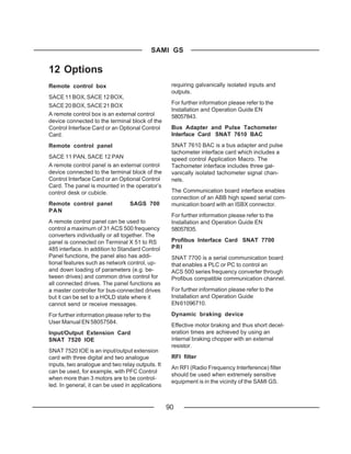
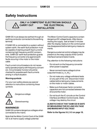
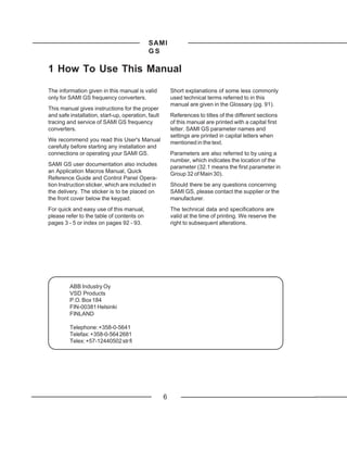
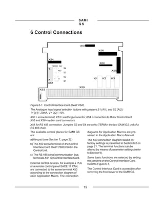
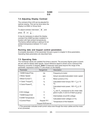
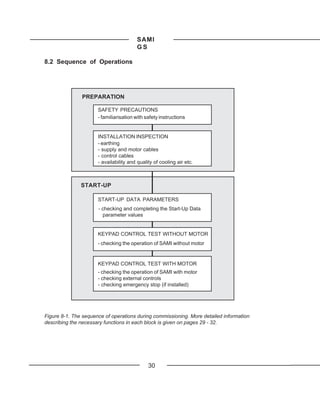
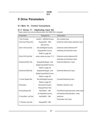
4.2 Mounting
Note! Do not handle or lift the drive using the
Cooling air outlet front cover. Use the bottom part for handling.
d (see table
below) To ensure safe installation, check that the
surface mounting is flat. Mark the fixing points
SAMI GS of SAMI GS on the wall using the template
printed on the protective cardboard package
as a guide. The maximum size of the fixing
screws is 6 mm (15/64") for ACS 501-004-
3...006-3 and ACS 501-005-5...009-5 units and
8 mm (5/16") for 009-3...060-3 and 016-5...070-
5 units.
50 mm 50 mm
Fix the screws to the marked positions.
Attach the unit by the fixing notches and
tighten the screws.
Note! If multiple units are installed adjacent
or above each other, the following minimum
Cooling air distances apply:
50 mm - units side by side, clearance 100 mm - units
inlet
above each other, clearance 300 mm
Type d/[mm]
ACS 501-004...011-3 150
ACS 501-005...016-5 150
ACS 501-016...060-3 250
ACS 501-020...070-5 250
Figure 4-3. Space requirement for adequate
cooling.
14](https://image.slidesharecdn.com/samigsacs501-121206141951-phpapp02/85/ABB-Sami-GS-501-Manual-16-320.jpg)
![SAMI GS
5 Power Connections
5.1 Mains Cable occurring in variable frequency motor drive
SAMI GS is rated for a 380 V/400 V/415 V or systems.
440 V/460 V/480 V/500 V 3-phase system.
To avoid disturbances
A 4-conductor screened cable (three phase
with Protective Earth) is recommended for the Install the motor cable away from other cable
mains cabling. The cables and fuses are to routes. Avoid long parallel runs with other ca-
be dimensioned in accordance with the out- bles (see page 20).
put current. See Table 5-1 for minimum di-
mensions. When dimensioning cables, al- Disturbances caused by radiation from the
ways pay attention to local authority regula- motor cable can be reduced by mounting
tions. Note! Remove all the compen- chokes in the motor cable. These chokes
sation capacitors from the line side so that may reduce the motor voltage and the maxi-
The rapid voltage changes cause capaci-
they are not powered up at the same time as
tive current through the motor cable stray ca-
the SAMI GS.
pacitances. This current rises as the switch-
ing frequency and cable length increase.
5.2 Motor Cable This phenomenon can cause substantially
A 4-conductor screened cable is recom- higher current measured by the SAMI GS
mended due to the rapid voltage changes than the actual motor current, and can cause
overcurrent tripping. This means that when
Table 5-1. Mains & motor cables and fuse recommendations according to output current (IN, INSQ).
Type IN Fuse Cu-cable I NSQ Fuse Cu-cable Max. Cable (Cu or Al)
ACS 501- (A) (A) (mm2) (A) (A) (mm2) (mm2)
004-3/005-5 6.2 10 3*1.5+1.5 7.5 10 3*1.5+1.5 3*2.5+2.5
005-3/006-5 7.5 10 3*1.5+1.5 10.0 10 3*1.5+1.5 3*2.5+2.5
006-3/009-5 10.0 10 3*1.5+1.5 13.2 16 3*2.5+2.5 3*2.5+2.5
009-3/011-5 13.2 16 3*2.5+2.5 18.0 25 3*6.0+6.0 3*6.0+6.0
011-3/(016-5) 18.0 25 3*6.0+6.0 24.0 (26.0) 25 3*6.0+6.0 3*6.0+6.0
016-3/020-5 24.0 25 3*6.0+6.0 31.0 35 3*10+10 3*10+10
020-3/025-5 31.0 35 3*10+10 39.0 50 3*16+16 3*16+16
025-3/030-5 39.0 50 3*16+16 47.0 50 3*16+16 3*35+16
030-3/(041-5) 47.0 50 3*16+16 62.0 (58.0) 63 3*25+16 3*35+16
041-3/(050-5) 62.0 (58.0) 63 3*25+16 76.0 (65.0) 80 3*35+16 3*35+16
050-3/(060-5) 76.0 (65.0) 80 3*35+16 89.0 (84.0) 100 3*50+25 3*70+35
060-3/(070-5) 89.0 (84.0) 100 3*50+25 112 125 3*70+35 3*70+35
Table 5-2. Maximum recomm. length of the motor cable in accord. with switching frequency.
Switching 004...011-3/005...016-5 016-3...020-3/020...025-5 025-3...060-3/030-5...070-5
frequency Screened Unscreened Screened Unscreened Screened Unscreened
[kHz] cable [m] cable [m] cable [m] cable [m] cable [m] cable [m]
1 75 100 100 150 200 250
12 50 75 75 100 150 200
16](https://image.slidesharecdn.com/samigsacs501-121206141951-phpapp02/85/ABB-Sami-GS-501-Manual-18-320.jpg)
![SAMI
GS
7 Control and
Parameter Logic
7.1 Control Panel
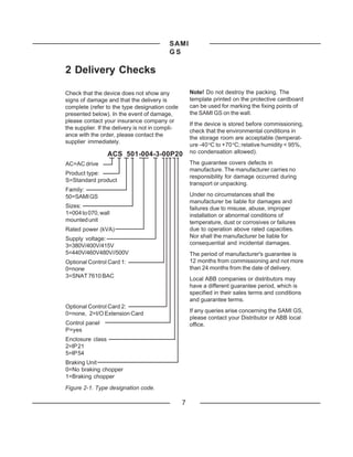
Main name Rotation direction The control panel, situated on top of the
--> forward Control Interface Card, incorporates a 2 by
<-- reverse 20 character, alphanumeric LCD and a
keypad.
DRIVE The operational information, parameters, as
well as fault indications are displayed in nine
20 MAIN R1[ --> languages*): English, Finnish, Swedish, Ger-
I] man, Dutch, French, Danish, Spanish and
Italian. The language selection is made in
Start-Up Data Group parameter A LAN-
Main number Control place Run status GUAGE (refer to page 31).
[ ] Keypad I = Run *) Factory setting is English.
External 0 = Stop
7.2 Control Panel Operation
Panel keys
Selects the Setting mode and saves
the selected parameter value.
Parameter number Active reference
and name R1=Ref 1 R2=Ref 2 Selects Operating Data as well as
Main, Group and Parameter levels. In
Setting mode, returns to the Display
2 ACCELER TIME 1 mode without changing the Param-
[ 30 s ] R1[ --> I] eter value.
In Display mode selects the next/
previous Main, Group or Parameter.
Parameter value Mode indication In Setting mode increases/de-
[ ] Setting mode creases parameter value.
Display mode
Changes the rotation direction in
Keypad control (refer to parameter
Figure 7-1. Control panel displays. Note that 11.8 on page 40).
all the indications may not be visible at the
same time. Starts and stops the motor in Keypad
control. Resets faults, warnings and
supervision indications.
Note! To accelerate the rate of change of
parameter value, keep the or
button depressed continuously.
22](https://image.slidesharecdn.com/samigsacs501-121206141951-phpapp02/85/ABB-Sami-GS-501-Manual-24-320.jpg)
![SAMI
GS
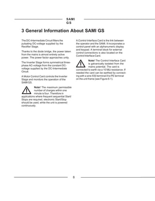
Figure 7-3. Example of control panel operation:
Let us suppose that you want to set the parameter 22.1 MINIMUM FREQUENCY to 3Hz. The
following example explains the procedure.
1 SAMI OUTPUT FREQ
45.5 Hz R1[ --> I ]
Press to Main level
CONT CONNECTIONS
10 MAIN R1[ --> I ]
or Select the required Main level
DRIVE
20 MAIN R1[ --> I ]
Press to Group level
ACCELER/DECELER
21 GROUP R1[ --> I ]
or Select the required Group
FREQ/CUR LIMITS
22 GROUP R1[ --> I ]
Press to Parameter level
1 MINIMUM FREQUENCY Select the required Parameter
5 . 00 Hz R1[ --> I ] by and keys
Change to Setting mode
Brackets indicate that the
1 MINIMUM FREQUENCY
parameter value can now be
[ 5 . 00 Hz ] R1[ --> I ]
changed
Set the parameter value
1 MINIMUM FREQUENCY To cancel the change and return
[ 3 . 00 Hz ] R1[ --> I ] to Display mode, press
Save the selected value to
permanent memory
1 MINIMUM FREQUENCY Brackets disappear indicating
3 . 00 Hz R1[ --> I ] that the parameter value is
stored in memory
Return to Operating Data
1 SAMI OUTPUT FREQ parameter 1 SAMI OUTPUT
45.5 Hz R1[ --> I ] FREQ
24](https://image.slidesharecdn.com/samigsacs501-121206141951-phpapp02/85/ABB-Sami-GS-501-Manual-26-320.jpg)
![SAMI
GS
tions. the frequency reference, select parameter 10
KEYPAD REF1, press the key and
Select Operating Data parameter use the and keys to increase
9, CONTROL PLACE, KEYPAD R1/ or decrease the keypad reference.
KEYPAD R2 for keypad control (Control
place is Ref 1 or Ref 2 accordingly) or When in keypad control using reference 1,
EXTERNAL for external control. The valid it is possible to change the keypad refer-
control place is indicated on the display. ence value while monitoring any of the
[ ] around the direction and run indicators measured values 1-8. For example, you can
means keypad control and without [ ] means monitor parameter 7, SAMI OUTPUT VOLT
while changing the frequency. To do this,
select the measured value you prefer, press
Keypad control key and set the reference frequency
(R1 or R2) with and keys.
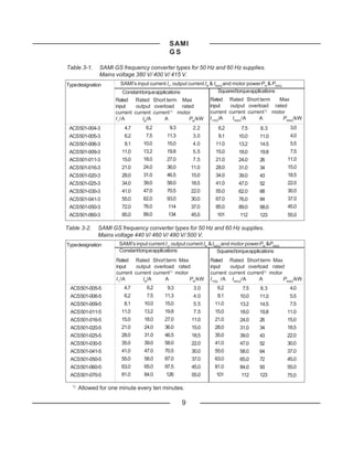
External control If the SAMI GS is running with an external
(manual) reference and the CONTROL PLACE is
10987654321
External control 10987654321
10987654321
10987654321
for example a PLC changed to KEYPAD R1, it is possible to
(automatic) transfer the current value of the external
reference to KEYPAD REF1.
R1 Example: The SAMI GS is receiving a fre-
quency reference from a transducer via X50.
You want to temporarily override the external
R2
frequency reference. Select CONTROL
PLACE, KEYPAD R1 and press and
external control. In addition R1 means Ref 1
. The SAMI GS puts the value of the
and R2 Ref 2 (Figure 7-1).
external reference into KEYPAD REF1. You
Figure 7-5. Control places. may now control the drive manually by
KEYPAD REF1.
7.7 Keypad Control If you enter Display mode by pressing
after selecting CONTROL PLACE, KEYPAD
When Keypad R1 or Keypad R2 is selected R1, the value of parameter KEYPAD REF1
from Operating Data parameter 9, SAMI GS will be the set MINIMUM FREQUENCY.
will operate according to the commands Keypad Reference 2
which are given via the Keypad.
Keypad Reference 2 goes through an
= START/STOP button application block, where it can be manip-
= FORWARD/REVERSE ulated. Keypad Reference 2 can be used as
button a controller reference and it can be given its
Reference own acceleration/deceleration ramps (Refer
signal = see parts Keypad Reference 1 to parameters 21.6 and 21.7 on page 49).
and Keypad Reference 2
Keypad Reference 1 7.8 External Control
The external control place (Ref1/Ref2) is
Operating Data parameter 10 KEYPAD selected with digital input 1-6 or Operating
REF1 is a direct frequency reference. To set
28](https://image.slidesharecdn.com/samigsacs501-121206141951-phpapp02/85/ABB-Sami-GS-501-Manual-30-320.jpg)
![SAMI
GS
MAIN GROUP PARAMETER DEFAULT CUSTOMER SETTING
20 21 1 Acc/Dec Ramp Shape Linear
Drive Acceler/Deceler 2 Acceler Time 1 3s
3 Deceler Time 1 3s
4 Acceler Time 2 60 s
5 Deceler Time 2 60 s
6 Acceler Ref2 Time 60 s
7 Deceler Ref2 Time 60 s
22 1 Minimum Frequency 0 Hz
Freq/Cur Limits 2 Maximum Frequency 50 Hz
3 Output Current 1.5*IN [A]
4 Maximum Freq. range 120 Hz
23 1 Crit Freq Select Off
Crit Frequencies 2 Crit Freq1 Low 0 Hz
3 Crit Freq1 High 0 Hz
4 Crit Freq2 Low 0 Hz
5 Crit Freq2 High 0 Hz
6 Crit Freq3 Low 0 Hz
7 Crit Freq3 High 0 Hz
8 Crit Freq4 Low 0 Hz
9 Crit Freq4 High 0 Hz
10 Crit Freq5 Low 0 Hz
11 Crit Freq5 High 0 Hz
24 1 Const Frequency 1 5 Hz
Const 2 Const Frequency 2 10 Hz
Frequencies 3 Const Frequency 3 15 Hz
4 Const Frequency 4 20 Hz
5 Const Frequency 5 25 Hz
6 Const Frequency 6 40 Hz
7 Const Frequency 7 50 Hz
25 1 PI-Cont Gain 100 %
PI-Controller 2 PI-Cont I-Time 60 s
(Parameters 3 PI-Cont Min Lim 25 Hz
available only if 4 PI-Cont Max Lim 50 Hz
PI- Control 5 Error Value Inv No
macro has been 6 Actual Value Sel Act1
selected) 7 Actual 1 Input No
8 Actual 2 Input No
9 Actual1 Min Scale 0
10 Actual1 Max Scale 0
11 Actual2 Min Scale 0
12 Actual2 Max Scale 0
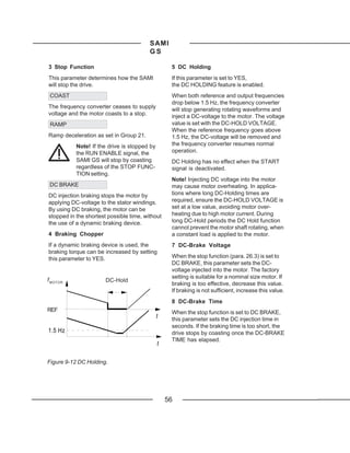
26 1 Start Function Ramp
Start/Stop 2 Torque Boost Cur 1.5*IN [A]
3 Stop Function Coast
4 Brake Chopper No
5 DC-Holding Off
6 DC-Hold Voltage 0.01*UN [V]
7 DC-Brake Voltage 0.01*UN [V]
8 DC-Brake Time 0s
34](https://image.slidesharecdn.com/samigsacs501-121206141951-phpapp02/85/ABB-Sami-GS-501-Manual-36-320.jpg)
![SAMI
GS
MAIN GROUP PARAMETER DEFAULT CUSTOMER SETTING
20 1 Switching Freq 3 kHz
27
Drive 2 SAMI Max Out Volt 100%*UN [V]
Motor Control
3 Motor Power Rated
4 U/f Ratio Linear
5 Field Weak Point 50 Hz
6 IR-Compensation No
7 IR-Comp Voltage 0.01*UN [V]
8 IR-Comp Range 0 Hz
9 Slip Compensation Off
10 Nominal Slip 4%
11 O/U Volt Control On
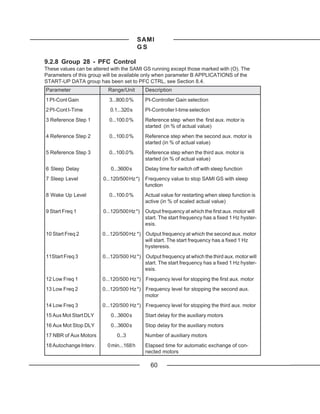
28 1 PI-cont gain 250.0 %
PFC-Control 2 PI-cont I-time 3s
(Parameters 3 Reference step 1 0%
available only if 4 Reference step 2 0%
PFC-control 5 Reference step 3 0%
macro has been 6 Sleep delay 60 s
selected) 7 Sleep level 24 Hz
8 Wake-up level 35.0 %
9 Start freq 1 51.0 Hz
10 Start freq 2 51.0 Hz
11 Start freq 3 51.0 Hz
12 Low freq 1 25 Hz
13 Low freq 2 5 Hz
14 Low freq 3 25 Hz
15 Aux mot start DLY 5s
16 Aux mot stop DLY 3s
17 NBR of aux motos 1
18 Autochang interv. 72 h
19 Autochange level 45.0 %
20 Interlocks ON
21 Error value inv NO
22 Actual 1 input AI 2
23 Actual 2 input NO
24 Actual value sel ACT1
25 ACT1 min scale 100 %
26 ACT1 max scale 100 %
27 ACT2 min scale 100 %
28 ACT2 max scale 100 %
29 Regul Bypass CTRL NO
30 Display Unit bar
31 Display Unit Scale 1000
32 NBR of Decimals 2
35](https://image.slidesharecdn.com/samigsacs501-121206141951-phpapp02/85/ABB-Sami-GS-501-Manual-37-320.jpg)
![SAMI
GS
MAIN GROUP PARAMETER DEFAULT CUSTOMER SETTING
1 Output Freq1 Func No
30 31
2 Output Freq1 Lim 0
Protection Supervision
3 Output Freq2 Func No
4 Output Freq2 Lim 0
5 Current Func No
6 Current Lim 0*IN [A]
7 Ref1 Func No
8 Ref1 Lim 0 Hz
9 Ref2 Func No
10 Ref2 Lim 0%
11 Supervis messages Off
32 1 Serial Fault Func Stop
Fault Function 2 AI <2V/4mA Func No
3 Mot Temp Flt Func Warning
4 Motor Therm Time see Table 9-1
5 Motor Load Curve 150 %
6 External Fan No
7 Stall Func Warning
8 Stall Current 1.2*IN [A]
9 Stall Time/Freq 20 s/25 Hz
10 Underload Func No
11 Underload Time 600 s
12 Underload Curve 1
33 1 Number of Trials 2
Automatic 2 Trial Time 30 s
Reset 3 Overvoltage No
4 Undervoltage Yes
5 Overcurrent No
6 AI Signal <2V/4mA No
34 1 Cri Prog Version
Information 2 MC Prog Version
3 Test Date
36](https://image.slidesharecdn.com/samigsacs501-121206141951-phpapp02/85/ABB-Sami-GS-501-Manual-38-320.jpg)
![SAMI
GS
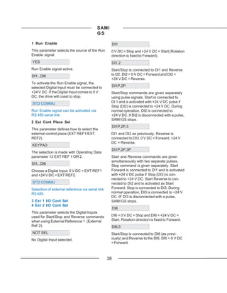
10 Acc/Dec 1 or 2 Sel 11 Param. Lock Sel
This parameter defines which Digital Input This parameter selects the control place for
(1 - 6) is used to select Acceleration/Decel- Parameter Lock.
eration Ramp 1 or 2. If you select KEYPAD, Parameter Lock is
0 V DC = Acc/Dec Time 1 controlled with Operating Data parameter 23,
24 V DC = Acc/Dec Time 2. PARAMETER LOCK. If you select a Digital
Input (1-6), 0 V DC = Open and +24 V DC =
Locked.
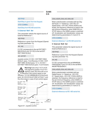
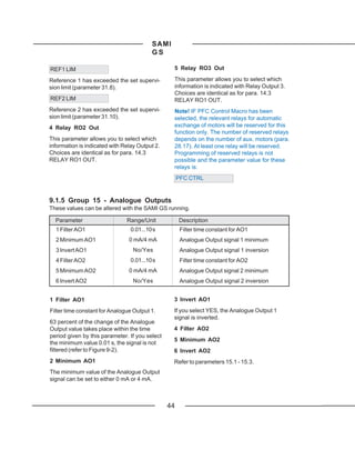
9.1.2 Group 12 - Analogue Inputs
These values can be altered with the SAMI GS running.
Parameter Range/Unit Description
1 Filter AI1 0.01...10 s Filter time constant for AI1
2 Minimum AI1 0 V/0 mA or 2 V/4 mA Analogue Input signal 1 minimum value
3 Invert AI1 No/Yes Analogue Input signal 1 inversion
4 Filter AI2 0.01...10 s Filter time constant for AI2
5 Minimum AI2 0 V/0 mA or 2 V/4 mA Analogue Input signal 2 minimum value
6 Invert AI2 No/Yes Analogue Input signal 2 inversion
1 Filter AI1 2 Minimum AI1
Filter time constant for Analogue Input 1. Analogue input signal can be set to a mini-
63 percent of the change of the Analogue mum of either 0 V/0 mA or 2 V/4 mA. The
Input value takes place within the time period latter value provides a "living zero" function
given by this parameter. If you select the (see page 66, para. 32.2 AI<2 V/4 mA
minimum value 0.01 s, the signal is not FUNC). Refer to page 19 for selection
filtered. between current and voltage input.
3 Invert AI1
[%]
If you select YES, the Analogue Input 1
Unfiltered signal signal is inverted (minimum reference
100 corresponds to maximum output frequency).
This can be used, for example to invert the
63 feedback signal to control a reference in
liquid level control.
Filtered signal
4 Filter AI2
5 Minimum AI2
6 Invert AI2
FILTER AI1
Refer to parameters 12.1 - 12.3.
Figure 9-2. Filter time constant.
41](https://image.slidesharecdn.com/samigsacs501-121206141951-phpapp02/85/ABB-Sami-GS-501-Manual-43-320.jpg)

![SAMI
GS
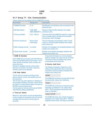
9.1.6 Group 16 - Out Sig Scaling
These values can be altered with the SAMI GS running.
Parameter Range/Unit Description
1 Scale AO1 10...1000 % Analogue Output signal 1 scaling factor
2 Scale AO2 10...1000 % Analogue Output signal 2 scaling factor
1 Scale AO1, 2 Scale AO2 If the desired value should be < 20 mA, the
scaling factor is calculated as follows:
This parameter is the scaling factor for the
Analogue Output 1 (2) signal. If you select a) Minimum output is 0 mA
100 %, the nominal value of the output signal
corresponds to 20 mA. X [%] = 100 % * IAO * Y / (20 mA * Z)
The nominal values for output signal Y are b) Minimum output is 4 mA
as follows:
X [%] = 100 % * (IAO - 4 mA) * Y/(16 mA * Z)
Frequency: 50 Hz
X [%] = scaling value
Speed: motor speed at 50 Hz accord-
I AO = desired output current 0(4) - 20 mA
ing to motor pole number
Y = the nominal value in units of se-
Current: nominal current of motor (IM) lected output signal
Power: nominal power of motor (PM) Z = the desired value in units of output
Torque: nom. power of motor PM/speed signal which corresponds to IAO
(motor data given in Start-Up IAO
Data) [mA]
DC Voltage: DC voltage is 1.35 * nominal
supply voltage (UN, Start up 20
Data par. D). 100 %
Mot. Volt.: UN, Start up Data para. D
Note! If the output voltage is set higher than 200 %
UN (para. 27.2. > 1), the scaling factor should 10 50 %
be < 100 % to reach max voltage with 20 mA.
With PFC macro the nominal values are: 4
Reference value, actual value 1, actual
value 2, PI-Controller output = 100 % of
scaled values. 0 0.5∗Y 1∗Y
Error value: +100 % = 20 mA; -100 % = 0 mA Figure 9-4. Scaling value.
(4 mA). This means that 0 % correspond to
10 mA (12 mA).
If the desired value should be 20 mA, the
scaling factor is calculated as follows:
X [%]= 100 % * Y / Z
45](https://image.slidesharecdn.com/samigsacs501-121206141951-phpapp02/85/ABB-Sami-GS-501-Manual-47-320.jpg)
![SAMI
GS
9.2 Main 20 - Drive
9.2.1 Group 21 - Acceler/Deceler
These values can be altered with the SAMI GS running.
Parameter Range/Unit Description
1 Acc/Dec Ramp Shape Linear/S1...S3 Shape Accel./Decel. ramp shape selection
2 Acceler Time 1 0.1...1800 s Time for fmin - fmax acceleration ramp 1
3 Deceler Time 1 0.1...1800 s Time for fmax - fmin deceleration ramp 1
4 Acceler Time 2 0.1...1800 s Time for fmin - fmax acceleration ramp 2
5 Deceler Time 2 0.1...1800 s Time for fmax - fmin deceleration ramp 2
6 Acceler Ref2 Time 0.1...1800 s Ref2 acceleration ramp time for 0 - 100 %
7 Deceler Ref2 Time 0.1...1800 s Ref2 deceleration ramp time for 100 - 0 %
ffout
out
S1-SHAPE
[Hz]
50 Suitable for ramp times less than one sec-
ond.
Linear S2-SHAPE
S1 Suitable for ramp times less than
1.5 seconds.
S3-SHAPE
S2 Suitable for ramp times up to 15 seconds.
S3 2 Acceler Time 1, 3 Deceler Time 1
4 Acceler Time 2, 5 Deceler Time 2
1 1,25 2t t [s] These times correspond to the time required
Figure 9-5. Acceleration/deceleration ramp for the output frequency to change from
shapes: Linear, S1, S2 and S3. MINIMUM to MAXIMUM FREQUENCY and
vice versa. Regardless of the settings, the
1 Acc/Dec Ramp Shape maximum theoretical acceleration/decelera-
tion is 120Hz/0.1s (max slope = 1200Hz/s)
This parameter allows you to select the
and the minimum 120 Hz/1800s (min slope =
shape of the acceleration/deceleration
0.067 Hz/s). The time required for the accel-
ramp. The available options are (refer to
eration from zero to minimum frequency
Figure 9-5):
depends on the ACCELER TIME (accelera-
LINEAR tion = fmax - fmin/acceleration time).
Suitable for drives requiring steady accel-
eration/deceleration and/or slow ramps.
48](https://image.slidesharecdn.com/samigsacs501-121206141951-phpapp02/85/ABB-Sami-GS-501-Manual-50-320.jpg)
![SAMI
GS
Note! The SAMI GS incorporates a bus The maximum (minimum) recommended
controller that prevents overcurrent and acceleration (deceleration) for the nominal
overvoltage trips caused by too fast size motor is 40 Hz in 1 second. If the motor
acceleration and deceleration for a given rating is less than the nominal power of the
system (by increasing the acceleration/ SAMI GS, smaller settings can be used.
deceleration settings).
If the reference signal changes more slowly
If a small number is entered for the than the acceleration or deceleration time,
acceleration time in a system with high the output frequency change will follow the
inertia, the acceleration time will be limited reference signal. If the reference signal
by the OUTPUT CURRENT (parameter changes faster than the acceleration or
22.3). Conversely, if a small number is deceleration time, the output frequency
entered for deceleration time in such a change will be limited by the parameters.
system, the deceleration time will be limited
6 Acceler Ref2 Time
by the DC link bus regulator. In some cases,
7 Deceler Ref2 Time
the motor will take a long time to come to a
stop. If a short deceleration time is critical to These times correspond to the time required
your application, we suggest you add a for the reference to change from 0 to 100 %
dynamic braking device to your system. and vice versa.
9.2.2 Group 22 - Freq/Cur Limits
These values can be altered with the SAMI GS running.
Parameter Range/Unit Description
1 Minimum Frequency 0...120/500 Hz *) Minimum operating frequency (fmin)
2 Maximum Frequency 0...120/500 Hz *) Maximum operating frequency (fmax)
3 Output Current 0.5...2.0*IN [A ] Output current limit
4 Max. Freq. Range 0 - 120 Hz/0 - 500 Hz*) Normal/Extended Range for ACS 501
*) Max value is set automatically according to the setting of parameter 22.4.
1 Minimum Frequency Note! Current limitation time is not
2 Maximum Frequency supervised. Excessive overcurrent may
cause SAMI to stop the drive due to
The MINIMUM FREQUENCY represents the overtemperature.
minimum output frequency available. In a
similar fashion, the MAXIMUM FREQUENCY Note! If a value greater than 1.5 is entered,
is the maximum output frequency available the SAMI will automatically decrease the limit
(see para. 13.1 and 13.2). to 1.5 when the output frequency is higher
than 0.74 ∗ FIELD WEAK POINT.
3 Output Current
4 Max. freq. Range
This setting determines the max.output cur-
rent the SAMI GS will supply to the motor. If This Parameter extends the setting range of
the rated current of the motor is lower than the parameter 22.1/22.2/13.1 to 13.4/23.2 to
rated current of the SAMI GS, the current limit 23.11/24.1 to 24.7/28.7/28.9 to 28.14/31.2/ 31.4
is recommended to be set in accordance and 31.8.
with the motor rating in standard applications.
49](https://image.slidesharecdn.com/samigsacs501-121206141951-phpapp02/85/ABB-Sami-GS-501-Manual-51-320.jpg)
![SAMI
GS
9.2.3 Group 23 - Crit Frequencies
These values can be altered with the SAMI running.
Parameter Range / Unit Description
1 Crit Freq Select Off / On Critical frequency jump over logic
2 Crit Freq 1 Low 0...120/500 Hz *) Critical frequency 1 start
3 Crit Freq 1 High 0...120/500 Hz *) Critical frequency 1 end
4 Crit Freq 2 Low 0...120/500 Hz *) Critical frequency 2 start
5 Crit Freq 2 High 0...120/500 Hz *) Critical frequency 2 end
6 Crit Freq 3 Low 0...120/500 Hz *) Critical frequency 3 start
7 Crit Freq 3 High 0...120/500 Hz *) Critical frequency 3 end
8 Crit Freq 4 Low 0...120/500 Hz *) Critical frequency 4 start
9 Crit Freq 4 High 0...120/500 Hz *) Critical frequency 4 end
10 Crit Freq 5 Low 0...120/500 Hz *) Critical frequency 5 start
11 Crit Freq 5 High 0...120/500 Hz *) Critical frequency 5 end
*) Max value is set automatically according to the setting of parameter 22.4.
In some systems it may be necessary to If, due to e.g. bearing wear, another reson-
avoid some frequencies because of reson- ance occurs at 34 - 36 Hz, the critical fre-
ance problems. With this Group it is possible quency table can be added to as follows:
to set up five different frequency ranges
6 CRIT FREQ 3 LOW 34 Hz
which the frequency converter will skip. It is
7 CRIT FREQ 3 HIGH 36 Hz
not necessary that, for example, 4 CRIT
FREQ 2 LOW be greater than 3 CRIT FREQ Note! Scale the range to 0 Hz for those
1 HIGH, providing the LOW parameter of any Critical frequencies which are not used.
one set is lower than the HIGH parameter of f motor
the same set. Sets may overlap, but the skip [H z]
will be from the lower LOW value to the
52
higher HIGH value.
46
The Critical Frequency settings are activated
with parameter 1 CRIT FREQ SELECT (Yes).
Example: A fan system has severe vibration 23
problems from 18 Hz to 23 Hz and from 46 Hz 18
to 52 Hz. The speed reference is set to
60 Hz. Set the parameters as follows (set the
"HIGH" value first before setting the "LOW"
f 1low f 1high f 2low f 2high f ref
value):
18 23 46 52 [Hz]
2 CRIT FREQ 1 LOW 18 Hz Figure 9-6. Example of Critical Frequencies
3 CRIT FREQ 1 HIGH 23 Hz settings in a fan system with vibration prob-
4 CRIT FREQ 2 LOW 46 Hz lems at the frequency ranges 18 Hz - 23 Hz
5 CRIT FREQ 2 HIGH 52 Hz and 46 Hz - 52 Hz.
50](https://image.slidesharecdn.com/samigsacs501-121206141951-phpapp02/85/ABB-Sami-GS-501-Manual-52-320.jpg)

![SAMI
GS
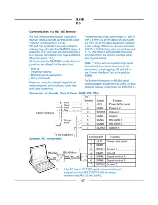
5 Error Value Inv With the minimum and maximum values of
the reference span (Y1min, Y1max) and the
This parameter allows you to invert the Error actual span (X1min, X1max) in units (V, mA) the
Value (and thus the operation of the PI- values are transformed to percentages:
Controller).
Error value
Y1´min = [(Y1min - Y0min) / ∆Y0 ] * 100 %
Y1´max = [(Y1max - Y0min) / ∆Y0 ] * 100 %
X1´min = [(X1min - X0min) / ∆X0 ] * 100 %
PI-Controller
output X1´max = [(X1max - X0min)/ ∆X0 ] * 100%
Gain
Span of the reference value (∆Y1´) and the
t actual value (∆X1´) as a percentage:
PI-CONT I-TIME
Figure 9-9. PI-Controller. ∆Y1´= Y1´max - Y1´min
6 Actual value selection ∆X1´= X1´max - X1´min
This parameter defines how the feedback for Calculation of the maximum actual value
the PI-Controller is calculated. Two analogue (Xs´max) and the minimum actual values as a
values (Act1 and Act2) can be subtracted, percentage (Xs´min) of full reference scale
added or multiplied; also Act1 can be (Y0´=100%, Y0´=0%):
selected on its own. ACT1(2) MAX SCALE:
7 Actual 1 Input, 8 Actual 2 Input Xs´max = X1´max+(100%-Y1´max)*∆X1´/∆Y1´
This parameter selects the input terminal for ACT1(2) MIN SCALE:
Act1 (Act2).
Xs´min = X1´min + (0% - Y1´min) * ∆X1´/ ∆Y1´
9 Act1 min Scale, 10 Act1 max Scale
max
max
11 Act2 min Scale,
X 0 min
X 1 min
X1
X0
12 Act2 max Scale [%] [mA]
2 4 6 8 10 12 14 16 18 20Y0
Y 0 ´ m a x 100
Actual value signals can be scaled to Y 1 ´ max
10 Y 1 m a x
max
correspond to the required regulation range 90 9
∆ X0
80 8
with the minimum and maximum value 70 7
scaling parameters. 60 ∆Y1´ 6
Scaling values can be determined using the 50
∆ Y0
5 [V]
nomogram in figure 9-11 and the formulae as 40 4
Y 1 ´ m i n 30 3 Y1 min
stated below.
20 2
Range of the reference value (∆Y0) and the 10 ∆X1´ 1
actual value (∆X0) in units (V, mA): Y 0 ´ min
Y0 min
10 20 30 40 50 60 70 80 90 100 [%]
∆Y0 = Y0max - Y0min
X S ´ min
X 0 ´ min
X 1 ´ min
X 1 ´ max
X S ´ max
X 0 ´ max
∆X0 = X0max - X0min
Figure 9-10. Basics of scaling factors.
53](https://image.slidesharecdn.com/samigsacs501-121206141951-phpapp02/85/ABB-Sami-GS-501-Manual-55-320.jpg)
![SAMI
GS
Example:
The pressure of a pipe system is to be controlled between 0 and 10 bar.
Pressure transducer for 0 to 10 bar with output span 3 to 9 V, output range 2 to 10 V.
Reference signal is 4 to 20 mA, where 6.4 mA = 0 bar and 16 mA = 10 bar.
Reference value
ACT1(2) MAX SCALE
[mA][V] [mA][V][%]
Xs´max = 118.75
20 10 20 10 100
18 9 18 9 90
16 8 16 8 80 75
14 7 70
14 7
12 6 60
12 6
10 5 50
10 5 8 4 40
8 4 6 3 30
4 2 20 15
6 3
2 1 10
4 2 12.5 87.5 Actual value
Xs´ min = -6.25 10 20 30 40 50 60 70 80 90 100 110 [%]
ACT1(2) MIN SCALE 1 2 3 4 5 6 7 8 9 10 [v]
2 4 6 8 10 12 14 16 18 20 [mA]
2 3 4 5 6 7 8 9 10 [v]
4 6 8 10 12 14 16 18 20 [mA]
Figure 9-11. Scaling of actual value.
∆Y0 = Y0max - Y0min = 20 - 4 = 16 mA
∆X0 = X0max - X0min = 10 - 2 = 8 V
Y1´min = [(Y1min - Y0min)/∆Y0] * 100 % = [(6.4 - 4)/16] * 100 % = 15 %
Y1´max = [(Y1max - Y0min)/∆Y0] * 100 % = [(16 - 4)/16] * 100 % = 75 %
X1´min = [(X1min - X0min)/∆X0] * 100 % = [(3 - 2)/8] * 100 % = 12.5 %
X1´max = [(X1max - X0min)/∆X0] * 100 % = [(9 - 2)/8] * 100 % = 87.5 %
∆Y1´= Y1´max - Y1´min = 75 - 15 = 60 %
∆X1´= X1´max - X1´min = 87.5 - 12.5 = 75 %
Xs´max = X1´max + (100 % -Y1´max)*∆X1´/∆Y1´ = 87.5 + (100 - 75) * 75/60 = 118.75 %
Xs´min = X1´min + (0 % - Y1´min) * ∆X1´/∆Y1´ = 12.5 + (0 - 15) * 75/60 = -6.25 %
ACT1(2) MAX SCALE = 118.8 %
ACT1(2) MIN SCALE = -6.3 %
The Result has been drawn in Figure 9-11 above.
54](https://image.slidesharecdn.com/samigsacs501-121206141951-phpapp02/85/ABB-Sami-GS-501-Manual-56-320.jpg)
![SAMI
GS
9.2.6 Group 26 - Start/Stop
These values can only be altered when the SAMI GS is stopped except those marked with (I).
Parameter Range/Unit Description
1 Start Function Ramp/Flying/Torq Conditions during motor acceleration
Boost/Flying+TQB
2 Torque Boost Cur 0.5...2.0*IN [A] Torque Boost current level selection
3 Stop Function (I) Coast/Ramp/DC-Brake Conditions during motor deceleration
4 Brake Chopper (I) No/Yes Dynamic Braking Device activation
5 DC Holding Off/On Enable DC Holding
6 DC-Hold Voltage 0.01...0.1 * UN [V] Voltage set for DC Holding
7 DC-Brake Voltage 0.01...0.1 * UN [V] Voltage set for DC injection braking
8 DC-Brake Time 0...250 s Duration of DC injection braking
1 Start Function TORQ BOOST
This parameter determines how the SAMI Automatic start current boost, which may be
will start. necessary in drives with high starting torque.
Allows using start current higher than the limit
RAMP
set with para. 22.3. Automatic torque boost is
Ramp acceleration as set in Group 21. active only from 0 Hz to 20 Hz or until the ref-
erence speed is reached. Torque boost is
FLYING not activated if the output frequency falls be-
Use this setting to start the motor if it is low 20 Hz while running.
already rotating, such as in a fan drive.The See also IR COMPENSATION in Group 27.
drive will start smoothly at the present fre-
quency instead of starting at 0 Hz.
Selecting FLYING ensures the drive will ride
through short interruptions of the mains
supply.
Note! Flying start searches for the running FLYING + TQB
speed by applying a small torque to the load
at the MAXIMUM FREQUENCY and Both Flying Start and Torque Boost
decreasing the output frequency until the functions are active.
load speed is found. If the motor is not 2 Torque Boost Cur
coupled to a load or the load has low inertia,
the shaft speed will follow this search The current level used in Torque boost is set
program. Flying start doesn't work properly if by this parameter. Keep the boost current as
several motors are connected to the low as possible for the application.
SAMI GS.
55](https://image.slidesharecdn.com/samigsacs501-121206141951-phpapp02/85/ABB-Sami-GS-501-Manual-57-320.jpg)
![SAMI
GS
9.2.7 Group 27 - Motor Control
These values can only be altered when the SAMI GS is stopped, except those marked with (I).
Parameter Range/Unit Description
1 Switching Freq 1.0 - 12.0 kHz Modulator frequency
2 SAMI Max Out Volt 0.15...1.05*UN [V] Maximum motor voltage selection
3 Motor Power Rated/<Rated/>Rated INmotor/INSAMI-ratio for Motor Controller
4 U/f Ratio Linear/Squared/ Voltage to frequency relationship in region
Automatic below Field Weakening Point
5 Field Weak Point 30...500 Hz Threshold for nominal voltage
6 IR Compensation No/Manual/Automatic Low speed torque boost function
7 IR-Comp Voltage 0.01...0.15*UN [V] Voltage level in manual IR Compensation
8 IR-Comp Range 0...FWP [Hz] Zero point in manual IR Compensation
9 Slip Compensation (I) Off/On Automatic slip reduction
10 Nominal Slip (I) 0.1...10 % Nominal slip of the motor
11 O/U Volt Control (I) Off/On Over-/Undervoltage Controller
1 Switching Freq or higher (>RATED) than the nominal current
of the SAMI.
Motor noise can be minimised by adjusting
the switching frequency to a value that does 4 U/f Ratio
not create resonances in the motor system.
The optimum switching frequency is the LINEAR
lowest frequency at which noise is accept- The voltage of the motor changes linearly
able. This frequency may not be the same with frequency in the constant flux area.
for identical motor systems. Linear U/f ratio is normally used where the
As switching frequency increases, inverter load's torque characteristics is linear with
speed (refer to Figure 9-13).
efficiency goes down (refer to Figure 4-1. on
page 12), so it is best to use a low switching SQUARED
frequency if the application can tolerate
noise. The voltage of the motor is maintained in the
constant flux area less than in the case of
2 SAMI Max Out Volt Linear U/f. The motor is undermagnetised so
This parameter sets the maximum output noise and motor losses are reduced.
voltage (fundamental) of the SAMI. Squared U/f ratio is normally used in ap-
plications where the load torque character-
3 Motor Power istic is proportional to the square of the
speed, such as centrifugal pump and fan
To ensure accurate operation of the Motor drives.
Control Card, it is important to indicate
whether the nominal current of the motor is
the same (RATED +20 %), lower (<RATED)
57](https://image.slidesharecdn.com/samigsacs501-121206141951-phpapp02/85/ABB-Sami-GS-501-Manual-59-320.jpg)
![SAMI
GS
U / U MAX
N AUTOMATIC
[%] Constant flux range
Constant flux range
100 The motor voltage is automatically control-
led to minimise motor losses and noise. This
setting is suitable for a drive which has a
Linear
Linear slowly changing load torque and a motor that
U/f ratio
U/f ratio operates mainly below nominal load.
50
Note! If SQUARED or AUTOMATIC is
selected, then para. 27.6 IR COMPENSA-
TION shoud not be set to AUTOMATIC.
Squared
Squared
10 U/f ratio 5 Field Weak Point
0 Field weakening point f f [Hz]
Field weakening point [Hz] The Field Weakening Point is the frequency
Figure 9-13. The voltage to frequency ratio in at which the output voltage reaches the max-
the frequency range 0 Hz to the field weaken- imum motor voltage (para. 27.2). Above this
ing point can be set to either LINEAR, frequency, the voltage remains at the set
SQUARED or AUTOMATIC. maximum value (UMAX). Also see Figure
9-15.
U Constant flux Field weak. area
6 IR Compensation
U max This parameter allows extra torque at
speeds between 0.1 Hz and the set field
weakening point. The parameter differs from
the TORQ BOOST option of the START
FUNCTION in that it is always valid in the
above mentioned speed range.
50 Hz NO
Field weakening points f[Hz] No compensation wanted.
Figure 9-14. Field weakening point.
MANUAL
UMAX
[V] Constant flux Field weak. area The compensation voltage and range are
380 given by the user (parameters 7 and 8 in this
Group).
AUTOMATIC
240
The IR-Compensation voltage is automat-
ically controlled as a function of effective
motor current. This setting is suitable when
the need for IR Compensation changes and
manual control of the Compensation voltage
is difficult.
50 60 f f [Hz]
Figure 9-15. By adjusting the field weaken- Note! If AUTOMATIC is selected, then
ing point and SAMI MAX OUT VOLT, motors LINEAR should be selected in para. 27.4
other than those of rated voltage can be U/F RATIO.
used.
58](https://image.slidesharecdn.com/samigsacs501-121206141951-phpapp02/85/ABB-Sami-GS-501-Manual-60-320.jpg)
![SAMI
GS
U[V]
U [V] Small motors can take higher compensation
Constant flux Field weak. area than larger motors because the winding
d resistance is higher. If the load torque is high,
use just enough IR-compensation to drive
the load.
8 IR-Comp Range
This parameter defines the frequency at
which the Manual IR COMPENSATION
a reduces to zero. The compensation voltage
reduces linearly with increasing frequency.
b c [Hz]
f [Hz]
Figure 9-16. IR COMPENSATION is imple- 9 Slip Compensation
mented by applying extra voltage to the A squirrel-cage motor will slip under load.
motor. This slip can be compensated by increasing
a=IR-COMP VOLTAGE the frequency as the current increases. By
b=IR-COMP RANGE setting this parameter to ON, slip is reduced
c=FIELD WEAKENING POINT to approximately 10 % of the original value. If
d=SAMI MAX OUT VOLT you require exceptionally precise speed
control, you may want to use a frequency
controller with tachometer feed-back control.
Speed Contact your local SAMI representative for
[rpm] more information.
Compensated speed
1000 10 Nominal Slip
990 For the precise operation of the Slip Com-
pensation function, it is necessary for the
980 SAMI to know the nominal slip of the motor.
Nominal slip is given as a percentage of the
970
Uncompensated speed synchronous speed.
960
Nominal slip of the motor sN [%] can be
derived from synchronous speed ns and
Load
nominal speed nN:
Figure 9-17. Slip compensation reduces slip sN = 100% ∗ (ns - nN)/ns
under load (Example: 6-pole motor).
11 O/U Volt Control
This parameter allows you to turn off the
7 IR-Comp Voltage Over-/Undervoltage Controller. This may be
The compensation voltage level in MANUAL useful for example, if the supply network
IR COMPENSATION. Keep the boost voltage varies more than + 10 % and the
voltage as low as possible for the applica- application will not tolerate the O/U Controller
tion, as the motor will overheat rapidly or an controlling the output frequency in accord-
overcurrent fault may occur when a high level ance with the supply voltage. (An under-/
of compensation is applied. overvoltage trip may occur, instead).
59](https://image.slidesharecdn.com/samigsacs501-121206141951-phpapp02/85/ABB-Sami-GS-501-Manual-61-320.jpg)
![SAMI
GS
Parameter Range/Unit Description
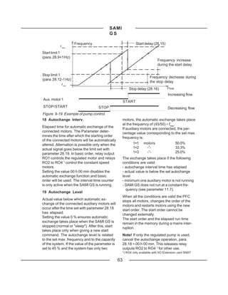
19 Autochange Level(O) 0...100.0 % Actual value level for automatic exchange of
connected aux. motors
20 Interlocks (O) On/Off Enables/disables the interlocking function of aux.
motors
21 Error Value Inv (O) No/Yes Determines whether or not the PI-Controller error
signal is inverted
22 Actual 1 Input (O) No/AI1-AI4/ Actual 1 signal input selection
Std Commu
23 Actual 2 Input (O) No/AI1-AI4 Actual 2 signal input selection
24 Actual Value Sel(O) f(ACT1, ACT2) PFC Controller actual value selection
25 ACT1 Min Scale -1600 %...+1600 % Minimum scaling factor for actual 1 signal
26 ACT1 Max Scale -1600 %...+1600 % Maximum scaling factor for actual 1 signal
27 ACT2 Min Scale -1600 %...+1600 % Minimum scaling factor for actual 2 signal
28 ACT2 Max Scale -1600 %...+1600 % Maximum scaling factor for actual 2 signal
29 Regul Bypass Ctrl No/Yes Bypass selection of the PI-Controller
30 Display Unit No/[Unit] Selection of unit for ACT1 and ACT2
31 Displ Unit Scale 0...50000 Scaling factor for display unit
32 NBR of Decimals 0...5 Number of decimal digits of the displayed actual
values.
*) Max value is automatically set according to the setting of parameter 22.4.
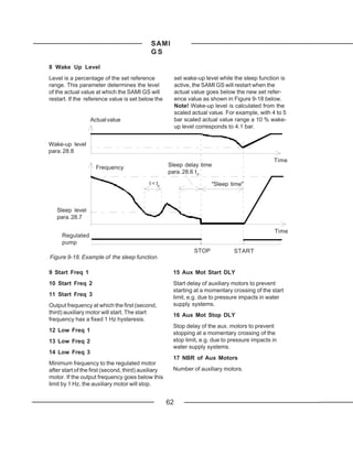
1 PI-Cont Gain, 6 Sleep Delay
2 PI-Cont I-Time
If the output frequency remains below the
See description PI-Control Section 9.2.5 sleep level frequency (parameter 28.7)
longer than the sleep delay set with this
3 Reference Step 1, parameter, the SAMI GS is stopped auto-
4 Reference Step 2,
matically. If the sleep delay is set to 0 s, the
5 Reference Step 3 sleep function is disabled.
Reference value increase after start of the 7 Sleep Level
first (second, third) aux. motor, e.g. in pump
applications with two (or more) pumps, the If the output frequency remains below the
reference value of the regulated pump can frequency set with this parameter longer than
be increased with this parameter to corre- the sleep delay (parameter 28.6) the SAMI
spond to the increased system pressure. GS stops automatically. The PFC Function
supervises actual value changes and re-
starts the SAMI GS when the wake-up level
(para. 28.8) is exceeded.
61](https://image.slidesharecdn.com/samigsacs501-121206141951-phpapp02/85/ABB-Sami-GS-501-Manual-63-320.jpg)
![SAMI
GS
Figure below. l/min, m3/min.
30 Display Unit 31 Displ Unit Scale
Unit of ACT 1 and ACT 2 shown on the Scaling factor for display unit.
display. Units: bar, %, m/s, C (= °C), kPa,
32 NBR of Decimals
Number of decimal digits of the displayed
9.3 Main 30 - Protection actual values.
9.3.1Group 31 - Supervision
These values can be altered with the SAMI GS running.
Parameter Range/Unit Description
1 Output Freq1 Func No/Lowlimit/Highlimit Output Frequency 1 supervision
2 Output Freq1 Lim 0...120/500 Hz*) Output Frequency 1 supervision limit
3 Output Freq2 Func No/Lowlimit/Highlimit Output Frequency 2 supervision
4 Output Freq2 Lim 0...120/500 Hz*) Output Frequency 2 supervision limit
5 Current Func No/Lowlimit/Highlimit Motor Current supervision
6 Current Lim 0...2*IN [A] Motor Current supervision limit
7 Ref1 Func No/Lowlimit/Highlimit Reference 1 supervision
8 Ref1 Lim 0...120/500 Hz*) Reference 1 supervision limit
9 Ref2 Func No/Lowlimit/Highlimit Reference 2 supervision
10 Ref2 Lim 0...100 % Reference 2 supervision limit
11Supervis Messages On/Off Supervision messages on the display
*) Max. value is set automatically according to the setting of parameter 22.4.
5 Current Func
* SAMI SUPERVISION *
Motor Current supervision. Operation as in
2 ACT FREQ 1 R1[ --> I ] parameter 1 OUTPUT FREQ1 FUNC.
Figure 9-21. Example of supervision display. 7 Ref1 Func, 9 Ref2 Func
Reference supervision. Operation as param-
1 Output Freq1 Func eter 1 OUTPUT FREQ1 FUNC.
3 Output Freq2 Func 11 Supervis Messages
These parameters allow you to activate an ON = Supervision messages
Output Frequency supervision function. will be shown on the display.
A Relay Output (para. 14.3 - 14.5) and the dis-
OFF = Supervision messages
play are used to indicate that the Output Fre-
will not be shown on the display. Relays
quency has dropped below (LOWLIMIT) or
operate if programmed for supervision
exceeded (HIGHLIMIT) the supervision limit.
signals.
65](https://image.slidesharecdn.com/samigsacs501-121206141951-phpapp02/85/ABB-Sami-GS-501-Manual-67-320.jpg)
![SAMI
GS
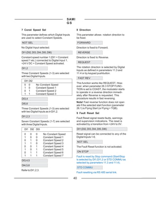
9.3.2 Group 32 - Fault Function
These values can be altered with the SAMI running.
Parameter Range/Unit Description
1 Serial Fault Func Stop/Const Freq Operation following Serial Comm. fault
2 AI < 2 V/4 mA Func No/Warning/Fault/ Operation following AI<2 V/4 mA fault
Const Freq
3 Mot Temp Flt Func No/Warning/Fault Operation following motor overtemp.
4 Motor Therm Time 300...10000 s Time for 63 % motor temperature rise
5 Motor Load Curve 50...150 % Motor current maximum limit
6 External Fan No/Yes Motor equipped with external cooling fan
7 Stall Func No/Warning/Fault Operation following motor stall
8 Stall Current 0...1.5*IN [A] Current limit for Stall Protection logic
9 Stall Time/Freq 10s/15Hz or 20s/25Hz Time/Freq. limit for Stall Protection logic
or 30s/35Hz
10 Underload Func No/Warning/Fault Operation following Underload fault
11 Underload Time 0...600 s Time limit for Underload logic
12 Underload Curve 1...5 Torque limit for Underload logic
1 Serial Fault Func 2 AI < 2V/4mA Func
This parameter allows you to select the This parameter allows you to select the pre-
preferred operation in case of a malfunction ferred operation when the Analogue Input
in the serial communication between the (1 or 2) signal drops below 2V/4mA and the
Control Interface and Motor Control Card. minimum is set to 2V/4mA ("living zero").
STOP NO
The SAMI GS stops according to the setting No activity required.
of parameter 26.3, STOP FUNCTION.
WARNING
CONST FREQ
Warning indication on display.
The SAMI drives the motor at constant
frequency selected with parameter 24.7. FAULT
Note! If the selected control place is Fault indication on display and the drive has
KEYPAD, the SAMI GS stops in case of a stopped according to the setting of param-
serial communication fault. eter 26.3 STOP FUNCTION.
CONST FREQ
The SAMI GS drives the motor with the con-
stant frequency selected by parameter 24.7.
66](https://image.slidesharecdn.com/samigsacs501-121206141951-phpapp02/85/ABB-Sami-GS-501-Manual-68-320.jpg)
![SAMI
GS
3 Mot Temp Flt Func
Motor
load This parameter defines the operation of the
motor thermal protection function.
NO
No activity required.
Temp. tt WARNING
rise
Warning indication is displayed when the
motor temperature reaches the warning level
100 % (95 % of the nominal value).
63 % FAULT
Warning indication at warning level and fault
indication + stop when the motor temperature
tt reaches 100 % level.
MOTOR THERM TIME
4 Motor Therm Time
Figure 9-22. Motor thermal time.
MOTOR THERM TIME is the time period
I/I N Constant flux Field weak. area
I/IN within which the motor temperature reaches
[%] 63 percent of the final temperature rise. As a
150 % rule of thumb, MOTOR THERMAL TIME =
150 120 ∗ t6 (t6 in seconds is given by the motor
100 % manufacturer). SAMI GS automatically
100 selects a typical motor thermal time as a
default value according to the selected
50 %
50 motor power and pole number. Table 9-1,
page 68.
5 Motor Load Curve
6 External Fan
Figure 9-23. Motor load curve
(EXTERNAL FAN = NO). The motor connected to the SAMI GS can be
protected from overheating by the motor
I/I N
I/IN thermal protection. The SAMI GS will calcu-
Constant flux Field weak. area late the temperature rise of the motor using
[%]
150 %
150 the following assumptions:
- the ambient temperature is 40 oC
100 %
100 - the motor is at ambient when power is
applied to the SAMI GS
50 % - when stopped, the motor cooling time is
50
4 times the cooling time when running
Motor heating is calculated assuming a load
curve. The load curve is defined by the
Figure 9-24. Motor load curve MOTOR LOAD CURVE and EXTERNAL
(EXTERNAL FAN = YES). FAN parameters.
67](https://image.slidesharecdn.com/samigsacs501-121206141951-phpapp02/85/ABB-Sami-GS-501-Manual-69-320.jpg)
![SAMI
GS
Table 9-1. Default values of motor thermal If MOTOR LOAD CURVE is set to 100 %, the
times when motor power and pole number Motor Thermal Protection allows the motor to
are selected from START-UP Data group. be loaded with nominal current. The load
These values are typical for each motor curve level should be adjusted if, for ex-
size. Default value of pole number is 4. ample, the ambient temperature differs from
the nominal value.
Number of poles
The motor temperature will rise above nom-
2 4 6 inal when the motor operates in the region
PN t t t above the curve, and will fall when operated
[ kW ] [s] [s] [s] below the curve. The rate of heating and
cooling is set by MOTOR THERM TIME.
2.2 660 1020 1440
Because of the simple thermal model used
3.0 720 1060 1560
for calculating temperature rise, this tech-
4.0 780 1140 1740
nique of thermal protection may cause
5.5 900 1260 1760
undesirable trips when the motor is run
7.5 970 1380 1860
continuously at low frequencies. If your
11 1140 1560 2040
application requires continuous running at
15 1200 1740 2340
frequencies lower than 25 Hz, you may need
18.5 1260 1860 2340
to provide external cooling.
22 1380 2040 2760
30 1680 2220 2940 When using external cooling, set EXTER-
37 1860 2460 3180 NAL FAN to YES. The load curve will be
45 2040 2640 3420 fixed to 70 % current at 0 Hz.
55 2220 2820 3660
75 2400 3120 3960 Note! Motor thermal protection
will not protect the motor if the
cooling efficiency of the motor is
I reduced due to dust and dirt.
7 Stall Func
Stall region This parameter defines the operation (NO/
WARNING/FAULT) of the Stall Protection.
The protection is activated if
Stall current 1) the motor current exceeds the limit set in
parameter 32.8, STALL CURRENT,
2) the output frequency is below the level set
in parameter 32.9, STALL TIME/FREQ
Stall frequency f and
3) The motor current remains above and the
Figure 9-25. Stall Protection.
output frequency below the set level
longer than the period set in parameter
32.9.
68](https://image.slidesharecdn.com/samigsacs501-121206141951-phpapp02/85/ABB-Sami-GS-501-Manual-70-320.jpg)
![SAMI
GS
10 Underload Func
TM A process malfunction can sometimes ap-
Underload Curve pear as a removal of motor load, which is
detected by underload protection. The pro-
tection is activated if
1) the motor torque drops below the load
curve selected in parameter 32.12,
UNDERLOAD CURVE
Underload region 2) the motor torque remains below the load
curve longer than the period set in param-
eter 32.11, UNDERLOAD TIME and
5 Hz f f 3) the output frequency is more than 5 Hz.
Figure 9-26. Underload Protection. The protection function assumes that the
drive is equipped with a nominal size motor.
T/TN
T/TN Select NO/WARNING/FAULT as desired.
[%]
Refer to Figure 9-27, for UNDERLOAD
100 Constant flux Field weak. area CURVE selection.
80 3
60 2
40 1 5
20
4
0
0 20 40 60 80 100 120
f f[Hz]
[Hz]
Figure 9-27. The five available curve types in
parameter 32.12 UNDERLOAD CURVE.
69](https://image.slidesharecdn.com/samigsacs501-121206141951-phpapp02/85/ABB-Sami-GS-501-Manual-71-320.jpg)
![SAMI GS
Note! Undervoltage faults are stored in the
Fault History only when Automatic Reset is
** SAMI WARNING ** off. Supervision limit indications are not
7 A I < 2V/4mA R1[ --> I ] stored in the Fault History but remain on
display until reset by pressing I/O or by
external fault reset. The source of external
fault reset can be selected by parameter
*** SAMI FAULT ** 11.9.
* Note! Factory testing of the SAMI GS in-
8 OVER CURR1 R1[ --> I ] cludes tripping function. However, the Fault
Figure 10-1. Examples of warning and fault History is always erased before shipment,
displays. which means that any faults within the history
have occurred after shipment.
72](https://image.slidesharecdn.com/samigsacs501-121206141951-phpapp02/85/ABB-Sami-GS-501-Manual-74-320.jpg)
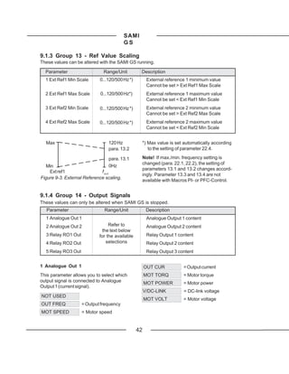
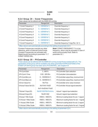
![SAMI GS
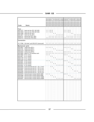
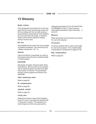
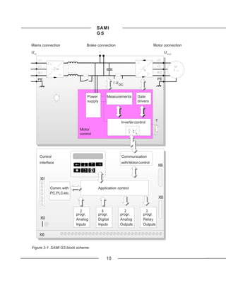
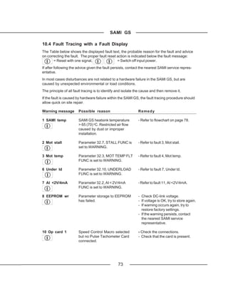
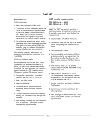
Table 10-1. IGBT module measurements Table 10-3. IGBT module measurements
(Collector - Emitter) ACS 501-004 -3 ... 006 -3, (ACS 501-009 -3 ...060-3, 011-5 ... 070-5).
005-5 ... 009-5. Example: Connect + wire to C1 and - wire to
E1. The reading should be ∞.
Multi- X3 Multi- X2 Reading Multi- Tran- Multi- Tran- Reading
meter meter meter sistor meter sistor
+ U2 − + ≅ 0.4 V + C_ − E_ ∞
+ U2 − − ∞ − C_ + E_ ≅ 0.35 V
+ V2 − + ≅ 0.4 V
+ B_ − C_ ∞
+ V2 − − ∞ + B_ − E_ ∞
+ W2 − + ≅ 0.4 V
+ W2 − − ∞ C1
− U2 + + ∞
− U2 + − ≅ 0.4 V
− V2 + + ∞ B1
E1
− V2 + − ≅ 0.4 V
E1 C2
− W2 + + ∞
− W2 + − ≅ 0.4 V
Example: Connect the + wire to the U2 pole of B2
terminal X3 and the - wire to the + pole of
terminal X2. The reading should be approx. E2 E2
0.4 V. Refer to Figure 10-2 for measuring
points.
Note! If terminal X2 is marked R+ and R- ,
measure + and - from the DC link capacitors Checking rectifier
(see Figure10-2). ACS 501-004-3 ... 006-3
Table 10-2. IGBT module measurements ACS 501-005-5 ... 009-5
(Gate (Base)- Emitter and Gate (Base)-
Collector). 1. Disconnect SAMI from the mains.
ACS 501-004 -3 ... 006 -3, 005-5 ... 009-5.
2. Ensure (see page 29) that the SAMI is safe
Multi- MC Multi- X2 X3 Read. before proceeding with these measure-
meter Card meter [V] ments.
+ G1 − U2 ≅ 1.5 3. Disconnect all the control wiring (X50 can
+ G1 − + ≅ 1.5 be disconnected in one piece) from the
+ G2 − V2 ≅ 1.5 Control Interface Card and remove the
+ G2 − + ≅ 1.5 Card to allow access to the Motor Control
+ G3 − W2 ≅ 1.5 Card.
+ G3 − + ≅ 1.5
4. Disconnect the choke wires from terminals
+ G4 − U2 ≅ 1.2
X6, X7, X8 and X9.
+ G4 − − ≅ 1.2
+ G5 − V2 ≅ 1.2 5. Select Diode Test function from the
+ G5 − − ≅ 1.2 multimeter. If your multimeter does not
+ G6 − W2 ≅ 1.2 have a Diode Test function, proceed to
+ G6 − − ≅ 1.2 "Alternative measurement" on page 84.
83](https://image.slidesharecdn.com/samigsacs501-121206141951-phpapp02/85/ABB-Sami-GS-501-Manual-85-320.jpg)