Download to read offline


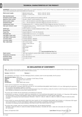
![5.3.6 - Programming diagram This figure also shows the functions and parameters either as they were initially
or following total memory deletion.
EN
The following figure shows the complete programming diagram of the functions
and relative parameters.
Normal
operation P1
Led P1 Slow flashing
ALT Photo Photo Step AUX
1 by P2
step
P3
P1 P1+P2
P1+P2
for 3 secs for 3 secs
for 3 secs
(NO SAVE) (SAVE)
P1 P1
Level one
Led P1 On permanently Autom. Cond. Pre- Close Opening
On P3
Stand Electric Resist. Heavy Proportional
On
closing flashing after delay P2 Off by / Lock STOP. gates Gate P2 Off
Photo Phototest Open
P3 P3
PAUSE TIME
P2 P1
P1
for 3 secs
5 10 20 40 80
P2
seconds
P3
AUXILIARY INPUT (*)
P1
Level two
Led P1 Rapid flashing type 1 type 2 only only Photo 2
p.o p.o opening closing P2
P3
DISCHARGE
P1
0 0,3 0,7 1,3 2
P2
seconds
P3
CURRENT SENSITIVITY
P1
(*)
1 2 3 4 5
P2 a.p. type 1 type 1 partial open, upper leaf
Level moves [N.O.]
P3
a.p. type 2 type 2 partial opening, both
All Leds off · max. current sensitivity motors move for 1/2 the working
time set [N.O.]
OPENING DELAY
Only open open stop open stop…
P1 [N.O.]
5 10 20 30 40 Only closed close stop close stop…
P2
[N.O.]
%
P3 Photo 2 used as photo 2 [N.C.]
8 – English](https://image.slidesharecdn.com/ist280mc424r001-101202162906-phpapp02/85/Ist280-mc424-r001-10-320.jpg)


![5.3.6 - Schema per la programmazione ni ed i parametri pre-impostati inizialmente o dopo una cancellazione completa
Nella seguente figura è riportato lo schema completo della programmazione della memoria.
delle funzioni e dei relativi parametri. Nella stessa figura sono indicate le funzio-
IT
Funzionamento
Normale P1
Led P1 lampeggio lento
ALT Foto Foto Passo AUX
1 Passo P2
P3
P1 P1+P2
P1+P2
per 3 sec per 3 sec
per 3 sec
(non salva) (salva)
P1 P1
Primo Livello
Led P1 acceso fisso Chius. Cond. Prel. Rich. Rit.
On P3
Stantby Elettros. ALT Canc. SCA
On
Auto Dopo Aper. P2 Off Fotot. Res. Pesanti Prop. P2 Off
foto
P3 P3
TEMPO PAUSA
P2 P1
P1
per 3 sec
5 10 20 40 80
P2
secondi
P3
INGRESSO AUSILIARIO (*)
P1
Secondo Livello
Led P1 lampeggio veloce a.p. a.p. solo solo Foto 2
Tipo 1 Tipo 2 apre chiude P2
P3
SCARICAMENTO
P1
0 0,3 0,7 1,3 2
P2
secondi
P3
SENSIBILITÀ AMPEROMETRICA
P1
(*)
1 2 3 4 5
P2 a.p. TIPO 1 Apertura parziale tipo 1,
grado movimento della sola anta
superiore [contatto N.A.]
P3
tutti i Led spenti · amperometrica max a.p. TIPO 2 Apertura parziale tipo 2,
movimento di entrambi i motori
RITARDO IN APERTURA per 1/2 del tempo lavoro
[contatto N.A.]
P1
Solo Open open stop open stop...
5 10 20 30 40 [contatto N.A.]
P2
%
Solo Chiude chiude stop chiude stop...
P3 [contatto N.A.]
Photo 2 Utilizzato come photo 2
[contatto N.C.]
8 – Italiano](https://image.slidesharecdn.com/ist280mc424r001-101202162906-phpapp02/85/Ist280-mc424-r001-22-320.jpg)


![5.3.6 - Schéma pour la programmation les fonctions et les paramètres préprogrammés initialement ou après un efface-
La figure ci-dessous donne le schéma complet de la programmation des fonc- ment complet de la mémoire.
tions et des paramètres correspondants. Dans la même figure sont indiquées
Fonctionnement
normal P1
FR
Led P1 Clignotement lent
HALTE Photo Photo Pas AUX
1 à-pas P2
P3
P1 P1+P2
P1+P2
pendant 3 s pendant 3 s
pendant 3 s
(ne pas sauvegarder) (sauvegarder)
P1 P1
Premier Niveau
Led P1 allumée fixe Autom. Collectif Précl. Referme Décalage
On P3
Stand-by Serrure Stop Portails SCA
On
ap. photo P2 Off Phototest résistif lourds proport. P2 Off
P3 P3
Temps de pause
P2 P1
P1
pendant 3 s
5 10 20 40 80
P2
secondes
P3
Entrée auxiliaire (*)
P1
Deuxième niveau
Led P1 clignotement rapide o.p. o.p. ouvre ferme Photo 2
type 1 type 2 seul. seul. P2
P3
Décharge
P1
0 0,3 0,7 1,3 2
P2
secondes
P3
Sensibilité ampèremétrique
P1
(*)
1 2 3 4 5 o.p. TYPE 1 Ouverture partielle type 1,
P2
degré mouvement uniquement du vantail
supérieur [contact N.O.]
P3
o.p. TYPE 2 Ouverture partielle type 2,
toutes les LED éteintes · force ampèremétrique max.
mouvement des deux moteurs
Décalage en ouverture pour la moitié du temps de travail
[contact N.O.]
P1
Seulement ouverture stop ouvre stop...
5 10 20 30 40 ouverture [contact N.O.]
P2
%
Seulemen fermeture stop ferme stop...
P3
fermeture [contact N.O.]
Photo 2 utilisé comme photo 2
[contact N.F.]
8 – Français](https://image.slidesharecdn.com/ist280mc424r001-101202162906-phpapp02/85/Ist280-mc424-r001-34-320.jpg)


![ABRIR PARCIAL TIPO 2 NA Abre las 2 hojas hasta la mitad de la carrera
ABRIR NA Ejecuta sólo el movimiento de apertura
CERRAR NA Ejecuta sólo el movimiento de cierre
FOTO 2 NC Función FOTO 2
DESACTIVADA -- Ninguna función
2.4.1 - Notas sobre las conexiones Nota 3 – Uno o varios dispositivos NC se pueden conectar en serie entre sí y a
La mayoría de las conexiones son muy sencillas de hacer; una gran parte de una resistencia de 8,2KΩ sin ningún límite de cantidad (fig. 9c).
éstas son conexiones directas a un solo equipo o contacto. En las siguientes Nota 4 – Sólo un dispositivo con salida de resistencia constante 8,2 KΩ puede
figuras se muestran algunos ejemplos para conectar los dispositivos exteriores: conectarse; si fuera necesario, varios dispositivos pueden conectarse “en cas-
cada” con una sola resistencia de terminación de 8,2 KΩ (fig. 9d).
• Conexión Stand By / Fototest
La función Stand-by está activa de serie; se desactiva automáticamente sólo 2.5 - Primer encendido y control de las conexiones eléctricas
cuando se activa la función Fototest. Nota - Las funciones Stand-by y Fototest
son alternativas porque una desactiva la otra. ¡ATENCIÓN! – Las operaciones de conexión deben ser realizadas exclu-
La función Stand-by permite reducir los consumos; es posible obtener tres sivamente por personal cualificado.
ES
tipos de conexiones: Después de haber conectado la alimentación eléctrica de la Central de mando,
- con “stand by” activa (ahorro de energía); véase el esquema eléctrico de la fig. 5a controle que todos los Leds destellen rápidamente durante algunos segundos;
- conexión estándar: sin “stand by” y sin “fototest”; véase el esquema eléctrico posteriormente realice los siguientes controles:
de la fig. 5b 1. Controle que en los bornes 9-10 haya una tensión de alrededor de 30 Vdc;
- sin “stand by” y con “fototest”; véase el esquema eléctrico de la fig. 5c si los valores fueran incorrectos, corte inmediatamente la alimentación y
Con la función “Stand-by” activa, transcurrido un minuto desde el final de un controle detenidamente las conexiones y la tensión de alimentación.
movimiento, la central se colocará en Stand-by, apagando todas las Entradas y 2. Después del destello rápido inicial, el Led P1 señalará el funcionamiento
las Salidas para disminuir los consumos. La condición será señalada por el led correcto de la central con un destello regular cada un segundo. Cuando en
“OK” que comenzará a destellar más lento. ADVERTENCIA – Si la central las entradas se produzca una variación, el LED “P1” realizará dos destellos
estuviera alimentada con un panel fotovoltaico (sistema “Solemyo”) o con una rápidos que significa que la entrada ha sido reconocida.
batería compensadora, habrá que activar la función “Stand-by”, tal como se 3. Si las conexiones son correctas, las entradas “NC” deberán tener el Led
muestra en el esquema eléctrico de fig. 5a. encendido, mientras que las entradas “NA” deberán tener el Led apagado.
Cuando no sirva la función “Stand-by”, se podrá activar la función “Fototest” Véanse la fig. A y la Tabla 2.
que permite comprobar, al comienzo de un movimiento, el funcionamiento
correcto de las fotocélulas conectadas. Para utilizar esta función primero habrá
que conectar oportunamente las fotocélulas (véase el esquema eléctrico de la
fig. 5c) y después activar la función. A
Nota – Activando el fototest, las entradas que intervienen en el procedimiento
de test son FOTO, FOTO1 y FOTO2. Si no se utilizara una de estas entradas,
habrá que conectarla al borne n° 8.
• Conexión Selector de llave
Ejemplo 1 (fig. 7a): Cómo conectar el selector para las funciones PASO A
PASO y ALT
Ejemplo 2 (fig. 7b): Cómo conectar el selector para las funciones PASO A
PASO y una de aquellas previstas para la entrada auxiliar (APERTURA PAR-
CIAL, SÓLO ABRIR, SÓLO CERRAR, etc.)
TABLA 2
Nota – Para las conexiones eléctricas con la función “Stand By” activa, véase
“Función Stand By/Fototest” en este párrafo 2.4.1. ENTRADA TIPO ENTRADA CONDICIÓN LED
• Conexión Indicador Cancela Abierta / Electrocerradura (fig. 8) ALT ALT NC L1 Encendido
Si estuviera programado S.C.A., la salida podrá utilizarse como indicador cance- ALT RESISTENCIA L1 Encendido
la abierta. El indicador destellará lentamente durante la apertura, mientras que CONSTANTE 8,2 KΩ
destellará rápidamente durante el cierre; quedará encendido con luz fija cuando
la cancela esté detenida en posición abierta y quedará apagado cuando la can- FOTO NC L2 Encendido
cela esté cerrada. Si la salida estuviera programada como electrocerradura, se FOTO1 NC L3 Encendido
activará durante 3 segundos cada vez que comience el movimiento de apertura. P.P. NA L4 Apagado
2.4.2 - Tipo de entrada ALT AUX ABRIR PARCIAL tipo 1 - NA L5 Apagado
La central MC424 puede programarse para dos tipos de entrada ALT: ABRIR PARCIAL tipo 2 - NA L5 Apagado
- Alt tipo NC para la conexión a contactos NC.
- Alt de resistencia constante. Permite conectar a la central dispositivos con SÓLO ABRIR - NA L5 Apagado
salida de resistencia constante 8,2 KΩ (ejemplo bandas sensibles). La entra- SÓLO CERRAR - NA L5 Apagado
da mide el valor de la resistencia y desactiva el movimiento cuando la resis- FOTO2 NC L5 Encendido
tencia sale del valor nominal. Mediante oportunas soluciones, también es
posible conectar en la entrada alt de resistencia constante algunos dispositi-
4. Controle que al activar los dispositivos conectados en las entradas se apa-
vos con contactos normalmente abiertos “NA”, normalmente cerrados “NC”
guen o se enciendan los Leds correspondientes.
y varios dispositivos, incluso de diferentes tipos; véase la Tabla 1.
5. Compruebe que al pulsar el botón P2 ambos motores realicen un movi-
¡ATENCIÓN! – Si se utilizara la entrada ALT de resistencia constante para miento breve de apertura, arrancando primero el motor de la hoja superior.
conectar dispositivos con funciones de seguridad, sólo los dispositivos Bloquee el movimiento pulsando de nuevo el botón P2. Si los motores no
con salida de resistencia constante 8,2 KΩ garantizan la categoría de
arrancaran en el sentido de apertura, invierta las polaridades de los cables
seguridad 3 contra las averías.
del motor, mientras que si el primer motor que se mueve no es el de la hoja
superior, cambie el puente de conexión E (fig. 2).
TABLA 1
1° dispositivo tipo:
2.6 - Búsqueda automática de los fines de carrera
2° dispositivo tipo:
Finalizados los controles, se puede comenzar con la etapa de búsqueda auto-
NA NC 8,2 KΩ mática de los topes mecánicos que sirve para que la central MC424 “mida” los
NA En paralelo (nota 1) (nota 2) En paralelo tiempos de duración de los movimientos de apertura y cierre. Este procedi-
miento es completamente automático y se basa sobre la medición del esfuerzo
NC (nota 2) En serie (nota 3) En serie
de los motores para la detección de los topes mecánicos de apertura y cierre.
8,2KΩ En paralelo En serie (nota 4) ¡Atención! – Si ya se hubiera hecho este procedimiento, para reactivarlo,
primero habrá que borrar la memoria (véase el capítulo “Borrado de la
Notas de la Tabla 1: memoria”). Para comprobar si la memoria contiene los parámetros de los
Nota 1 – Uno o varios dispositivos NA se pueden conectar en paralelo entre sí fines de carrera, corte y active nuevamente la alimentación de la central.
sin límites de cantidad con una resistencia de terminación de 8,2 KΩ (fig. 9a). Si todos los Leds destellaran rápidamente durante 6 segundos, significa
Para las conexiones eléctricas con la función “Stand By” activa, véase “Función que la memoria está vacía; si el destello durara sólo 3 segundos, significa
Stand By/Fototest” en este párrafo 2.4.1. que la memoria contiene los parámetros de los fines de carrera.
Nota 2 – La combinación NA y NC es posible colocando los 2 contactos en Antes de comenzar la búsqueda de los fines de carrera, controle que todos los
paralelo entre sí, teniendo cuidado en conectar en serie el contacto NC con dispositivos de seguridad den su autorización (ALT, FOTO y FOTO1 activos). La
una resistencia de 8,2 KΩ [también es posible la combinación de 3 dispositi- activación de un dispositivo de seguridad o la llegada de un mando durante el
vos: NA, NC y 8,2 KΩ (fig. 9b)]. procedimiento provoca la interrupción inmediata. Las hojas pueden estar en
Español – 3](https://image.slidesharecdn.com/ist280mc424r001-101202162906-phpapp02/85/Ist280-mc424-r001-41-320.jpg)


![5.3.6 - Esquema para la programación los parámetros preconfigurados antes o después de borrar completamente la
En la siguiente figura se indica el esquema completo de la programación de las memoria.
funciones y de sus parámetros. En la misma figura se indican las funciones y
Funcionamiento
Normal P1
Led P1 Destello lento
STOP Fotocélula Fotocélula Paso a AUX
1 Paso P2
P3
ES
P1 P1+P2
P1+P2
por 3 seg por 3 seg
por 3 seg
(no memorizar) (memorizar)
P1 P1
Primer Nivel
Led P1 encendido continuo Cierre Comunitario Destello Cerrar Retardo
On P3
Stand by Electrocer. Stop Puertas SCA
On
auto. previo después Apertura P2 Off Fototest resistivo pesadas proporcional P2 Off
de
fotocélula
P3 P3
TIEMPO DE PAUSA
P2 P1
P1
por 3 seg
5 10 20 40 80
P2
segundos
P3
ENTRADA AUXILIAR (*)
P1
Segundo Nivel
Led P1 destello rápido a.p. a.p. sólo sólo Fotocélula
Tipo 1 Tipo 2 abrir cerrar 2 P2
P3
DESCARGA
P1
0 0,3 0,7 1,3 2
P2
segundos
P3
SENSIBILIDAD SISTEMA AMPERIMÉTRICO
P1
(*)
1 2 3 4 5 a.p. TIPO 1 Apertura parcial tipo 1,
P2
grado movimiento de la hoja superior
[contacto N.A.]
P3
a.p. TIPO 2 Apertura parcial tipo 2,
todos los Leds apagados · sistema amperimétrico max
movimiento de ambos motores
RETARDO DURANTE APERTURA durante la mitad del tiempo de
funcionamiento [contacto N.A.]
P1
Sólo Abrir abrir stop abrir stop...
5 10 20 30 40 [contacto N.A.]
P2
%
Sólo Cerrar cerrar stop cerrar stop...
P3 [contacto N.A.]
Foto 2 Utilizado como foto 2
[contacto N.C.]
8 – Español](https://image.slidesharecdn.com/ist280mc424r001-101202162906-phpapp02/85/Ist280-mc424-r001-46-320.jpg)


![5.3.6 - Programmierungsschema auch die ursprünglich eingegebenen Funktionen und Parameter bzw. die Funk-
Auf der folgenden Abbildung ist das komplette Programmierungsschema der tionen und Parameter angegeben, die nach einem vollständigen Löschen des
Funktionen und der jeweiligen Parameter gezeigt. Auf dieser Abbildung sind Speichers eingestellt sind.
Normalbetrieb P1
Led P1 Langsamblinken
Schrittbetrieb
STOP Foto Foto AUX
1 P2
P3
P1 P1+P2
P1+P2
3 Sek.lang 3 Sek.lang
3 Sek.lang
(nicht speichert) (speichert)
DE
P1 P1
Erste Stufe
Phototest
Vorwarnen
Zulauf nach Foto
Schwere Tore
SCA proportional
Wohnblockbetrieb
Stop durch resistiven
Codeschloss
Stand by
Led P1 leuchtet fest
Automatische
Verzögerung P2 On P3 P2 On
Schließung
in Öffnung
Off Off
Widerstand
P3 P3
PAUSEZEIT
P2 P1
P1
3 Sek.lang
5 10 20 40 80
P2
Sekunden
P3
HILFSEINGANG (*)
P1
Zweite Stufe
Nur Schließung
Nur Öffnung
Led P1 Schnellblinken o.p. o.p. Foto 2
Typ 1 Typ 2 P2
P3
ENTLADEN
P1
0 0,3 0,7 1,3 2
P2
Sekunden
P3
ANSPRECHVERMÖGEN STROMMESSUNG
P1
(*)
1 2 3 4 5 T.Ö. Typ 1 Teilöffnung Typ 1,
P2
Stufe
Bewegung des oberen Flügels
[NO-Kontakt]
P3
T.Ö. Typ 2 Teilöffnung Typ 2,
alle Leuchtanzeigen aus · max. Stromaufnahme Bewegung beider Antriebe für
VERZÖGERUNG IN ÖFFNUNG die Hälfte der Arbeitszeit
[NO-Kontakt]
P1
Nur Öffnung öffnet Stopp öffnet Stopp...
[NO-Kontakt]
5 10 20 30 40
P2
% Nur Schließung schließt Stopp schließt Stopp...
P3 [NO-Kontakt.]
Photo 2 als Photo 2 benutzt
[NC-Kontakt]
8 – Deutsch](https://image.slidesharecdn.com/ist280mc424r001-101202162906-phpapp02/85/Ist280-mc424-r001-58-320.jpg)


![5.3.6 - Schemat programowania funkcje i parametry ustawione fabrycznie lub po całkowitym skasowaniu
Na poniższym rysunku przedstawiony jest kompletny schemat programowania pamięci.
funkcji i odnośnych parametrów. Na tym samym rysunku pokazane są również
Normalny stan
pracy P1
Dioda P1 błyska wolno
STOP F oto Foto Krok AUX
1 po P2
kroku
P3
P1 P1+P2 -- Najpierw P1 !
P1+P2
przez 3 s. przez 3 s.
przez 3 s.
(rezygnacja) (zapamietaj)
P1 P1
Poziom 1
Dioda P1 świeci na stałe Autom. z.mieszk. Wstęp. Zamknij Opóźnienie Stand Elektro- Rezyst. Ciężkie P roporcionalne
Wł. P3 Wł.
zamyk. świecenie po otwierania P2 by zamek STO P bramy światełko P2
PL
Wył. Wył.
Foto Fototest
P3 P3
CZAS PAUZY
P2 P1
P1
przez 3 s.
5 10 20 40 80
P2
sekund
P3
WEJŚCIE UNIWERSALNE AUX (*)
P1
Poziom 2
Dioda P1 błyska szybko furtka furtka tylko tylko Foto 2
typ 1 typ 2 otwiera zamyka P2
P3
ODPRĘŻENIE
P1
0 0,3 0,7 1,3 2
P2
sekund
P3
SIŁA NACISKU SKRZYDEŁ
P1 (*)
“furtka” 1 - Otwieranie częściowe 1-go typu,
1 2 3 4 5 go TYPU ruch samego skrzydła wierzchniego
P2 [wejście typu N.A.]
Poziom
P3 “furtka” 2 - Otwieranie częściowe 2-go typu,
go TYPU ruch obu silników
Wszystkie diody zgaszone - największa siła przez połowę czasu pracy
[wejście typu N.A.]
OPÓŹNIENIE DRUGIEGO SKRZYDŁA
Tylko otwieranie stop otwieranie stop...
P1 Otwieranie [wejście typu N.A.]
5 10 20 30 40
P2 Tylko zamykanie stop zamykanie stop...
% Zamknięcie [wejście typu N.A.]
P3
Foto 2 Wykorzystywany jako foto 2
[wejście typu N.C.]
8 – Polski](https://image.slidesharecdn.com/ist280mc424r001-101202162906-phpapp02/85/Ist280-mc424-r001-70-320.jpg)


![5.3.6 - Programmeerschema de functies en parameters aangegeven die aanvankelijk of na volledig wissen
Op onderstaande afbeelding vindt u het complete schema voor programmering van het geheugen vooringesteld (fabrieksinstelling) zijn.
van de functies en de daarbij horende parameters. Op deze afbeelding zijn ook
Normale Werking P1
Led P1 knippert langzaam
STOP Foto Foto Stap AUX
1 voor P2
Stap
P3
P1+P2 P1 P1+P2 - Eerst P1!
gedurende gedurende
gedurende 3 sec. 3 sec.
3 sec. (bewaart niet) (bewaart)
P1 P1
Eerste niveau
Led P1 brandt continu Auto. Woonbl. VrW. Terug Vertr.
On P3
Stand Elektros. STOP Zware SCA
On
Sluiten na foto Open. P2 Off by Wrst. Poorten Prop. P2 Off
Fototest
P3 P3
NL
PAUZEDUUR
P2 P1
gedurende P1
3 sec. 5 10 20 40 80
P2
seconden
P3
HULPINGANG (*)
P1
Tweede niveau
Led P1 knippert snel a.p. a.p. Alleen Alleen Foto 2
Type 1 Type 2 openen sluiten P2
P3
DRUKAFVOER
P1
0 0,3 0,7 1,3 2
P2
seconden
P3
GEVOELIGHEID STROOMMETING
P1 (*)
a.p. TYPE 1 Gedeeltelijke opening type 1,
1 2 3 4 5
P2 alleen manoeuvre van de
graad bovenste vleugel [NO contact]
P3
a.p. TYPE 2 Gedeeltelijke opening type 2,
alle Leds uit. - max. stroommeting manoeuvre van beide motoren
gedurende de 1/2 van de
VERTRAGING IN HET OPENEN bedrijfstijd [NO contact]
P1 Alleen openen open stop open stop...
[NO contact]
5 10 20 30 40
P2
%
Alleen sluiten sluit stop sluit stop...
[NO contact]
P3
Foto 2 Gebruikt als foto 2
[NC contact]
8 – Nederlands](https://image.slidesharecdn.com/ist280mc424r001-101202162906-phpapp02/85/Ist280-mc424-r001-82-320.jpg)


This document provides safety warnings and installation instructions for a Moon Control unit MC424. It warns that incorrect installation could cause injury and to read the manual carefully. It also details important warnings for handling, modifying, using near heat/flames, and disposing of packaging properly. Installation instructions include connecting to an earthed power line, using overvoltage protection, and routing cables through glands to prevent condensation damage.


