Downloaded 13 times


![Rockwell Automation Publication 1766-UM001O-EN-P - September 2021 145
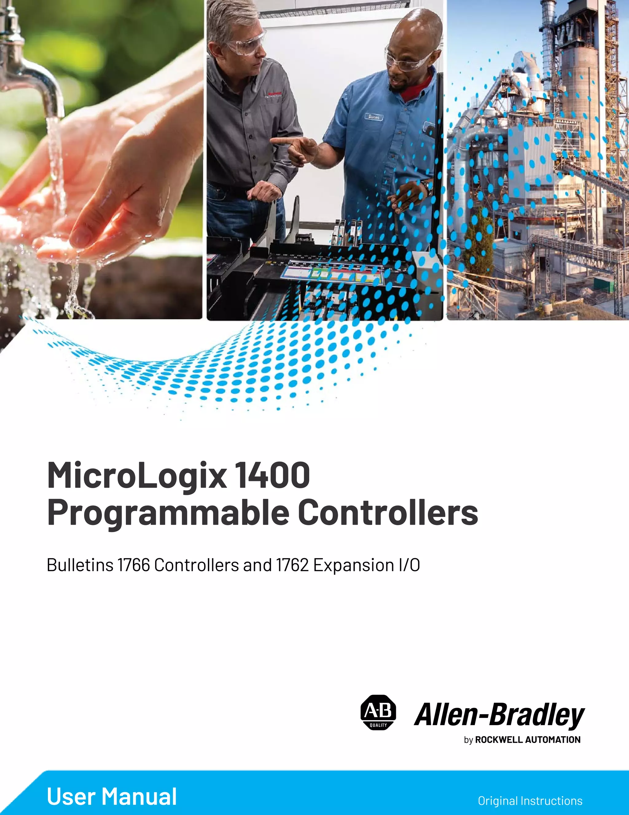
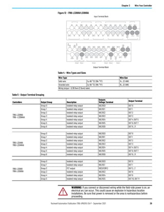
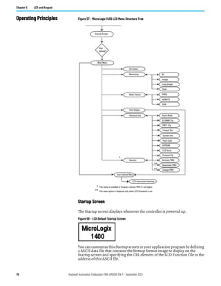
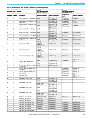
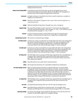
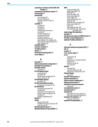
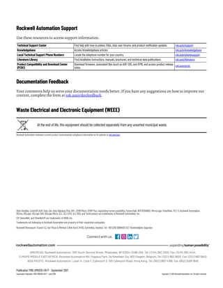
Appendix A Specifications
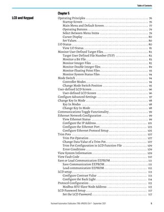
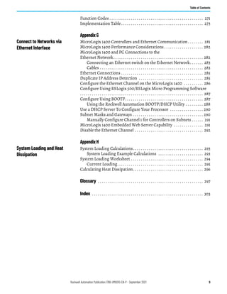
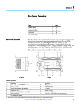
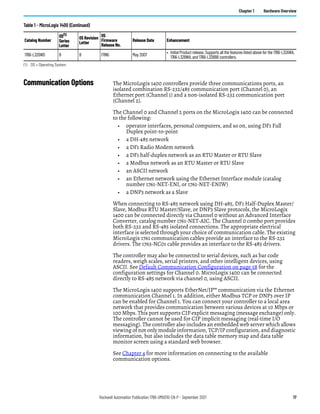
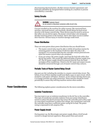
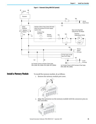
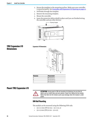
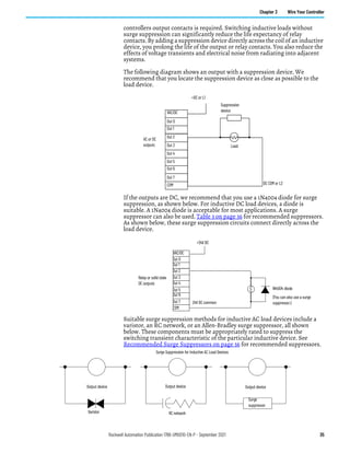
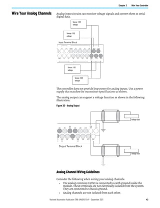
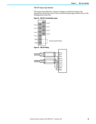
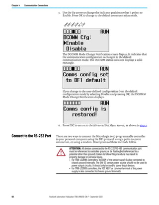
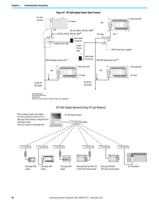
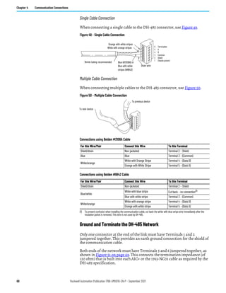
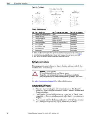
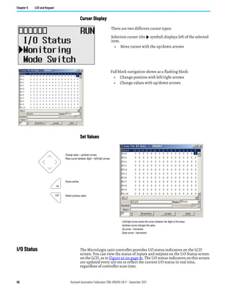
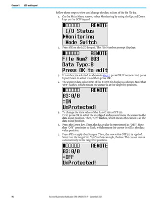
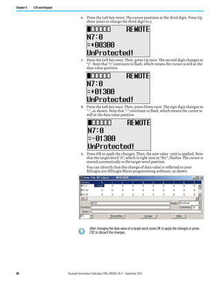
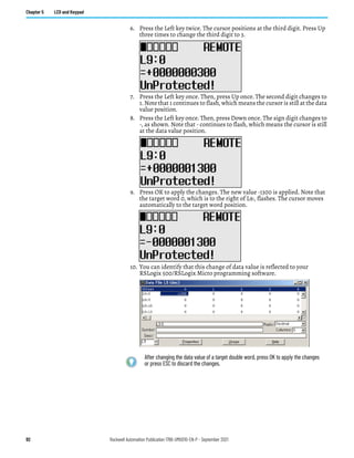
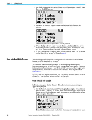
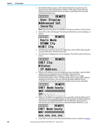
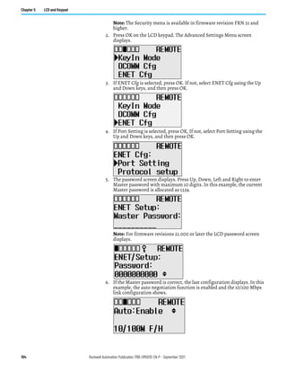
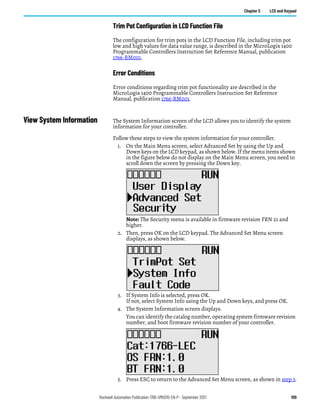
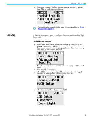
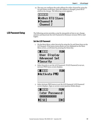
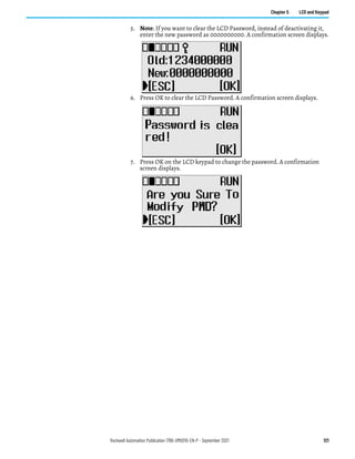
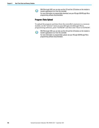
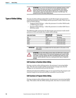
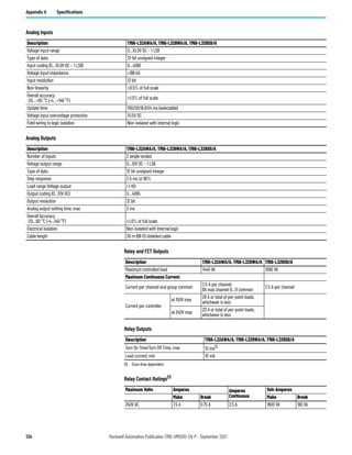
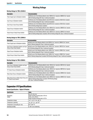
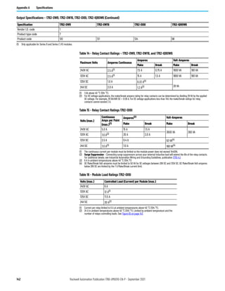
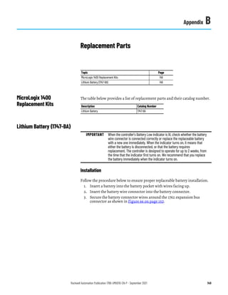
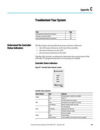
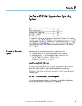
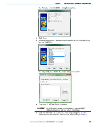
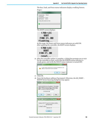
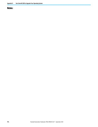
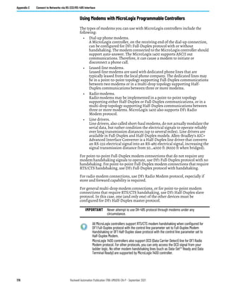
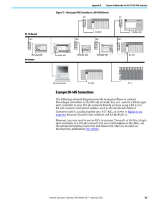
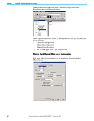
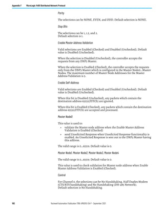
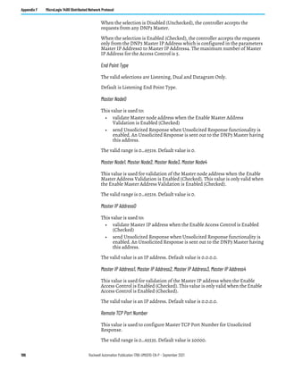
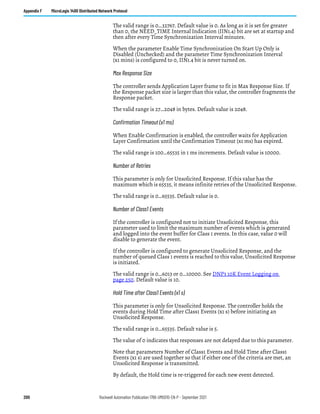
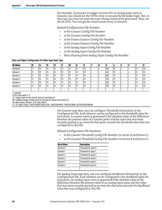
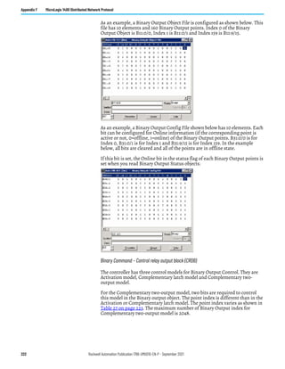
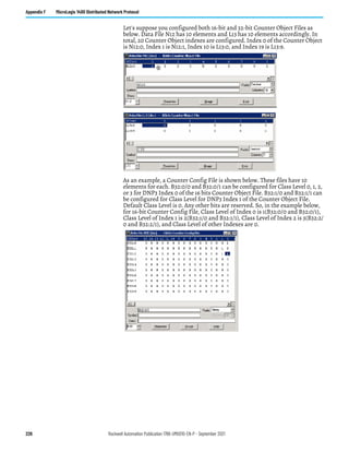
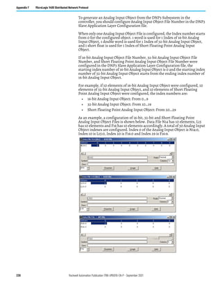
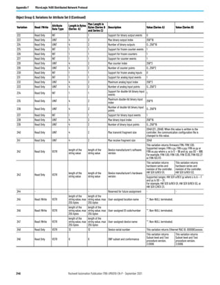
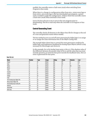
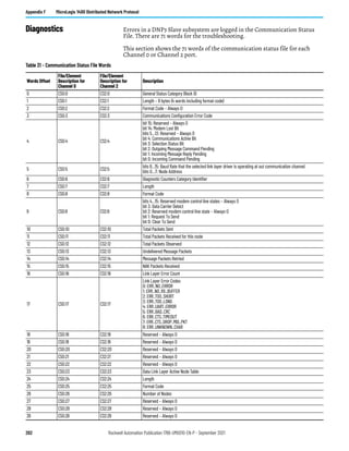
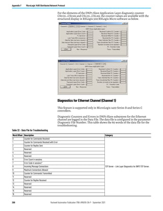
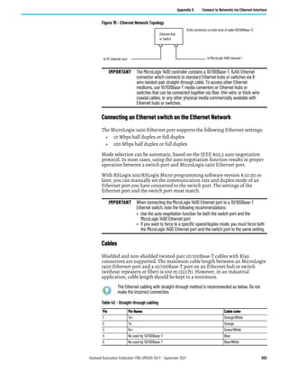
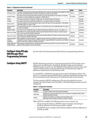
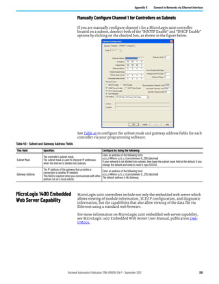
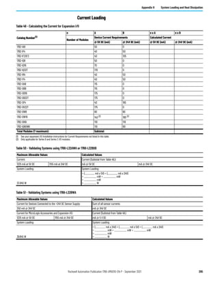
Input Specifications – 1762-IF2OF2, 1762-IF4, 1762-IR4, 1762- IT4
Specification 1762-IF2OF2 1762-IF4 1762-IR4 1762-IT4
Number of inputs 2 differential (unipolar) 4 differential (bipolar) 4 4 input channels plus 1 CJC sensor
Update time (typical) 2.5 ms
130, 250, 290, 450, 530 ms
(selectable)
Input filter and configuration
dependent
NA
A/D converter type Successive approximation Successive approximation Delta-Sigma Delta-Sigma
Common mode voltage range(1) ±27V ±27V NA ±10V
Common mode rejection(2) > 55 dB at 50 and 60 Hz > 55 dB at 50 and 60 Hz
>110 dB at 50 Hz (with 10 or 50 Hz
filter)
>110 dB at 60 Hz (with 10 or 60 Hz
filter)
>110 dB at 50 Hz (with 10 or 50 Hz
filter)
>110 dB at 60 Hz (with 10 or 60 Hz
filter)
Non-linearity (in percent full scale) ±0.12% (3) ±0.12% (2) ±0.05% NA
Typical overall accuracy(4) ±0.55% full scale at -20…65 °C(2)
±0.3% full scale at 25 °C
±0.32% full scale at -20…65 °C (2)
±0.24% full scale at 25 °C
±0.5 °C (F °) for Pt 385 NA
Input impedance
Voltage Terminal: 200 KΩ
Current Terminal: 250 Ω
Voltage Terminal: 200 KΩ
Current Terminal: 275 Ω
>10 ΜΩ >10 ΜΩ
Current input protection ±32 mA ±32 mA NA NA
Voltage input protection ±30V ±30V NA NA
Channel diagnostics
Over or under range or open
circuit condition by bit reporting
for analog inputs.
Over or under range or open
circuit condition by bit reporting
for analog inputs.
Over or under range or open
circuit condition by bit reporting
for analog inputs.
Over or under range or open
circuit condition by bit reporting
for analog inputs.
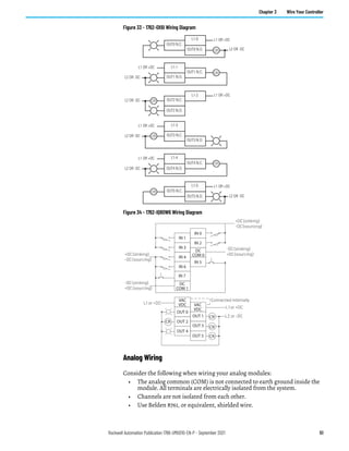
(1) For proper operation, both the plus and minus input terminals must be within ±27V (±10V for 1762-IT4) of analog common.
(2) Vcm = 1 Vpk-pk AC
(3) Only applicable for Series B and Series C I/O modules.
(4) Vcm = 0 (includes offset, gain, non-linearity and repeatability error terms)
Input Specifications 1762-IR4
Specification 1762-IR4
Input types
100 Ω Platinum 385
200 Ω Platinum 385
500 Ω Platinum 385
1,000 Ω Platinum 385
100 Ω Platinum 3916
200 Ω Platinum 3916
500 Ω Platinum 3916
1,000 Ω Platinum 3916
10 Ω Copper 426
120 Ω Nickel 672
120 Ω Nickel 618
604 Ω Nickel-Iron 518
0...150 Ω
0...500 Ω
0...1,000 Ω
0...3,000 Ω
Heat dissipation 1.5 Total Watts (The Watts per point, plus the minimum Watts, with all points enabled.)
Normal mode rejection ratio
70 dB minimum at 50 Hz with the 10 or 50 Hz filter selected
70 dB minimum at 60 Hz with the 10 or 60 Hz filter selected
Typical accuracy [Auto-calibration enabled] at 25 ° C
(77 °F) ambient with module operating temperature
at 25 °C (77 °F) (1)
±0.5 °C (°F) for Pt 385
±0.4 °C (°F) for Pt 3916
±0.2 °C (°F) for Ni
±0.3 °C (°F) for NiFe
±0.6 °C (°F) for Cu
±0.15 Ω for 150 Ω range
±0.5 Ω for 500 Ω range
±1.0 Ω for 1,000 Ω range
±1.5 Ω for 3,000 Ω range
Typical accuracy [Auto-calibration enabled]
at 0…55 ° C (32…131 °F)(1)
±0.9 °C (°F) for Pt 385
±0.8 °C (°F) for Pt 3916
±0.4 °C (°F) for Ni
±0.5 °C (°F) for NiFe
±1.1 °C (°F) for Cu
±0.25 Ω for 150 Ω range
±0.8 Ω for 500 Ω range
±1.5 Ω for 1,000 Ω range
±2.5 Ω for 3,000 Ω range
Accuracy drift at 0…55 ° C (32…131 °F)
±0.026 °C/°C (0.026 °F/°F) for Pt 385
±0.023 °C/°C (0.023 °F/°F) for Pt 3916
±0.012 °C/°C (0.012 °F/°F) for Ni
±0.015 °C/°C (0.015 °F/°F) for NiFe
±0.032 °C/°C (0.032 °F/°F) for Cu
±0.007 Ω/°C (0.012 Ω/°F) for 150 Ω range
±0.023 Ω/°C (0.041 Ω/°F) for 500 Ω range
±0.043 Ω/°C (0.077 Ω/°F) for 1,000 Ω range
±0.07 Ω/°C (0.130 Ω/°F) for 3,000 Ω range](https://image.slidesharecdn.com/1766-um001-en-p-220627062718-6f013ed5/85/Manual-de-PLC-Micrologix-1400-pdf-145-320.jpg)
![146 Rockwell Automation Publication 1766-UM001O-EN-P - September 2021
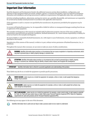
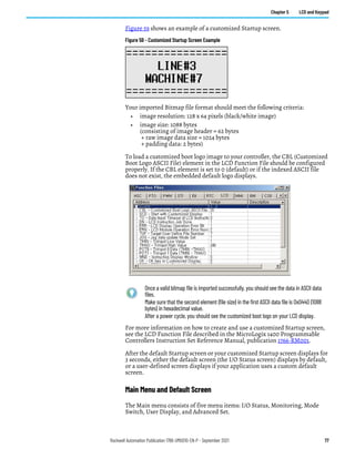
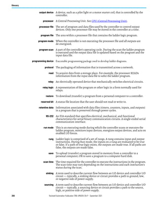
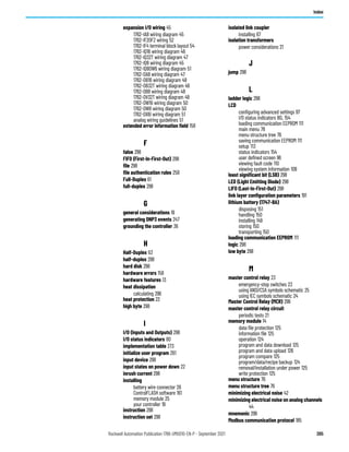
Appendix A Specifications
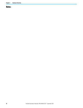
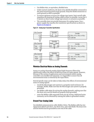
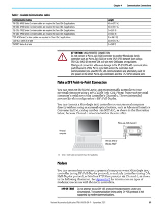
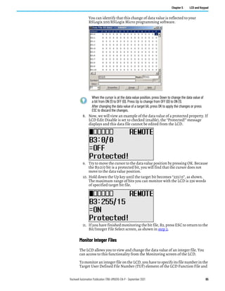
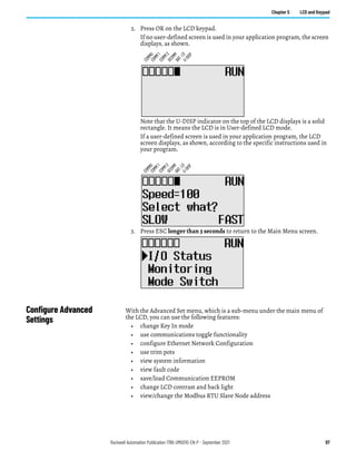
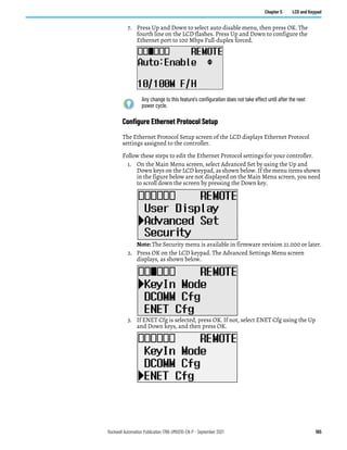
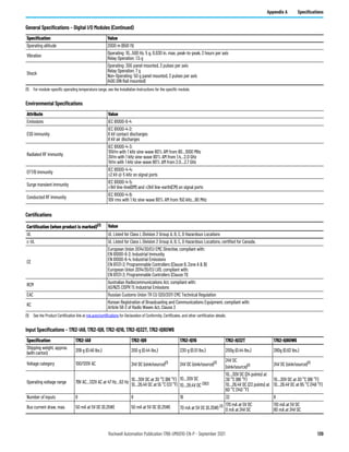
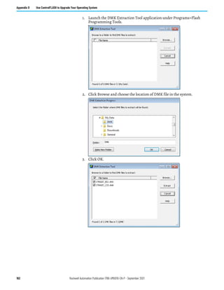
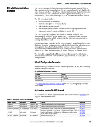
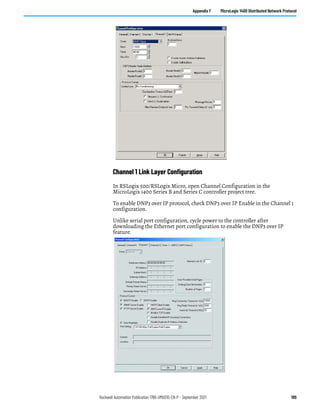
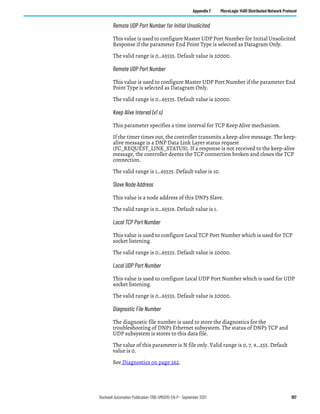
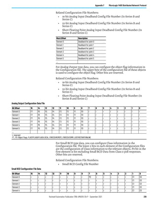
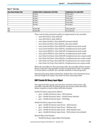
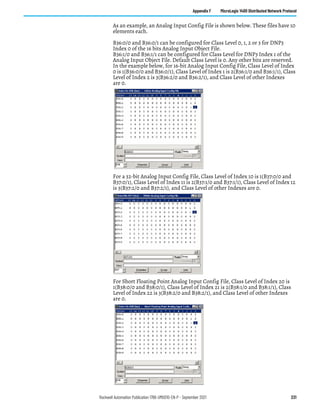
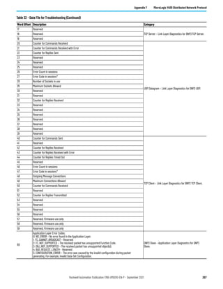
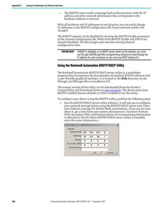
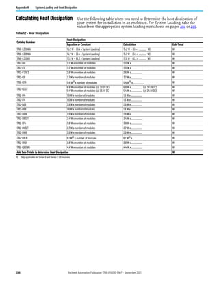
Excitation current source 0.5 mA and 1.0 mA selectable per channel
Open-circuit detection time(2) 6…1212 ms
Input channel configuration
Via configuration software screen or the user program (by writing a unique bit pattern into the module’s configuration
file). See your controller’s user manual to determine if user program configuration is supported.
Calibration
The module performs auto-calibration on channel enable and on a configuration change between channels. You can also
program the module to calibrate every five minutes.
Maximum overload at input terminals ±35V DC continuous
Cable impedance, max. 25 Ω − Operating with >25 Ω will reduce accuracy.
Channel to channel isolation ±10V DC
(1) Accuracy is dependent upon the Analog/Digital converter filter rate selection, excitation current selection, data format, and input noise.
(2) Open-circuit detection time is equal to channel update time.
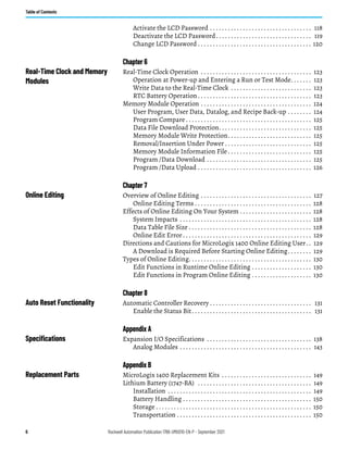
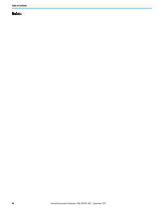
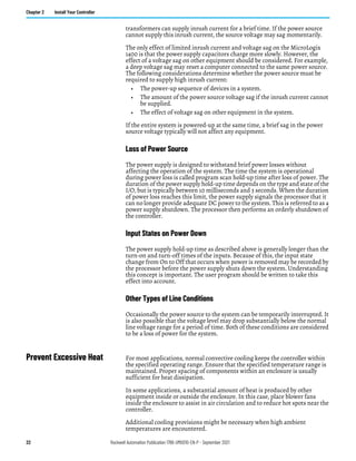
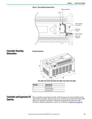
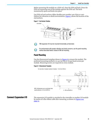
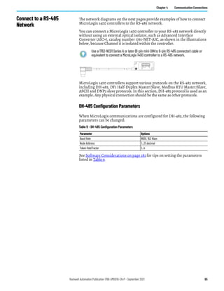
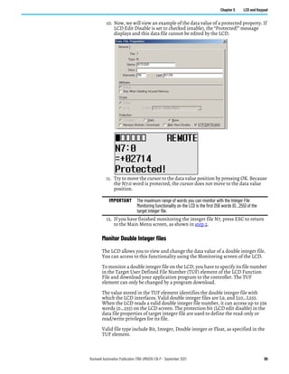
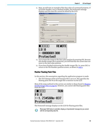
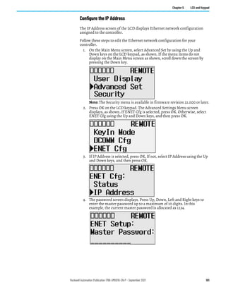
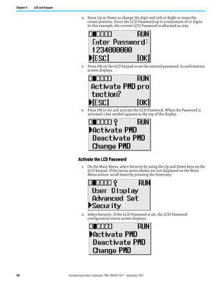
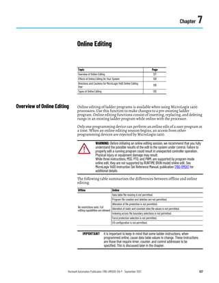
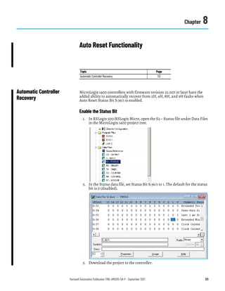
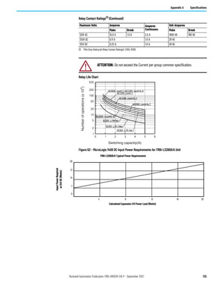
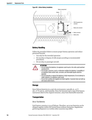
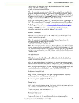
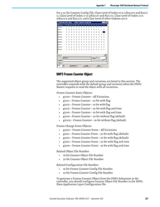
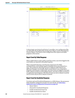
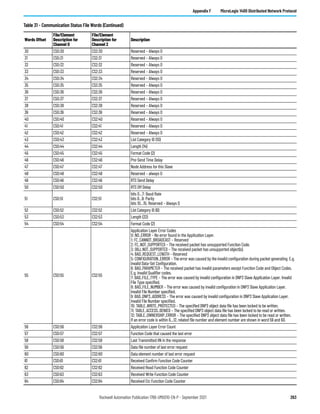
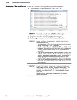
Input Specifications 1762-IR4 (Continued)
Specification 1762-IR4
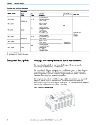
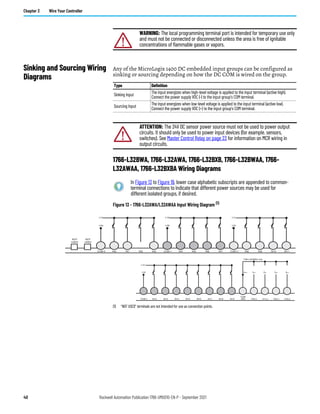
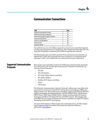
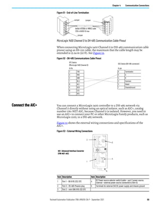
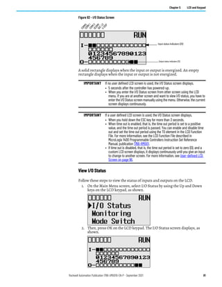
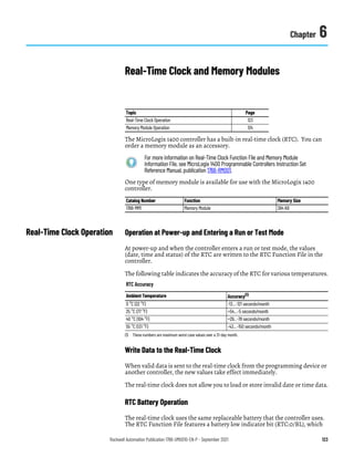
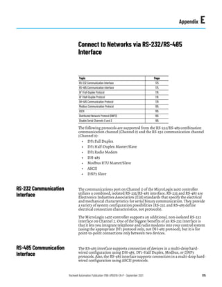
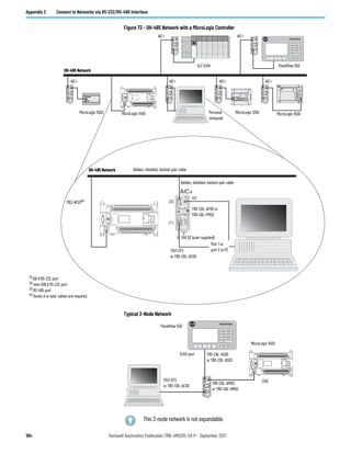
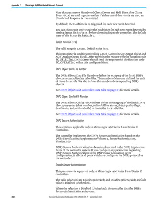
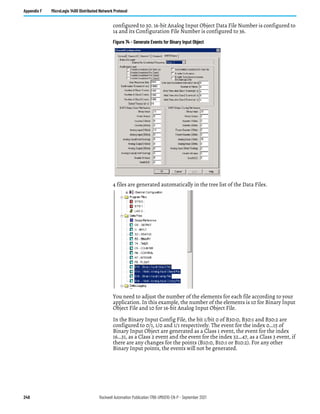
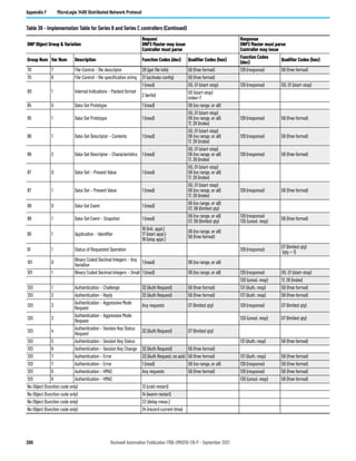
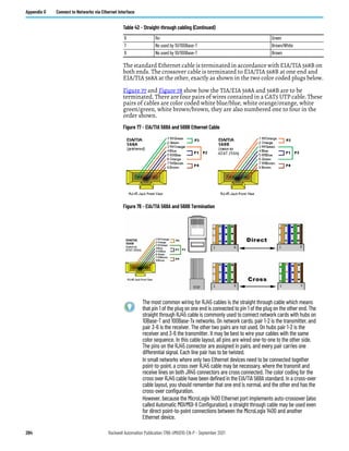
Input Specifications 1762-IT4
Specification Value
Heat dissipation 1.5 Total Watts (The Watts per point, plus the minimum Watts, with all points energized.)
Response speed per channel Input filter and configuration dependent.
Rated working voltage(1) 30V AC/30V DC
Normal mode rejection ratio
85 dB (minimum) at 50 Hz (with 10 Hz or 50 Hz filter)
85 dB (minimum) at 60 Hz (with 10 Hz or 60 Hz filter)
Cable impedance, max. 25 Ω (for specified accuracy)
Open-circuit detection time 7 ms…1.515 s(2)
Calibration
The module performs auto-calibration upon power-up and whenever a channel is enabled. You can also
program the module to calibrate every five minutes.
CJC accuracy ±1.3 °C (±2.34 °F)
Maximum overload at input terminals ±35V DC continuous(3)
Input channel configuration
via configuration software screen or the user program (by writing a unique bit pattern into the module’s
configuration file).
(1) Rated working voltage is the maximum continuous voltage that can be applied at the input terminal, including the input signal and the value that floats above ground potential (for example, 30V DC
input signal and 20V DC potential above ground).
(2) Open-circuit detection time is equal to the module scan time, which is based on the number of enabled channels, the filter frequency of each channel, and whether cyclic calibration is enabled.
(3) Maximum current input is limited due to input impedance.
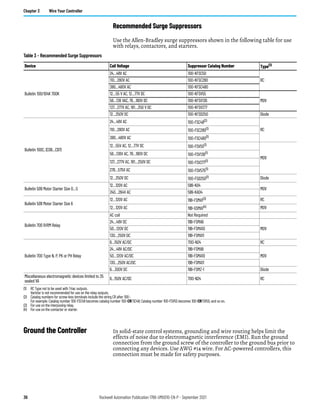
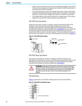
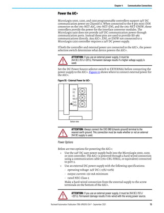
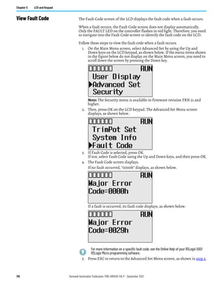
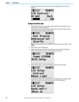
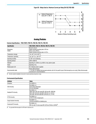
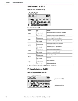
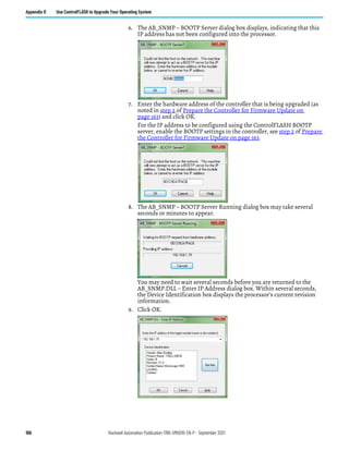
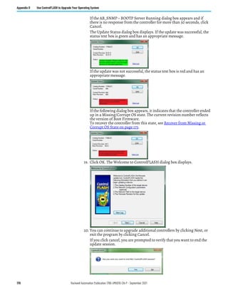
Table 17 - 1762-IT4 Repeatability at 25 °C (77 °F)(1) (2)
(1) Repeatability is the ability of the input module to register the same reading in successive measurements for the same input signal.
(2) Repeatability at any other temperature in the 0...60 °C (32...140 °F) range is the same as long as the temperature is stable.
Input Type Repeatability for 10 Hz Filter
Thermocouple J ±0.1 °C [±0.18 °F]
Thermocouple N (-110…1300 °C [-166…2372 °F]) ±0.1 °C [±0.18 °F]
Thermocouple N (-210…-110 °C [-346…-166 °F]) ±0.25 °C [±0.45 °F]
Thermocouple T (-170…400 °C [-274…752 °F]) ±0 .1 °C [±0.18 °F]
Thermocouple T (-270…-170 °C [-454…-274 °F]) ±1.5 °C [±2.7 °F]
Thermocouple K (-270…1370 °C [-454 °F…2498 °F]) ±0.1 °C [±0.18 °F]
Thermocouple K (-270…-170 °C [-454…-274 °F]) ±2.0 °C [±3.6 °F]
Thermocouple E (-220…1000 °C [-364…1832 °F]) ±0.1 °C [±0.18 °F]
Thermocouple E (-270…-220 °C [-454…-364 °F]) ±1.0 °C [±1.8 °F]
Thermocouples S and R ±0.4 °C [±0.72 °F]
Thermocouple C ±0.2 °C [±0.36 °F]
Thermocouple B ±0.7 °C [±1.26 °F]
±50 mV ±6 μV
±100 mV ±6 μV](https://image.slidesharecdn.com/1766-um001-en-p-220627062718-6f013ed5/85/Manual-de-PLC-Micrologix-1400-pdf-146-320.jpg)
![Rockwell Automation Publication 1766-UM001O-EN-P - September 2021 147
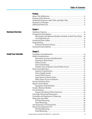
Appendix A Specifications
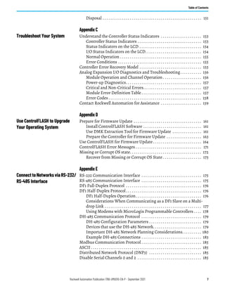
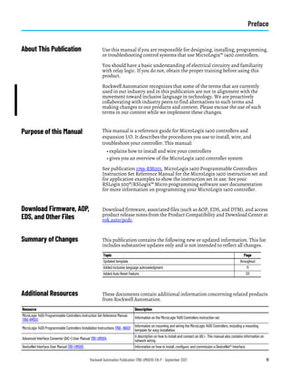
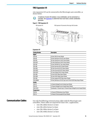
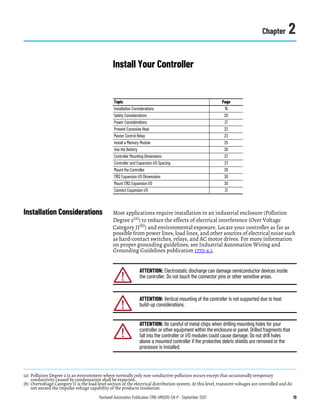
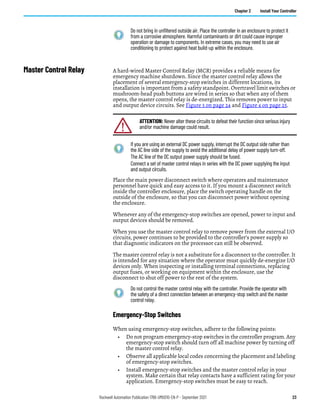
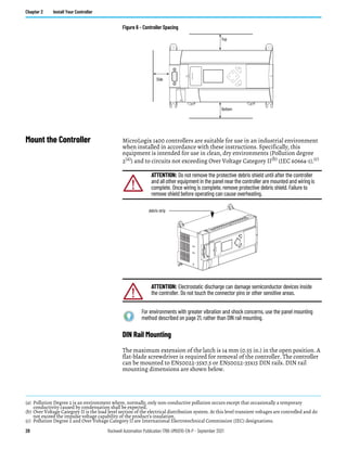
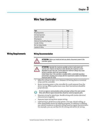
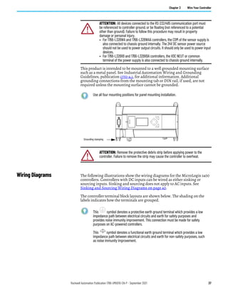
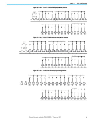
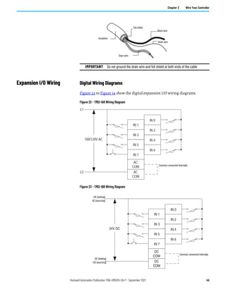
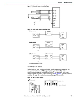
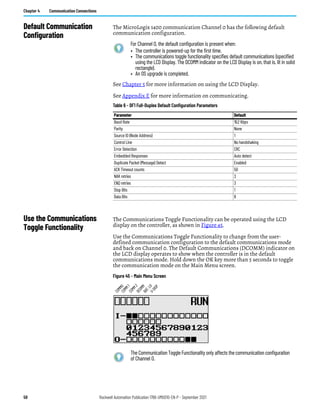
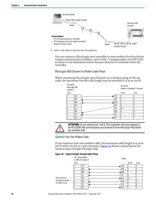
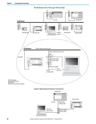
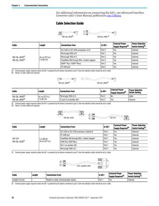
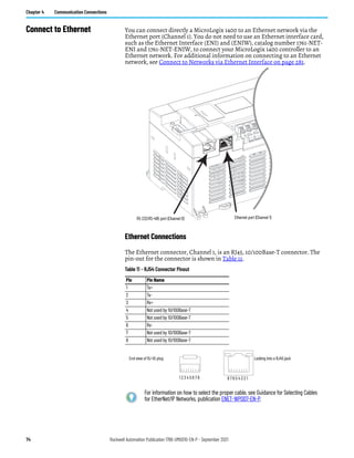
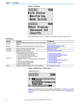
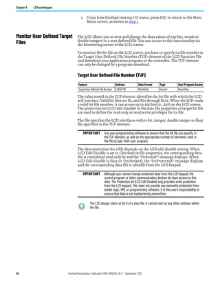
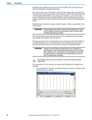
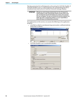
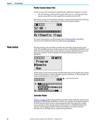
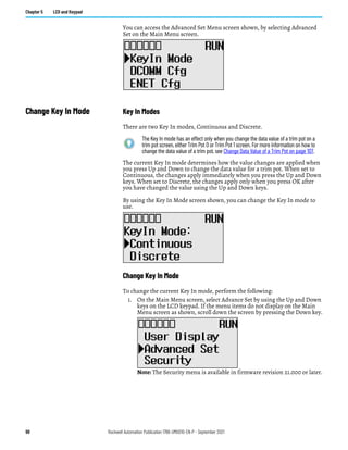
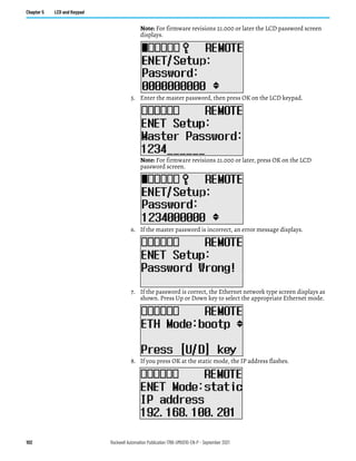
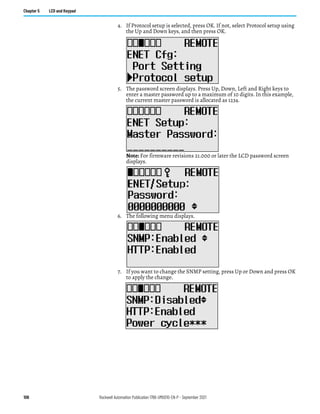
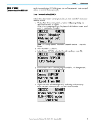
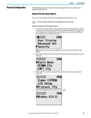
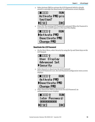
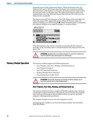
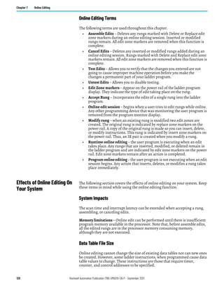
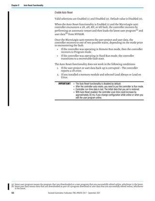
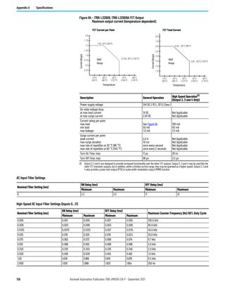
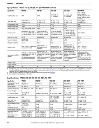
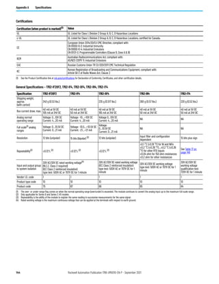
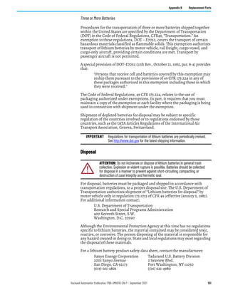
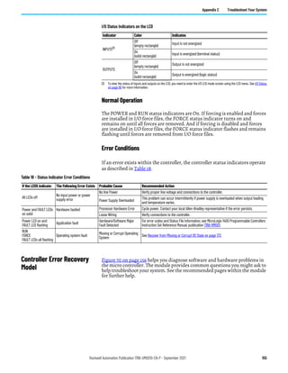
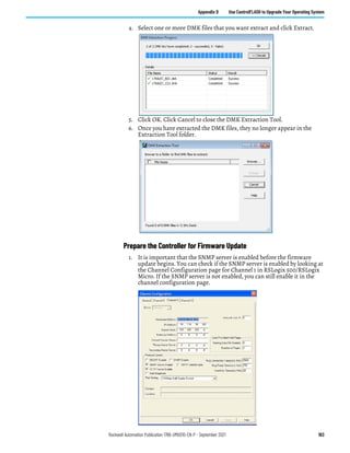
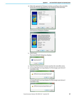
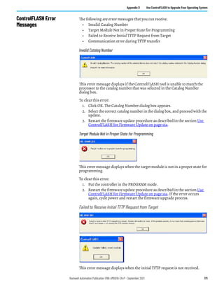
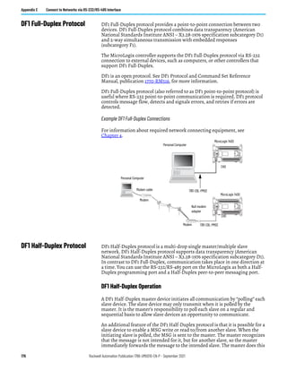
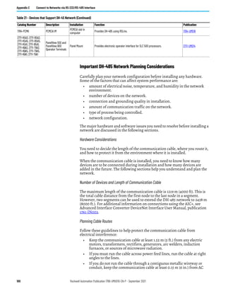
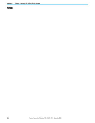
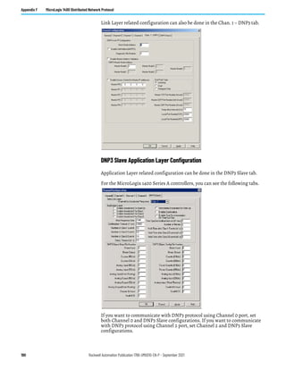
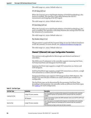
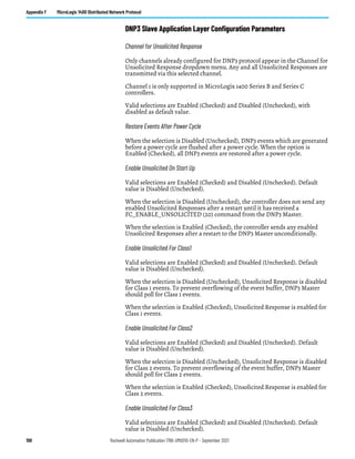
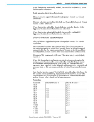
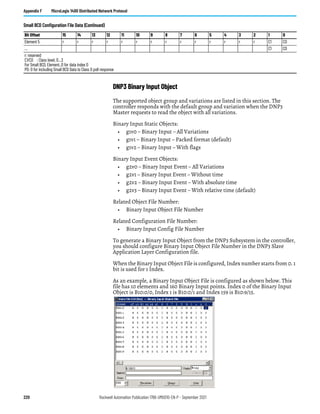
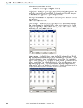
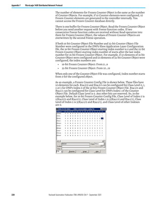
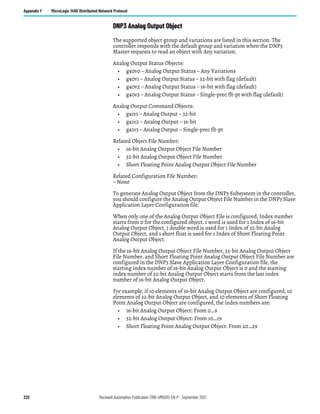
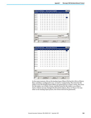
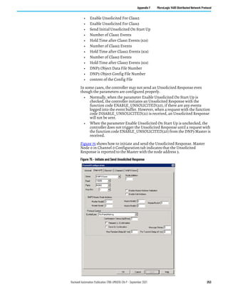
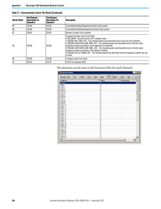
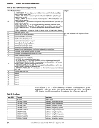
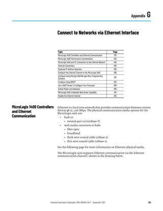
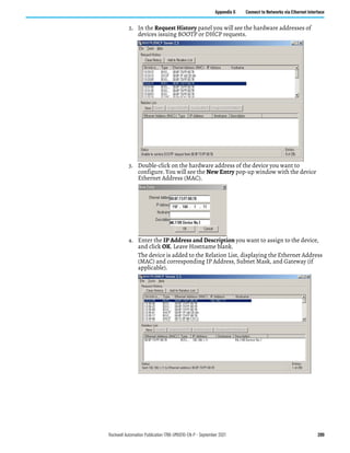
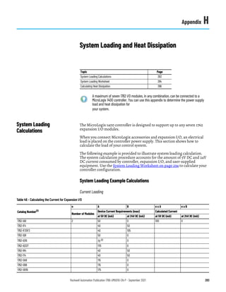
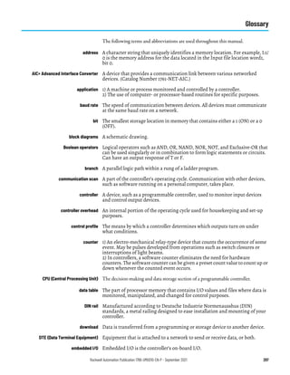
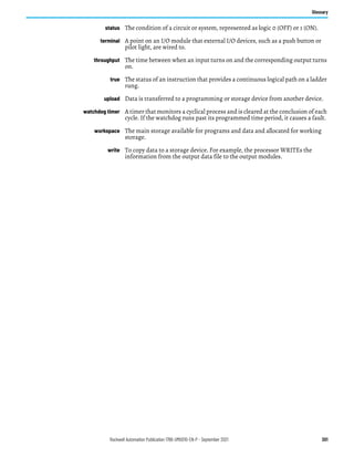
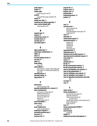
1762-IT4 Accuracy
Input Type(1)
With Auto-calibration Enabled Without Auto-calibration
Accuracy for 10 Hz, 50 Hz and 60 Hz Filters (max.) Maximum Temperature Drift (2)
at 25 °C [77 °F]
Ambient
at 0…60 °C
[32…140 °F] Ambient
at 0…60 °C [32…140 °F]
Ambient
Thermocouple J (-210…1200 °C [-346…2192 °F]) ±0.6 °C [± 1.1 °F] ±0.9 °C [± 1.7 °F] ±0.0218 °C/ °C [±0.0218 °F/ °F]
Thermocouple N (-200…1300 °C [-328…2372 °F]) ±1 °C [± 1.8 °F] ±1.5 °C [±2.7 °F] ±0.0367 °C/ °C [±0.0367 °F/ °F]
Thermocouple N (-210…-200 °C [-346…-328 °F]) ±1.2 °C [±2.2 °F] ±1.8 °C [±3.3 °F] ±0.0424 °C/ °C [±0.0424 °F/ °F]
Thermocouple T (-230…400 °C [-382…752 °F]) ±1 °C [± 1.8 °F] ±1.5 °C [±2.7 °F] ±0.0349 °C/ °C [±0.0349 °F/ °F]
Thermocouple T (-270…-230 °C [-454…-382 °F]) ±5.4 °C [± 9.8 °F] ±7.0 °C [±12.6 °F] ±0.3500 °C/ °C [±0.3500 °F/ °F]
Thermocouple K (-230…1370 °C [-382…2498 °F]) ±1 °C [± 1.8 °F] ±1.5 °C [±2.7 °F] ±0.4995 °C/ °C [±0.4995 °F/ °F]
Thermocouple K (-270…-225 °C [-454…-373 °F]) ±7.5 °C [± 13.5 °F] ±10 °C [± 18 °F] ±0.0378 °C/ °C [±0.0378 °F/ °F]
Thermocouple E (-210…1000 °C [-346…1832 °F]) ±0.5 °C [± 0.9 °F] ±0.8 °C [±1.5 °F] ±0.0199 °C/ °C [±0.0199 °F/ °F]
Thermocouple E (-270…-210 °C [-454…-346 °F]) ±4.2 °C [± 7.6 °F] ±6.3 °C [±11.4 °F] ±0.2698 °C/ °C [±0.2698 °F/ °F]
Thermocouple R ±1.7 °C [± 3.1 °F] ±2.6 °C [± 4.7 °F] ±0.0613 °C/ °C [±0.0613 °F/ °F]
Thermocouple S ±1.7 °C [± 3.1 °F] ±2.6 °C [± 4.7 °F] ±0.0600 °C/ °C [±0.0600 °F/ °F]
Thermocouple C ±1.8 °C [±3.3 °F] ±3.5 °C [±6.3 °F] ±0.0899 °C/ °C [±0.0899 °F/ °F]
Thermocouple B ±3.0 °C [±5.4 °F] ±4.5 °C [±8.1 °F] ±0.1009 °C/ °C [±0.1009 °F/ °F]
±50 mV ±15 μV ±25 μV ±0.44μV/ °C [±0.80μV/ °F]
±100 mV ±20 μV ±30 μV ±0.69μV/ °C [±01.25μV/ °F]
(1) The module uses the National Institute of Standards and Technology (NIST) ITS-90 standard for thermocouple linearization.
(2) Temperature drift with auto-calibration is slightly better than without auto-calibration.
For more detailed 1762-IT4 accuracy information, see publication 1762-UM002.
Output Specifications – 1762-IF2OF2, 1762-OF4
Specification 1762-IF2OF2 1762-OF4
Number of outputs 2 single-ended (unipolar) 4 single-ended (unipolar)(2)
Update time (typical) 4.5 ms
D/A converter type Resistor string R-2R Ladder Voltage Switching
Resistive load on current output 0…500 Ω (includes wire resistance) 0…500 Ω (includes wire resistance)
Load range on voltage output > 1 kΩ > 1 KΩ
Reactive load, current output < 0.1 mH < 0.1 mH
Reactive load, voltage output < 1 μF < 1 μF
Typical overall accuracy(1) ±1.17% full scale at -20…65 °C (2)
±0.5% full scale at 25 °C
±1.17% full scale at -20…65 °C (2)
±0.5% full scale at 25 °C
Output ripple
range 0…500 Hz
(see output range)
< ±0.1% < ±0.1%
Non-linearity (in percent full scale) < ±0.59% (2)
< ±0.59% (2)
Open and short-circuit protection Continuous Continuous
Output protection ±32 mA ±32 mA
(1) Includes offset, gain, non-linearity and repeatability error terms.
(2) Only applicable for Series B and Series C I/O modules.
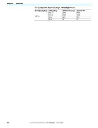
Valid Input/Output Data Word Formats/Ranges – 1762-IF2OF2
Normal Operating Range Full Scale Range RAW/Proportional Data Scaled-for-PID
0…10V DC
10.5V DC 32760 16380
0.0V DC 0 0](https://image.slidesharecdn.com/1766-um001-en-p-220627062718-6f013ed5/85/Manual-de-PLC-Micrologix-1400-pdf-147-320.jpg)


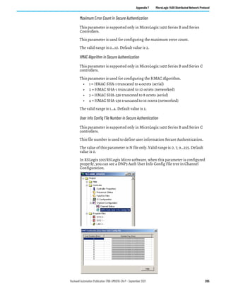
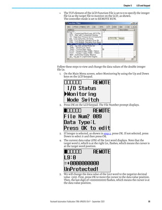
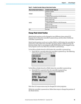
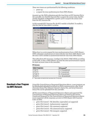
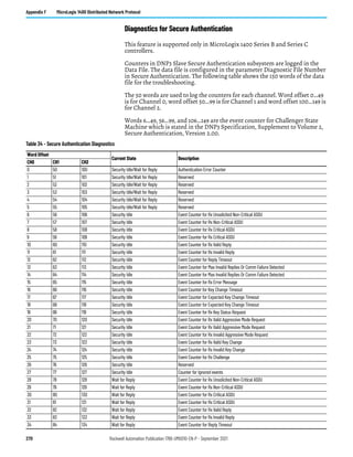
![Rockwell Automation Publication 1766-UM001O-EN-P - September 2021 209
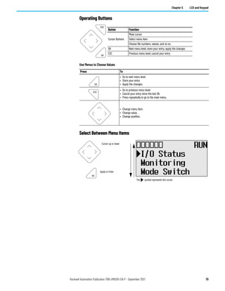
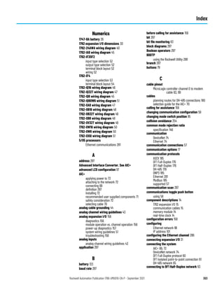
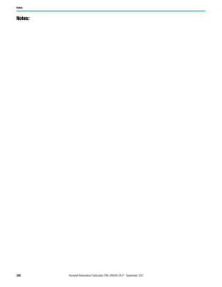
Appendix F MicroLogix 1400 Distributed Network Protocol
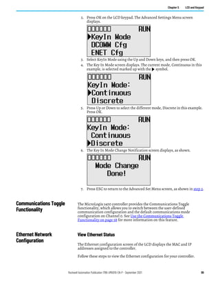
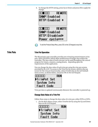
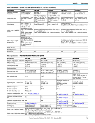
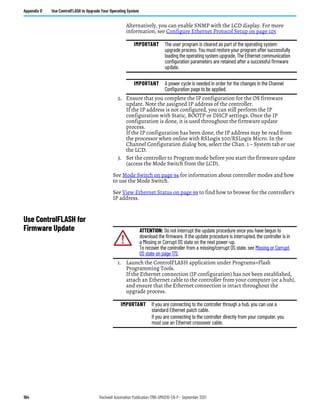
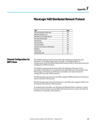
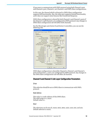
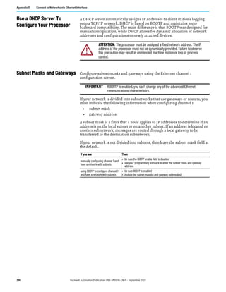
2. Click Apply and OK.
3. Perform a power cycle in order for the changes to take effect.
The controller does not allow any incoming EtherNet/IP connections
anymore. This means that you cannot use RSLogix 500/RSLogix Micro
over Ethernet port to monitor or change the configuration/user
program.
For more information about Ethernet Port Disable, see MicroLogix 1400
Programmable Controllers Instruction Set Reference Manual,
publication 1766-RM001.
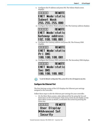
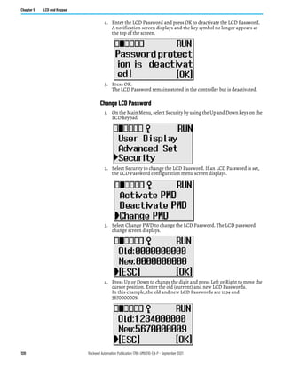
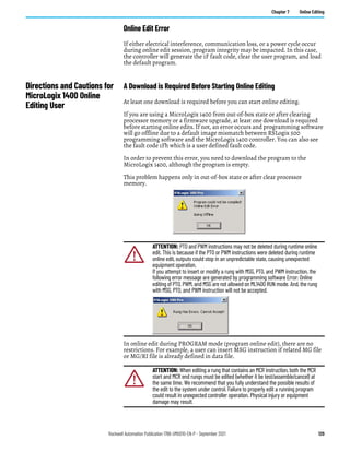
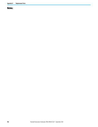
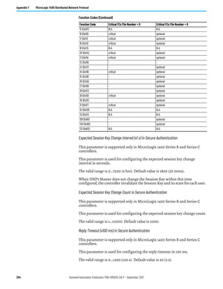
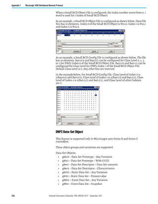
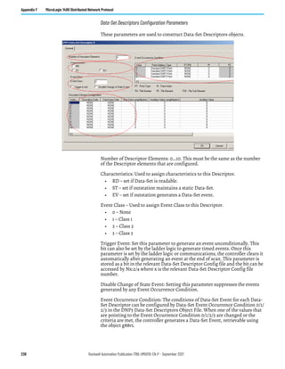
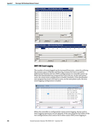
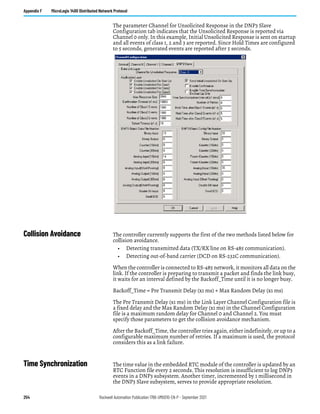
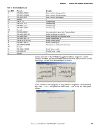
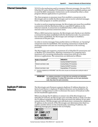
DNP3 Slave Application
Layer
This section covers DNP3 Slave Application Layer Function Codes and Internal
Indications.
For details of Packet Formats for the request and response, see the DNP3
Protocol specifications.
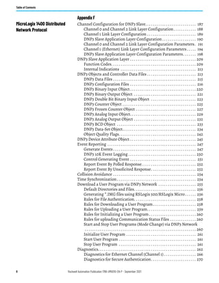
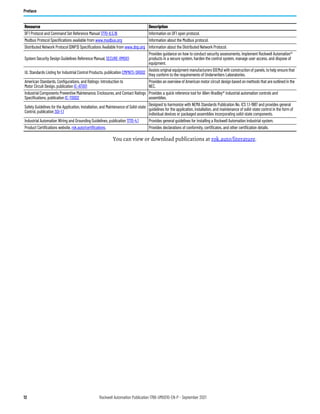
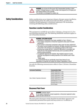
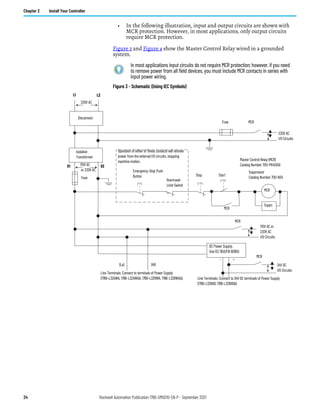
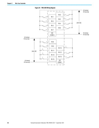
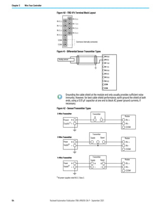
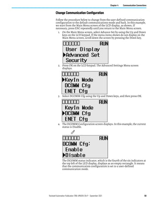
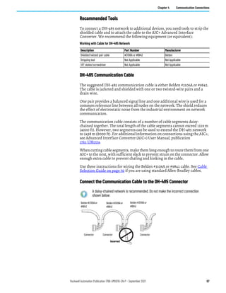
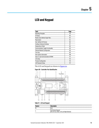
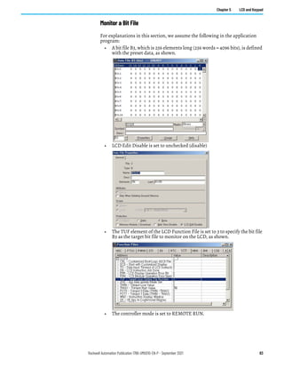
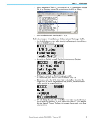
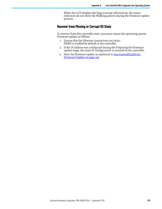
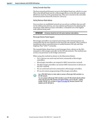
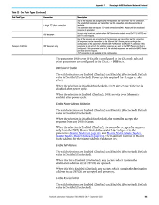
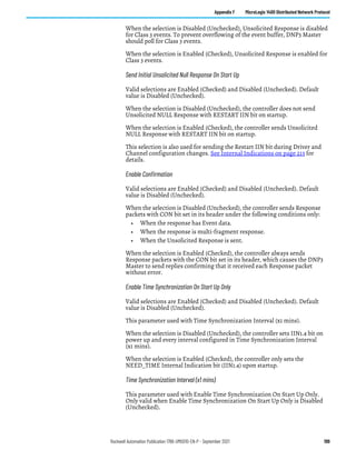
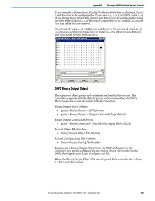
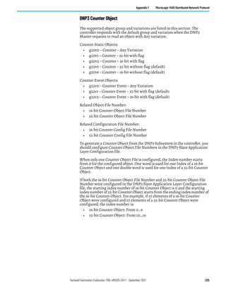
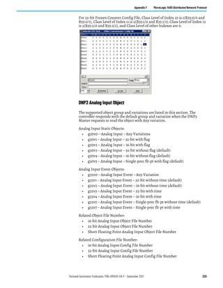
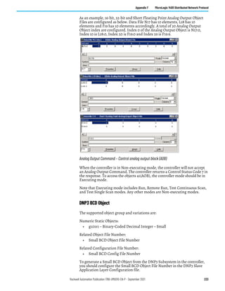
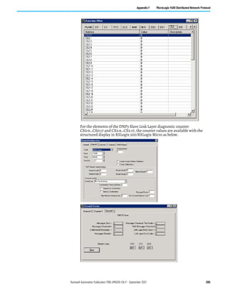
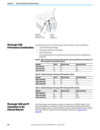
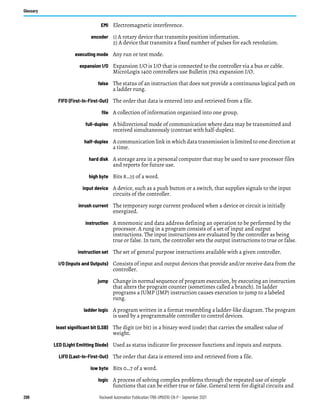
Function Codes
FC_CONFIRM (FC Byte = 0x00)
00 – Confirm
A DNP3 master sends a message with this function code to confirm receipt of a
response fragment. In a general environment, the controller receives a
response with this function code. But the controller may generate a response
with this function code when a DNP3 Master sends a request with the CON bit
set in the application control header.
FC_READ (FC Byte = 0x01)
01 – Read
The READ function code is used by a DNP3 master to request data from the
controller.
FC_WRITE (FC Byte = 0x02)
02 – Write
The WRITE function code is used to write the contents of DNP3 objects from
the DNP3 master to the controller. This function code is used for clearing bit
IIN1.7 [DEVICE_RESTART], setting time in the controller and downloading
user programs to the controller.
FC_SELECT (FC Byte = 0x03)
03 – Select
The SELECT function code is used in conjunction with the OPERATE function
code as part of select-before-operate method for issuing control requests. This
procedure is used for controlling binary output (CROB) or analog output
(AOB) objects.
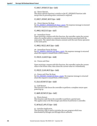
FC_OPERATE (FC Byte = 0x04)
04 – Operate
See FC_SELECT (FC Byte = 0x03) on page 209.](https://image.slidesharecdn.com/1766-um001-en-p-220627062718-6f013ed5/85/Manual-de-PLC-Micrologix-1400-pdf-209-320.jpg)
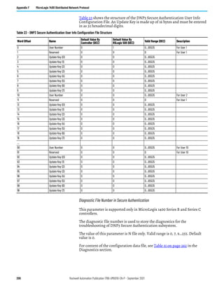
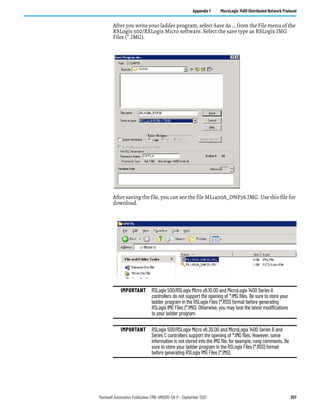
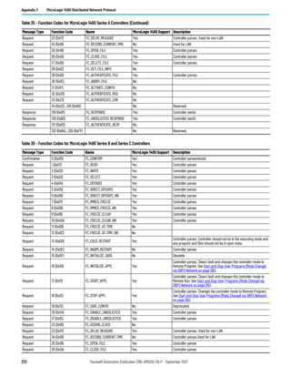
![Rockwell Automation Publication 1766-UM001O-EN-P - September 2021 247
Appendix F MicroLogix 1400 Distributed Network Protocol
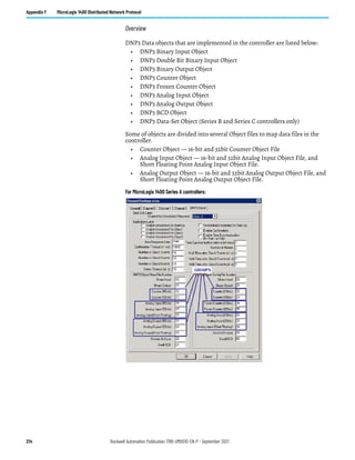
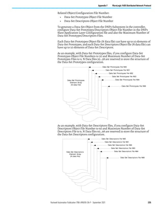
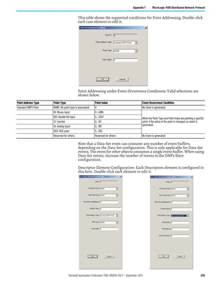
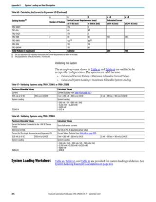
Event Reporting This section covers how to generate DNP3 events from DNP3 Data Objects and
how to report the generated events by polled response or unsolicited response.
Generate Events
The controller has a separate buffer area that you can use to log DNP3 events
internally.
The maximum number of the Events that can be logged is 6013 or 10000 (see
DNP3 10K Event Logging on page 250), regardless of the Event data type. With
Series B and Series C controllers, a Data-Set event can consume multiple
numbers of the event buffers.
If the number of the generated events reaches this value, the controller sets
IIN2.3 [EVENT_BUFFER_OVERFLOW]. Further events are not logged until
the logged events are reported to DNP3 Master and the buffer is available.
The elements CS0:67 or CS2:67 in the Communication status file show how
many events are logged to the event buffer. The logged events are not removed
until they are reported to DNP3 Master successfully. Logged event can also be
cleared when one of the following events occur:
• New OS firmware upgrade
• New user program download.
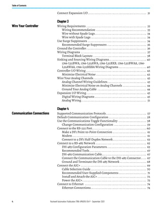
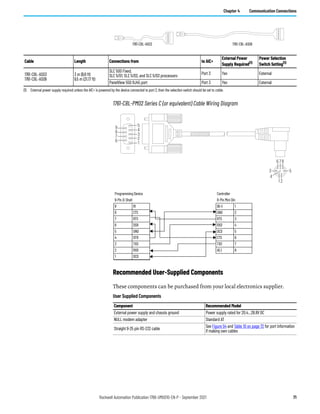
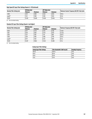
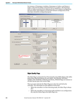
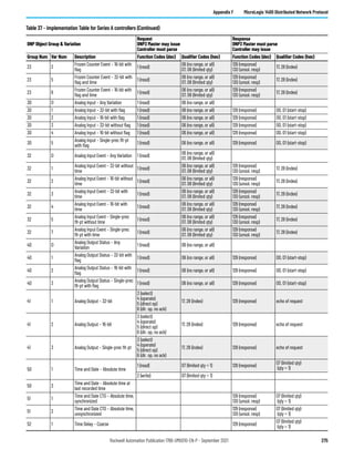
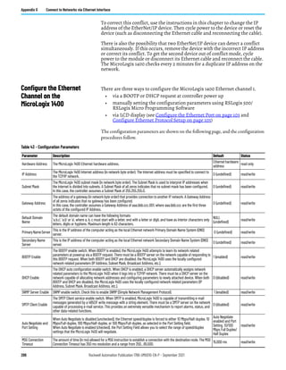
Figure 74 shows how to generate events for a Binary Input Object and a 16-bit
Analog Input Object. In the DNP3 Slave configuration, Binary Input Object
Data File Number is configured to 10 and its Configuration File Number is
250 Read Only VSTR
length of the
string value
length of the
string value
Device manufacturer's product
name and model
This variation returns
Catalog Number and OS
Series of the controller.
1766-L32BWA SER A.
This variation returns
Catalog Number and OS
Series of the controller.
1766-L32BWA SER B.
Supported ranges: 1766-L32xxxa SER y where xxxa is
BWA, AWA, BXB, BWAA, AWAA, or BXBA and y is A ~ F.
For example, 1766-L32BWA SER A, 1766-L32AWA SER
B, 1766-L32BXB SER C, or 1766-L32BWAA SER A.
251 - - - - Reserved for future assignment - -
252 Read Only VSTR 13 19 Device manufacturer's name
This variation returns the
Company name. Allen-
Bradley.
This variation returns the
Company name. Rockwell
Automation for DNP3.
253 Read Only - - - Reserved for future assignment - -
254 Read Only - - - Non-specific all attributes request
This variable returns all of the variations in this group
except this variation.
255 Read Only - - - List of attribute variations
This variation returns the R/W property for each
variation. From g0v211…g0v253.
0 for Read Only
1 for Read or Write
Object Group 0, Variations for Attribute Set 0 (Continued)
Variation Read /Write
Attribute
Data Type
Length in Bytes
(Series A)
Max Length in
Bytes (Series B
and Series C)
Description Value (Series A) Value (Series B)](https://image.slidesharecdn.com/1766-um001-en-p-220627062718-6f013ed5/85/Manual-de-PLC-Micrologix-1400-pdf-247-320.jpg)
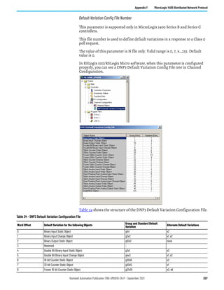
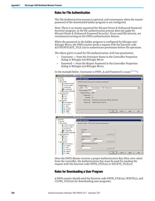
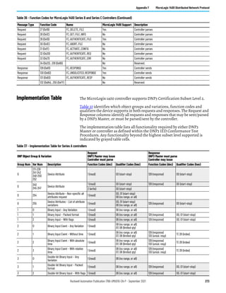
![256 Rockwell Automation Publication 1766-UM001O-EN-P - September 2021
Appendix F MicroLogix 1400 Distributed Network Protocol
• g70v6 File-Control – File transport status: supported
• g70v7 File-Control – File descriptor: supported
• g70v8 File-Control – File specification string: not supported by Series A
controllers, supported by Series B and Series C controllers
• g91v1 Status of Requested Operation – Activate configuration: not
supported by Series A controllers, supported by Series B and Series C
controllers
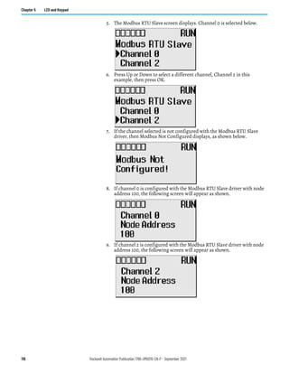
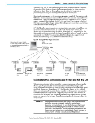
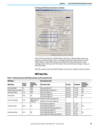
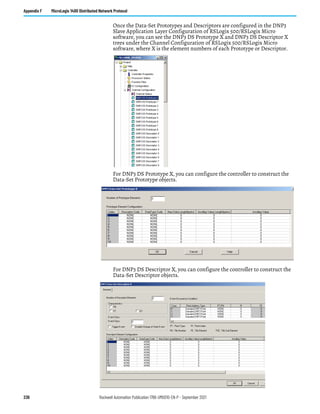
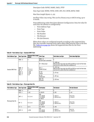
Default Directories and Files
The controller has default directories and files for file handling in a DNP3
subsystem.
The default directories and files can be read from the controller using the
function code OPEN_FILE(25), Read(1), and CLOSE_FILE(26).
Currently supported directories are /EXE and /DIAG. Supported files are listed
in this section. These directories/files cannot be removed and cannot be
created using DNP3 requests.
• The directory/file names must all be in capital letters.
• Root level can only be a directory marker. The directory marker is / for
Series A, or for Series B and Series C.
• Directory level can only contain directories.
• File level can only contain files.
Note that the directory marker is different in MicroLogix 1400 Series A and
Series B and Series C controllers. The directory marker is / for Series A and
for Series B and Series C controllers. In this document, / is used to explain File
Object feature.
Generating *.IMG files using RSLogix 500/RSLogix Micro
Typically, RSLogix 500/RSLogix Micro stores the ladder program as RSLogix™
Files (*.RSS). However, to download a ladder program using a File Object via
DNP3 network, you must save your ladder program in the RSLogix IMG Files
(*.IMG) format.
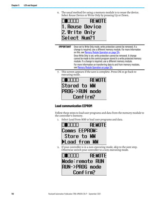
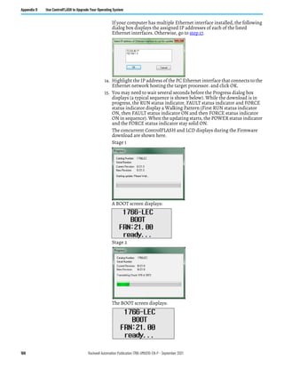
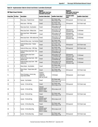
Table 30 - Supported Files and Directories
Root Level Directory Level File Level Full Name String to Access
/ /
EXE /EXE
[processorName].IMG /EXE/[processorName].IMG
DIAG /DIAG
CH0.CSF /DIAG/CH0.CSF
CH1.ESF /DIAG/CH1.ESF
CH2.CSF /DIAG/CH2.CSF](https://image.slidesharecdn.com/1766-um001-en-p-220627062718-6f013ed5/85/Manual-de-PLC-Micrologix-1400-pdf-256-320.jpg)
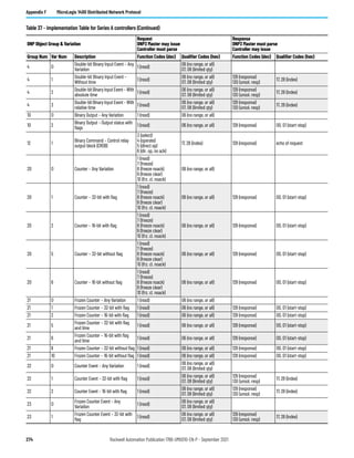
![Rockwell Automation Publication 1766-UM001O-EN-P - September 2021 259
Appendix F MicroLogix 1400 Distributed Network Protocol
When a master sends the function code OPEN_FILE(25) with the file
command object, the file name string in File command object must be in this
directory and file name format:
• /EXE/[processorName].IMG
The directory and file name extension string must all be in capital letters and
the string size cannot be exceed 64 bytes. The file name [processorName] is
from the Processor Name in the Controller Properties dialog in RSLogix 500/
RSLogix Micro.
This ladder program [processorName].IMG is generated from RSLogix 500/
RSLogix Micro. DNP3 Master should send the [processorName].IMG file
without any modification.
When the MicroLogix 1400 Series A controller receives a request with the
function code WRITE(2) for User Program download, the controller activates
all configurations as well as channel configurations after the last application
file segment is received. For the MicroLogix 1400 Series B and Series C
controller, the function code Activate Configuration (0x1F) is supported.
Unlike Series A controller, the MicroLogix 1400 Series B and Series C controller
does not activate all configurations as well as channel configurations after the
last application file segment is received. To activate all configurations, you
need to send a command with the function code, Activate Configuration (0x1F)
after downloading the user program.
Maximum file size is 384 Kbytes. The controller supports downloading up to
256 Kbyte size of user program when Recipe is not configured. When Recipe is
configured, Maximum file size is 384 Kbytes.
The first application segment of the ladder program should be larger than or
equal to the size of System Exe File structure, 64 bytes.
An application segment of the ladder program cannot be exceed 2048 bytes.
When the controller receives the first application segment, it acquires Edit
Resource from the system. If the last application segment is received properly,
the controller returns Edit Resource to the system. After acquiring Edit
Resource, each of the application segments should be received within the Edit
Resource/Owner Timeout.
The controller checks the integrity of the program after receiving the last
application segment. If the downloaded user program fails the integrity check,
controller clears the downloaded user program and restores the default user
program. In this case, the configured Channel configuration is not changed
from the last valid configuration.
A user program cannot be downloaded while the controller is in Executing
mode. Before downloading, send a mode change request with the function
code STOP_APPL(18). See Start and Stop User Programs (Mode Change) via
DNP3 Network on page 260 for more details.
Executing modes include Run, Remote Run, Test Continuous Scan, and Test
Single Scan modes. Any others are Non-executing modes.
Rules for Uploading a User Program
A DNP3 master should send the function code OPEN_FILE(25), READ(1), and
CLOSE_FILE(26) for uploading user programs.](https://image.slidesharecdn.com/1766-um001-en-p-220627062718-6f013ed5/85/Manual-de-PLC-Micrologix-1400-pdf-259-320.jpg)
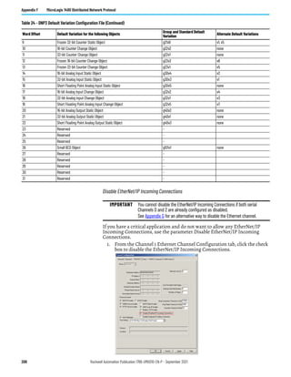
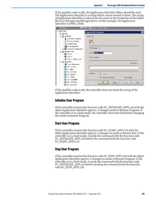
![260 Rockwell Automation Publication 1766-UM001O-EN-P - September 2021
Appendix F MicroLogix 1400 Distributed Network Protocol
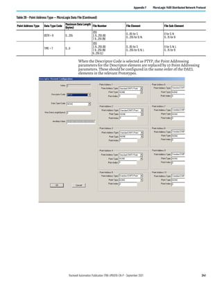
When a master sends the function code OPEN_FILE(25) with the file
command object, the file name string in File command object must be in this
directory and file name format:
• /EXE/[processorName].IMG
The directory and file name extension string must all be in capital letters and
the string size cannot be exceed 64 bytes. The file name [processorName] is
from the Processor Name in the Controller Properties dialog in RSLogix 500/
RSLogix Micro.
The maximum file size is 384 Kbytes. The controller supports uploading of user
programs up to 256 Kbyte in size when Recipe is not configured. When Recipe
is configured, Maximum file size is 384 Kbytes.
The first application segment of the ladder program should be larger than or
equal to the size of System Exe File structure, 64 bytes.
An application segment of the ladder program cannot be exceed 2048 bytes.
Rules for Initializing a User Program
A DNP3 master should send the function code DELETE_FILE(27) for
initializing user programs.
When controller receives a request with the function code DELETE_FILE(27),
it clears the current user program which was downloaded into the controller,
and restores the default user program.
User programs cannot be initialized while the controller is in Executing mode.
Before initializing programs, a mode change request should be sent with the
function code STOP_APPL(18).
Rules for uploading Communication Status Files
A DNP3 master should send the function code OPEN_FILE(25), READ(1), and
CLOSE_FILE(26) for uploading Communication Status Files.
The function code WRITE(2) for downloading Communication Status Files is
not supported.
The file name should be /DIAG/CH0.CSF, /DIAG/CH1.ESF, and /DIAG/
CH2.CSF for Channel 0, Channel 1, and Channel 2 respectively.
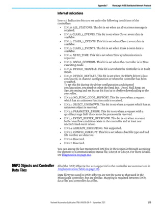
Start and Stop User Programs (Mode Change) via DNP3 Network
This section covers how to change the controller mode via DNP3 network.
To change the controller mode, use the function codes FC_INITIALIZE_APPL
(16), FC_START_APPL (17) and FC_STOP_APPL (18).](https://image.slidesharecdn.com/1766-um001-en-p-220627062718-6f013ed5/85/Manual-de-PLC-Micrologix-1400-pdf-260-320.jpg)


This document provides instructions for installing, wiring, and configuring communication for a MicroLogix 1400 programmable controller. It includes safety considerations for installation, guidelines for mounting the controller and expansion I/O, wiring diagrams, and information on supported communication protocols. Proper installation and wiring are required to ensure safe operation of the controller system. The document contains important warnings and cautions that must be followed.


