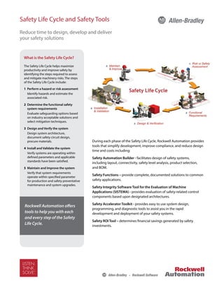
Safety Life Cycle and Safety Tools
Reduce time to design, develop and deliver
your safety solutions
During each phase of the Safety Life Cycle, Rockwell Automation provides
tools that simplify development, improve compliance, and reduce design
time and costs including:
Safety Automation Builder - facilitates design of safety systems,
including layout, connectivity, safety level analysis, product selection,
and BOM.
Safety Functions – provide complete, documented solutions to common
safety applications.
Safety Integrity Software Tool for the Evaluation of Machine
Applications (SISTEMA) - provides evaluation of safety-related control
components based upon designated architectures.
Safety Accelerator Toolkit - provides easy to use system design,
programming, and diagnostic tools to assist you in the rapid
development and deployment of your safety systems.
Safety ROI Tool – determines financial savings generated by safety
investments.
What is the Safety Life Cycle?
The Safety Life Cycle helps maximize
productivity and improve safety by
identifying the steps required to assess
and mitigate machinery risks. The steps
of the Safety Life Cycle include:
1 Perform a hazard or risk assessment
Identify hazards and estimate the
associated risk.
2 Determine the functional safety
system requirements
Evaluate safeguarding options based
on industry acceptable solutions and
select mitigation techniques.
3 Design and Verify the system
Design system architecture,
document safety circuit design,
procure materials.
4 Install and Validate the system
Verify systems are operating within
defined parameters and applicable
standards have been satisfied.
5 Maintain and Improve the system
Verify that system requirements
operate within specified parameter
for production and safety preventative
maintenance and system upgrades.
Rockwell Automation offers
tools to help you with each
and every step of the Safety
Life Cycle.
Safety Automation Builder
The Safety Automation Builder (SAB) tool facilitates planning of safety systems, helps you select products
to achieve the required safety performance level (PL) according to EN ISO 13849-1, and creates SISTEMA
projects for analysis of all Safety Functions. Use SAB to:
•	 Layout machine hazards and access points.
•	 Define safety functions and select safety
products for each.
•	 Export data to SISTEMA for analysis.*
Direct integration to ProposalWorks allows
complete Bills of Material to be generated.
SAB leverages the industry’s most complete
offering of safety products, utilizing widely
accepted best practices to build a complete
safety solution. Outputs of the tool include:
•	 Bills of Material
•	 Conceptual Safety Layout Drawings
•	 Architectural Structure Drawings
•	 ePLAN files
•	 SISTEMA project files*
* SAB and SISTEMA tools must be used in conjunction
with each other to provide this output.
Safety Functions
Safety Functions provide a systematic, building block approach to machine safety utilizing Rockwell
Automation’s broad portfolio of products and industry experience. These documents provide solutions
to common safety applications and allow you to develop safety systems quickly, efficiently, and accurately.
Typical content includes:
•	 Operational description
•	 Electrical drawings
•	 Bill of material
•	 PLC code  relay configuration
instructions
•	 SISTEMA verification calculation
•	 Verification and validation plan
Safety Functions available today
include:
•	 E-stop		
•	 Light Curtains
•	 Two hand control
•	 Enabling Switch
•	 Guard-locking switches
•	 Door interlocks
Additional Safety Functions will be available in the near future.
The latest additions to our suite of safety tools deliver a complete safety solution
while simplifying development, improving compliance, and reducing cost.
GuardLogix® Safety System
Interlock Safety Function
Safety Functional Requirements
Opening of a guard door will stop and prevent hazardous motion by
removal of power to the motor. Upon closing of the door, hazardous
motion and power to the motor will not resume until a secondary
action (start button depressed) occurs. Faults at the door interlock
switch, wiring terminals or safety controller will be detected before the
next safety demand. The safety function in this example is capable of
connecting and interrupting power to motors rated up to 9A, 600VAC.
The safety function will meet the requirements for Category 4,
Performance Level “e” (Cat. 4, PLe), per ISO 13849-1, and SIL3 per IEC
62061, and control reliable operation per ANSI B11.19.
Functional Safety Description
Hazardous motion is interrupted or prevented by opening the
door. The switch is wired to a pair of safety inputs of a Safety Input
module (SI1). The safety contactors (K1  K2) are connected to a pair
of safety outputs of a Safety Output module (SO1). The I/O module is
connected via CIP Safety over an EtherNet/IP network to the Safety
Controller (SC1). The safety code in SC1 monitors the status of the
door using the pre-certified safety instruction ‘Dual Channel Input
Stop with Test’ (DCST). When all safety input interlocks are satisfied,
no faults are detected, and the reset push button is pressed, a second
certified function block called Configurable Redundant Output
(CROUT) controls and monitors feedback for a pair of 100S redundant
contactors. In summary, when the door is opened, the contactors drop
out. When the door is closed, and the reset button is pressed,
the contactors are energized.
Bill of Materials
Safety Function
The safety function is the removal
of power from the hazard when
the safety system detects that
the door has been opened.
Catalog Number Description Quantity
440K-T11090 Trojan 5 standard safety interlock switch 1
800FM-G611MX10
800F Reset Push Button - Metal, Guarded, Blue, R, Metal Latch Mount,
1 N.O. Contact(S), Standard
1
100S-C09ZJ23C Bulletin 100S-C - Safety Contactors 2
1768-ENBT CompactLogix™ EtherNet/IP Bridge Module 1
1768-L43S Compact GuardLogix Processor, 2.0 MB standard memory, 0.5 MB safety memory 1
1768-PA3 Power Supply, 120/240 VAC Input, 3.5 A @ 24V DC 1
1769-ECR Right End Cap/Terminator 1
1734-AENT 24V DC Ethernet Adapter 1
1734-TB Module Base with Removable IEC Screw Terminals 4
1734-IB8S POINT Guard Safety Input Module 1
1734-OB8S POINT Guard Safety Output Module 1
1783-US05T Stratix 2000™ Unmanaged Ethernet Switch 1
19
Falling Edge Reset
ISO 13849-1 stipulates that instruction reset functions must occur on falling edge signals.
To comply with this requirement, a One Shot Falling instruction is used on the reset rung.
Then the OSF instruction Output Bit tag is used as the reset bit for the Output Enable rung.
Calculation of the Performance Level
When configured correctly, this Door Monitoring and Locking safety function can achieve a
safety rating of PLe, Cat. 4 according to EN ISO 13849.1 2008.
The Functional Safety Specifications of the project call for a Performance Level on PLd (minimum)
and a structure of Cat 3 (minimum). A PFHd of less than 1.0 E-06 for the overall safety function is
required for PLd.
The individual subsystem values are shown below.
The overall safety function value is shown below.
The Guard Door Monitoring and Locking safety function can be modeled as shown in the
following safety related block diagram.
Bill of Material
Electrical Schematic
Catalog Number Description Quantity
440G-T27181 TLS3-GD2 Power to Release Safety Interlock Switch 1
800FM-G611MX10 800F Reset Push Button - Metal, Guarded, Blue, R, Metal Latch Mount, 1 N.O. Contact(S), Standard 2
800FM-KM22XM02 2 position keyswitch; metal; maintained; right key removal; 2 N.C. contacts 1
800FP-MT44PX02
800F Non-Illuminated Mushroom Operators, Twist to Release, 40mm, Round Plastic
(Type 4/4X/13, IP66), Red, ,2 N.C. Contacts
1
800F-15YE112 800F Legend Plate, 60 mm Round, English: EMERGENCY STOP, Yellow with Black Legend Text 1
1768-ENBT CompactLogix™ EtherNet/IP Bridge Module 1
1768-L43S Compact GuardLogix Processor, 2.0 MB standard memory, 0.5 MB safety memory 1
1768-PA3 Power Supply, 120/240 VAC Input, 3.5 A @ 24V DC 1
1769-ECR Right End Cap/Terminator 1
1734-AENT 24V DC Ethernet Adapter 1
1734-TB Module Base with Removable IEC Screw Terminals 4
1734-IB8S POINT Guard Safety Input Module 1
1734-OB8S POINT Guard Safety Output Module 1
1783-US05T Stratix 2000™ Unmanaged Ethernet Switch 1
20G11RD2P1AA0NNNNN PF755; 480V; 2.1A continuous output rating 1
20-750-S1 Safe Speed Monitor Option Module 1
20-750-UFB-1 Universal Feedback Option Module 1
Sine Cosine encoders Sine Cosine encoders 2
Safety Integrity Software Tool for the
Evaluation of Machine Applications (SISTEMA)
This software utility provides developers and testers of
safety-related machine controls with comprehensive
support in the evaluation of safety in the context of ISO
13849-1. SISTEMA enables you to model the structure of
the safety-related control components based upon the
designated architectures, thereby permitting calculation
of reliability values with various levels of detail, including
that of the attained performance level.
Safety Accelerator Toolkit
Provides easy to use system design, programming, and
diagnostic tools to assist you in the rapid development
and deployment of your safety systems using GuardLogix,
Compact GuardLogix, or SmartGuard 600 Controllers,
Guard I/O, and Safety Devices. The toolkit includes a risk
assessment and system design guide, hardware selection
guide, CAD drawings, safety logic routines, and operator
status and diagnostic faceplates.
Return On Investment (ROI)
Online calculator that uses your data and industry
information to help you quantify savings generated by
safety investments.
Safety Solutions Toolkit
Presents all safety-related products, presentations, videos
and animations, literature, event archives, and many other
additional resources.
Pro-safe Trapped Key Builder
Allows you to build safety solutions using a broad
range of trapped key switches and devices that can
isolate pneumatic, hydraulic and electrical sources in a
systematic repeatable process. Pro-safe builder is linked
to ProposalWorks to generate complete Bills of Materials
(BOM).
Connected Components Building Blocks
These building blocks help increase machine functionality
without increasing costs by reducing the design and
support costs of the machine life-cycle, including:
•	 Product Selection
•	 Panel Layout
•	 HMI Design
•	 Startup
•	 Wiring Design
•	 Programming Design
Publication SAFETY-PP002C-EN-E – February 2013	 Copyright © 2013 Rockwell Automation, Inc. All Rights Reserved. Printed in XXX.
Supersedes Publication SAFETY-PP002A-EN-E – October 2012
Rockwell Automation is an official ENERGY STAR® Industrial Service and Product Provider. It has proven it provides energy efficiency services and/or products to commercial buildings and industrial manufacturing plants
in the United States by collaborating with an ENERGY STAR Industrial Partner to submit a teaming profile that outlines the scope and resulting savings from energy efficiency-driven projects.
For more information, visit ENERGY STAR for Industry at www.energystar.gov/index.cfm?c=industry.bus_industry
Allen-Bradley, LISTEN. THINK. SOLVE. and Rockwell Software are trademarks of Rockwell Automation, Inc.
Trademarks not belonging to Rockwell Automation are property of their respective companies.
To access these tools
visit us at http://discover.rockwellautomation.com/safety

Safety pp002 -en-e

  • 1.
    Safety Life Cycleand Safety Tools Reduce time to design, develop and deliver your safety solutions During each phase of the Safety Life Cycle, Rockwell Automation provides tools that simplify development, improve compliance, and reduce design time and costs including: Safety Automation Builder - facilitates design of safety systems, including layout, connectivity, safety level analysis, product selection, and BOM. Safety Functions – provide complete, documented solutions to common safety applications. Safety Integrity Software Tool for the Evaluation of Machine Applications (SISTEMA) - provides evaluation of safety-related control components based upon designated architectures. Safety Accelerator Toolkit - provides easy to use system design, programming, and diagnostic tools to assist you in the rapid development and deployment of your safety systems. Safety ROI Tool – determines financial savings generated by safety investments. What is the Safety Life Cycle? The Safety Life Cycle helps maximize productivity and improve safety by identifying the steps required to assess and mitigate machinery risks. The steps of the Safety Life Cycle include: 1 Perform a hazard or risk assessment Identify hazards and estimate the associated risk. 2 Determine the functional safety system requirements Evaluate safeguarding options based on industry acceptable solutions and select mitigation techniques. 3 Design and Verify the system Design system architecture, document safety circuit design, procure materials. 4 Install and Validate the system Verify systems are operating within defined parameters and applicable standards have been satisfied. 5 Maintain and Improve the system Verify that system requirements operate within specified parameter for production and safety preventative maintenance and system upgrades. Rockwell Automation offers tools to help you with each and every step of the Safety Life Cycle.
  • 2.
    Safety Automation Builder TheSafety Automation Builder (SAB) tool facilitates planning of safety systems, helps you select products to achieve the required safety performance level (PL) according to EN ISO 13849-1, and creates SISTEMA projects for analysis of all Safety Functions. Use SAB to: • Layout machine hazards and access points. • Define safety functions and select safety products for each. • Export data to SISTEMA for analysis.* Direct integration to ProposalWorks allows complete Bills of Material to be generated. SAB leverages the industry’s most complete offering of safety products, utilizing widely accepted best practices to build a complete safety solution. Outputs of the tool include: • Bills of Material • Conceptual Safety Layout Drawings • Architectural Structure Drawings • ePLAN files • SISTEMA project files* * SAB and SISTEMA tools must be used in conjunction with each other to provide this output. Safety Functions Safety Functions provide a systematic, building block approach to machine safety utilizing Rockwell Automation’s broad portfolio of products and industry experience. These documents provide solutions to common safety applications and allow you to develop safety systems quickly, efficiently, and accurately. Typical content includes: • Operational description • Electrical drawings • Bill of material • PLC code relay configuration instructions • SISTEMA verification calculation • Verification and validation plan Safety Functions available today include: • E-stop • Light Curtains • Two hand control • Enabling Switch • Guard-locking switches • Door interlocks Additional Safety Functions will be available in the near future. The latest additions to our suite of safety tools deliver a complete safety solution while simplifying development, improving compliance, and reducing cost. GuardLogix® Safety System Interlock Safety Function Safety Functional Requirements Opening of a guard door will stop and prevent hazardous motion by removal of power to the motor. Upon closing of the door, hazardous motion and power to the motor will not resume until a secondary action (start button depressed) occurs. Faults at the door interlock switch, wiring terminals or safety controller will be detected before the next safety demand. The safety function in this example is capable of connecting and interrupting power to motors rated up to 9A, 600VAC. The safety function will meet the requirements for Category 4, Performance Level “e” (Cat. 4, PLe), per ISO 13849-1, and SIL3 per IEC 62061, and control reliable operation per ANSI B11.19. Functional Safety Description Hazardous motion is interrupted or prevented by opening the door. The switch is wired to a pair of safety inputs of a Safety Input module (SI1). The safety contactors (K1 K2) are connected to a pair of safety outputs of a Safety Output module (SO1). The I/O module is connected via CIP Safety over an EtherNet/IP network to the Safety Controller (SC1). The safety code in SC1 monitors the status of the door using the pre-certified safety instruction ‘Dual Channel Input Stop with Test’ (DCST). When all safety input interlocks are satisfied, no faults are detected, and the reset push button is pressed, a second certified function block called Configurable Redundant Output (CROUT) controls and monitors feedback for a pair of 100S redundant contactors. In summary, when the door is opened, the contactors drop out. When the door is closed, and the reset button is pressed, the contactors are energized. Bill of Materials Safety Function The safety function is the removal of power from the hazard when the safety system detects that the door has been opened. Catalog Number Description Quantity 440K-T11090 Trojan 5 standard safety interlock switch 1 800FM-G611MX10 800F Reset Push Button - Metal, Guarded, Blue, R, Metal Latch Mount, 1 N.O. Contact(S), Standard 1 100S-C09ZJ23C Bulletin 100S-C - Safety Contactors 2 1768-ENBT CompactLogix™ EtherNet/IP Bridge Module 1 1768-L43S Compact GuardLogix Processor, 2.0 MB standard memory, 0.5 MB safety memory 1 1768-PA3 Power Supply, 120/240 VAC Input, 3.5 A @ 24V DC 1 1769-ECR Right End Cap/Terminator 1 1734-AENT 24V DC Ethernet Adapter 1 1734-TB Module Base with Removable IEC Screw Terminals 4 1734-IB8S POINT Guard Safety Input Module 1 1734-OB8S POINT Guard Safety Output Module 1 1783-US05T Stratix 2000™ Unmanaged Ethernet Switch 1 19 Falling Edge Reset ISO 13849-1 stipulates that instruction reset functions must occur on falling edge signals. To comply with this requirement, a One Shot Falling instruction is used on the reset rung. Then the OSF instruction Output Bit tag is used as the reset bit for the Output Enable rung. Calculation of the Performance Level When configured correctly, this Door Monitoring and Locking safety function can achieve a safety rating of PLe, Cat. 4 according to EN ISO 13849.1 2008. The Functional Safety Specifications of the project call for a Performance Level on PLd (minimum) and a structure of Cat 3 (minimum). A PFHd of less than 1.0 E-06 for the overall safety function is required for PLd. The individual subsystem values are shown below. The overall safety function value is shown below. The Guard Door Monitoring and Locking safety function can be modeled as shown in the following safety related block diagram. Bill of Material Electrical Schematic Catalog Number Description Quantity 440G-T27181 TLS3-GD2 Power to Release Safety Interlock Switch 1 800FM-G611MX10 800F Reset Push Button - Metal, Guarded, Blue, R, Metal Latch Mount, 1 N.O. Contact(S), Standard 2 800FM-KM22XM02 2 position keyswitch; metal; maintained; right key removal; 2 N.C. contacts 1 800FP-MT44PX02 800F Non-Illuminated Mushroom Operators, Twist to Release, 40mm, Round Plastic (Type 4/4X/13, IP66), Red, ,2 N.C. Contacts 1 800F-15YE112 800F Legend Plate, 60 mm Round, English: EMERGENCY STOP, Yellow with Black Legend Text 1 1768-ENBT CompactLogix™ EtherNet/IP Bridge Module 1 1768-L43S Compact GuardLogix Processor, 2.0 MB standard memory, 0.5 MB safety memory 1 1768-PA3 Power Supply, 120/240 VAC Input, 3.5 A @ 24V DC 1 1769-ECR Right End Cap/Terminator 1 1734-AENT 24V DC Ethernet Adapter 1 1734-TB Module Base with Removable IEC Screw Terminals 4 1734-IB8S POINT Guard Safety Input Module 1 1734-OB8S POINT Guard Safety Output Module 1 1783-US05T Stratix 2000™ Unmanaged Ethernet Switch 1 20G11RD2P1AA0NNNNN PF755; 480V; 2.1A continuous output rating 1 20-750-S1 Safe Speed Monitor Option Module 1 20-750-UFB-1 Universal Feedback Option Module 1 Sine Cosine encoders Sine Cosine encoders 2
  • 3.
    Safety Integrity SoftwareTool for the Evaluation of Machine Applications (SISTEMA) This software utility provides developers and testers of safety-related machine controls with comprehensive support in the evaluation of safety in the context of ISO 13849-1. SISTEMA enables you to model the structure of the safety-related control components based upon the designated architectures, thereby permitting calculation of reliability values with various levels of detail, including that of the attained performance level. Safety Accelerator Toolkit Provides easy to use system design, programming, and diagnostic tools to assist you in the rapid development and deployment of your safety systems using GuardLogix, Compact GuardLogix, or SmartGuard 600 Controllers, Guard I/O, and Safety Devices. The toolkit includes a risk assessment and system design guide, hardware selection guide, CAD drawings, safety logic routines, and operator status and diagnostic faceplates. Return On Investment (ROI) Online calculator that uses your data and industry information to help you quantify savings generated by safety investments. Safety Solutions Toolkit Presents all safety-related products, presentations, videos and animations, literature, event archives, and many other additional resources. Pro-safe Trapped Key Builder Allows you to build safety solutions using a broad range of trapped key switches and devices that can isolate pneumatic, hydraulic and electrical sources in a systematic repeatable process. Pro-safe builder is linked to ProposalWorks to generate complete Bills of Materials (BOM). Connected Components Building Blocks These building blocks help increase machine functionality without increasing costs by reducing the design and support costs of the machine life-cycle, including: • Product Selection • Panel Layout • HMI Design • Startup • Wiring Design • Programming Design Publication SAFETY-PP002C-EN-E – February 2013 Copyright © 2013 Rockwell Automation, Inc. All Rights Reserved. Printed in XXX. Supersedes Publication SAFETY-PP002A-EN-E – October 2012 Rockwell Automation is an official ENERGY STAR® Industrial Service and Product Provider. It has proven it provides energy efficiency services and/or products to commercial buildings and industrial manufacturing plants in the United States by collaborating with an ENERGY STAR Industrial Partner to submit a teaming profile that outlines the scope and resulting savings from energy efficiency-driven projects. For more information, visit ENERGY STAR for Industry at www.energystar.gov/index.cfm?c=industry.bus_industry Allen-Bradley, LISTEN. THINK. SOLVE. and Rockwell Software are trademarks of Rockwell Automation, Inc. Trademarks not belonging to Rockwell Automation are property of their respective companies. To access these tools visit us at http://discover.rockwellautomation.com/safety