ARRL: A Criterion for Composable Safety and Systems EngineeringVincenzo De Florio
While safety engineering standards define rigorous and controllable
processes for system development, safety standards’ differences in distinct
domains are non-negligible. This paper focuses in particular on the aviation,
automotive, and railway standards, all related to the transportation market.
Many are the reasons for the said differences, ranging from historical reasons,
heuristic and established practices, and legal frameworks, but also from the
psychological perception of the safety risks. In particular we argue that the
Safety Integrity Levels are not sufficient to be used as a top level requirement
for developing a safety-critical system. We argue that Quality of Service is a
more generic criterion that takes the trustworthiness as perceived by users better
into account. In addition, safety engineering standards provide very little
guidance on how to compose safe systems from components, while this is the
established engineering practice. In this paper we develop a novel concept
called Assured Reliability and Resilience Level as a criterion that takes the
industrial practice into account and show how it complements the Safety
Integrity Level concept.
A new design for fault tolerant and fault recoverable ALU System has been proposed in this paper. Reliability is one of the most critical factors that have to be considered during the designing phase of any IC. In critical applications like Medical equipment & Military applications this reliability factor plays a
very critical role in determining the acceptance of product. Insertion of special modules in the main design for reliability enhancement will give considerable amount of area & power penalty. So, a novel approach to this problem is to find ways for reusing the already available components in digital system in efficient way to implement recoverable methodologies. Triple Modular Redundancy (TMR) has traditionally used
for protecting digital logic from the SEUs (single event upset) by triplicating the critical components of the system to give fault tolerance to system. ScTMR- Scan chain-based error recovery TMR technique provides recovery for all internal faults. ScTMR uses a roll-forward approach and employs the scan chain implemented in the circuits for testability purposes to recover the system to fault-free state. The proposed
design will incorporate a ScTMR controller over TMR system of ALU and will make the system fault tolerant and fault recoverable. Hence, proposed design will be more efficient & reliable to use in critical applications, than any other design present till today.
An efficient key management system is required to support cryptography. Most key management systems use either pre-installed shared keys or install initial security parameters using out-of-band channels. These methods create an additional burden for engineers who manage the devices in industrial plants. Hence, device deployment in industrial plants becomes a challenging task in order to achieve security. In this work, we present a device deployment framework that can support key management using the existing trust towards employees in a plant. This approach reduces the access to initial security parameters by employees; rather it helps to bind the trust of the employee with device commissioning. Thus, this approach presents a unique solution to the device deployment problem. Further, through a proof-of-concept implementation and security analysis using the AVISPA tool, we present that our framework is feasible to implement and satisfies our security objectives.
EMPLOYEE TRUST BASED INDUSTRIAL DEVICE DEPLOYMENT AND INITIAL KEY ESTABLISHMENTIJNSA Journal
An efficient key management system is required to support cryptography. Most key management systems use either pre-installed shared keys or install initial security parameters using out-of-band channels. These methods create an additional burden for engineers who manage the devices in industrial plants. Hence, device deployment in industrial plants becomes a challenging task in order to achieve security. In this work, we present a device deployment framework that can support key management using the existing trust towards employees in a plant. This approach reduces the access to initial security parameters by employees; rather it helps to bind the trust of the employee with device commissioning. Thus, this approach
presents a unique solution to the device deployment problem. Further, through a proof-of-concept implementation and security analysis using the AVISPA tool, we present that our framework is feasible to implement and satisfies our security objectives.
Review: Development and trends in vehicle safety automationDominic Portain
A brief review about the history, philosophy and current trends concerning automotive safety automation
...and why we won't have automatic cars during the next few decades
Best Practices for Microsoft-Based Plant Software Address Reliability, Cost, ...ARC Advisory Group
Use of Microsoft technology in plant floor systems is now a given, with further
horizontal and vertical penetration likely to continue. Automation end
users, suppliers, SIs, and OEM machine builders recognize this inevitability
and its potential value proposition in plant floor applications, particularly
the leveraging of economies of scale inherent in
lower-cost COTS technology. Most also realize
that this migration must take place with primary
consideration given to the reliability, costeffectiveness,
and supportability issues that are
paramount in plant floor applications, plus the necessity
of implementing and maintaining these
systems using the traditional plant floor skill set. OMAC’s Microsoft User
Group has issued a Best Practices document that highlights key aspects of
Microsoft’s architecture that impact these issues and provides options for
manufacturers to consider when applying these Best Practices in your own
plants.
Application of Lean Tools in the Oil Field Safety ManagementIJERA Editor
Current safety management in oil fields is in low efficiency and data from DOE indicated that the injury rate in the oil and gas field was greater than those for all the other U.S. industries. The paperintroduced lean concepts and tools to the safety management in oil fields. In theresearch, a new safety management methodology has been set up. The study also compared the current safety management and the new safety management which was built up by lean concepts. In addition, several lean tools have been modified to make them fit and work better in oil fields
Milestone One Company Identification You have been hired as a.docxARIV4
Milestone One: Company Identification
You have been hired as a consultant at the company you have been researching (APPLE INC.). This report is an in-depth look at the strategy and corporate management based on your detailed research completed throughout the semester.
Identify the company you are researching along with answers to the Component 1 assignment questions.
Company: Apple Inc.
Strategy and the Strategic Management Process at your Chosen Company
Describe the industry you are investigating. Identify the company you are researching along with the mission, vision, values, and strategic plan. Be sure to answer the following questions:
· Describe the industry in which the company operates.
· What is the company’s stated strategy? Is it a winning strategy?
· How does the company’s mission statement compare to those of its competitors?
· How do the mission, vision, and values support strategic objectives or performance targets of your company?
· What do the mission, vision, and value statements say about the company and its leadership?
APA format, with citation within the text and reference page (academic resources at least 2).
MOS 6625, System Safety Engineering 1
Course Learning Outcomes for Unit III
Upon completion of this unit, students should be able to:
3. Evaluate new approaches to safety based on modern systems thinking and theory.
3.1 Demonstrate an understanding of the Systems-Theoretic view of causality.
3.2 Demonstrate a working knowledge of the STAMP model of accident causation.
Reading Assignment
Chapter 6: Engineering and Operating Safer Systems Using STAMP
Chapter 7: Fundamentals
Unit Lesson
In the first two units, we learned about Deming’s (1986) engineering design for continuous improvement
(Plan-Do-Check-Act or PDCA cycle), and we learned about our role as scholar-practitioners of safety
engineering being firmly rooted as decision management scientists. Further, we were introduced to Leveson’s
(2011) STAMP (Systems-Theoretic Accident Model and Process) causality model, synthesized from
traditional safety engineering models of accident causation, and reengineered to a systems perspective.
In this unit, we are revisiting the STAMP model while learning to apply and deploy the STAMP in various other
applications related to a wide cross-section of industry sectors. One critical aspect of Leveson’s (2011)
STAMP model design is the careful incorporation of three major components of a cost-effective system safety
process. These include the subsystems of management, development, and operations within the larger
system. As such, this design effectively incorporates the most powerful design features known to optimize the
decision-making process, given that the STAMP model works to align and subsequently address processes. It
can then be used to identify controls with a clear, linear perspective of systems component criteria
interrelationships (see Figure 6.1). This means that as schol ...
IJERA (International journal of Engineering Research and Applications) is International online, ... peer reviewed journal. For more detail or submit your article, please visit www.ijera.com
Asset Utilization Metrics Propel a Revival in Safety SolutionsARC Advisory Group
Asset Utilization Metrics Propel a Revival in Safety Solutions
Health and safety in the workplace has not always been a primary consideration
in manufacturing environments. However, there is a renewed
interest in safety emanating from Europe, highlighted by the European
Norm standard EN 954-1, which is garnering interest
in Japan and North America. Safety
technology has progressed considerably since the
first emergency stop relay appeared on the market,
and the future will bring new developments
to this technology. Improvement in the implementation
of current safety standards is mutually
beneficial for the protection of both man and machine
with the reduction of workplace accidents, lost output, damage to
machinery, and insurance premiums while resulting in an increase in Overall
Equipment Effectiveness (OEE). Manufacturers are currently reevaluating
the safety aspects of their machines and devices so as to provide
the safest possible workplace environment.
A new generation of safety solutions have
emerged that are more effective in
preventing accidents, less costly to
implement, more easily to adapt, more
reliable than existing hard wired systems,
and results in an increase in Overall
Equipment Effectiveness.
Evolution of protective systems in petro chemGlen Alleman
Electrical protective or emergency shutdown systems are utilized
throughout the petrochemical industry for safety and to avoid severe environmental and/or economic events. Requirements
fur these critical systems are that they work every time, on demand, and do not initiate nuisance events. These requirements were difficult to achieve in most early systems but the systems have improved over the years. Emergency shutdown system design has been unregulated in the U.S., but new standards will require strict guidelines for design, application, docllmentation, and software testing and control.
Demonstrating thought leadership and automotive expertise, Alan Amici, vice president of Engineering for Automotive, wrote an article for the new issue of Electronics World, titled "Revolution in Mobility."
Read the article to learn more about the evolution of the connected car and potential roadblocks that must be addressed to ensure privacy, security and more.
EMPLOYEE TRUST BASED INDUSTRIAL DEVICE DEPLOYMENT AND INITIAL KEY ESTABLISHMENTIJNSA Journal
An efficient key management system is required to support cryptography. Most key management systems use either pre-installed shared keys or install initial security parameters using out-of-band channels. These methods create an additional burden for engineers who manage the devices in industrial plants. Hence, device deployment in industrial plants becomes a challenging task in order to achieve security. In this work, we present a device deployment framework that can support key management using the existing trust towards employees in a plant. This approach reduces the access to initial security parameters by employees; rather it helps to bind the trust of the employee with device commissioning. Thus, this approach presents a unique solution to the device deployment problem. Further, through a proof-of-concept implementation and security analysis using the AVISPA tool, we present that our framework is feasible to implement and satisfies our security objectives.
Embracing GenAI - A Strategic ImperativePeter Windle
Artificial Intelligence (AI) technologies such as Generative AI, Image Generators and Large Language Models have had a dramatic impact on teaching, learning and assessment over the past 18 months. The most immediate threat AI posed was to Academic Integrity with Higher Education Institutes (HEIs) focusing their efforts on combating the use of GenAI in assessment. Guidelines were developed for staff and students, policies put in place too. Innovative educators have forged paths in the use of Generative AI for teaching, learning and assessments leading to pockets of transformation springing up across HEIs, often with little or no top-down guidance, support or direction.
This Gasta posits a strategic approach to integrating AI into HEIs to prepare staff, students and the curriculum for an evolving world and workplace. We will highlight the advantages of working with these technologies beyond the realm of teaching, learning and assessment by considering prompt engineering skills, industry impact, curriculum changes, and the need for staff upskilling. In contrast, not engaging strategically with Generative AI poses risks, including falling behind peers, missed opportunities and failing to ensure our graduates remain employable. The rapid evolution of AI technologies necessitates a proactive and strategic approach if we are to remain relevant.
The Roman Empire A Historical Colossus.pdfkaushalkr1407
The Roman Empire, a vast and enduring power, stands as one of history's most remarkable civilizations, leaving an indelible imprint on the world. It emerged from the Roman Republic, transitioning into an imperial powerhouse under the leadership of Augustus Caesar in 27 BCE. This transformation marked the beginning of an era defined by unprecedented territorial expansion, architectural marvels, and profound cultural influence.
The empire's roots lie in the city of Rome, founded, according to legend, by Romulus in 753 BCE. Over centuries, Rome evolved from a small settlement to a formidable republic, characterized by a complex political system with elected officials and checks on power. However, internal strife, class conflicts, and military ambitions paved the way for the end of the Republic. Julius Caesar’s dictatorship and subsequent assassination in 44 BCE created a power vacuum, leading to a civil war. Octavian, later Augustus, emerged victorious, heralding the Roman Empire’s birth.
Under Augustus, the empire experienced the Pax Romana, a 200-year period of relative peace and stability. Augustus reformed the military, established efficient administrative systems, and initiated grand construction projects. The empire's borders expanded, encompassing territories from Britain to Egypt and from Spain to the Euphrates. Roman legions, renowned for their discipline and engineering prowess, secured and maintained these vast territories, building roads, fortifications, and cities that facilitated control and integration.
The Roman Empire’s society was hierarchical, with a rigid class system. At the top were the patricians, wealthy elites who held significant political power. Below them were the plebeians, free citizens with limited political influence, and the vast numbers of slaves who formed the backbone of the economy. The family unit was central, governed by the paterfamilias, the male head who held absolute authority.
Culturally, the Romans were eclectic, absorbing and adapting elements from the civilizations they encountered, particularly the Greeks. Roman art, literature, and philosophy reflected this synthesis, creating a rich cultural tapestry. Latin, the Roman language, became the lingua franca of the Western world, influencing numerous modern languages.
Roman architecture and engineering achievements were monumental. They perfected the arch, vault, and dome, constructing enduring structures like the Colosseum, Pantheon, and aqueducts. These engineering marvels not only showcased Roman ingenuity but also served practical purposes, from public entertainment to water supply.
Macroeconomics- Movie Location
This will be used as part of your Personal Professional Portfolio once graded.
Objective:
Prepare a presentation or a paper using research, basic comparative analysis, data organization and application of economic information. You will make an informed assessment of an economic climate outside of the United States to accomplish an entertainment industry objective.
Acetabularia Information For Class 9 .docxvaibhavrinwa19
Acetabularia acetabulum is a single-celled green alga that in its vegetative state is morphologically differentiated into a basal rhizoid and an axially elongated stalk, which bears whorls of branching hairs. The single diploid nucleus resides in the rhizoid.
Honest Reviews of Tim Han LMA Course Program.pptxtimhan337
Personal development courses are widely available today, with each one promising life-changing outcomes. Tim Han’s Life Mastery Achievers (LMA) Course has drawn a lot of interest. In addition to offering my frank assessment of Success Insider’s LMA Course, this piece examines the course’s effects via a variety of Tim Han LMA course reviews and Success Insider comments.
Model Attribute Check Company Auto PropertyCeline George
In Odoo, the multi-company feature allows you to manage multiple companies within a single Odoo database instance. Each company can have its own configurations while still sharing common resources such as products, customers, and suppliers.
2024.06.01 Introducing a competency framework for languag learning materials ...Sandy Millin
http://sandymillin.wordpress.com/iateflwebinar2024
Published classroom materials form the basis of syllabuses, drive teacher professional development, and have a potentially huge influence on learners, teachers and education systems. All teachers also create their own materials, whether a few sentences on a blackboard, a highly-structured fully-realised online course, or anything in between. Despite this, the knowledge and skills needed to create effective language learning materials are rarely part of teacher training, and are mostly learnt by trial and error.
Knowledge and skills frameworks, generally called competency frameworks, for ELT teachers, trainers and managers have existed for a few years now. However, until I created one for my MA dissertation, there wasn’t one drawing together what we need to know and do to be able to effectively produce language learning materials.
This webinar will introduce you to my framework, highlighting the key competencies I identified from my research. It will also show how anybody involved in language teaching (any language, not just English!), teacher training, managing schools or developing language learning materials can benefit from using the framework.
June 3, 2024 Anti-Semitism Letter Sent to MIT President Kornbluth and MIT Cor...Levi Shapiro
Letter from the Congress of the United States regarding Anti-Semitism sent June 3rd to MIT President Sally Kornbluth, MIT Corp Chair, Mark Gorenberg
Dear Dr. Kornbluth and Mr. Gorenberg,
The US House of Representatives is deeply concerned by ongoing and pervasive acts of antisemitic
harassment and intimidation at the Massachusetts Institute of Technology (MIT). Failing to act decisively to ensure a safe learning environment for all students would be a grave dereliction of your responsibilities as President of MIT and Chair of the MIT Corporation.
This Congress will not stand idly by and allow an environment hostile to Jewish students to persist. The House believes that your institution is in violation of Title VI of the Civil Rights Act, and the inability or
unwillingness to rectify this violation through action requires accountability.
Postsecondary education is a unique opportunity for students to learn and have their ideas and beliefs challenged. However, universities receiving hundreds of millions of federal funds annually have denied
students that opportunity and have been hijacked to become venues for the promotion of terrorism, antisemitic harassment and intimidation, unlawful encampments, and in some cases, assaults and riots.
The House of Representatives will not countenance the use of federal funds to indoctrinate students into hateful, antisemitic, anti-American supporters of terrorism. Investigations into campus antisemitism by the Committee on Education and the Workforce and the Committee on Ways and Means have been expanded into a Congress-wide probe across all relevant jurisdictions to address this national crisis. The undersigned Committees will conduct oversight into the use of federal funds at MIT and its learning environment under authorities granted to each Committee.
• The Committee on Education and the Workforce has been investigating your institution since December 7, 2023. The Committee has broad jurisdiction over postsecondary education, including its compliance with Title VI of the Civil Rights Act, campus safety concerns over disruptions to the learning environment, and the awarding of federal student aid under the Higher Education Act.
• The Committee on Oversight and Accountability is investigating the sources of funding and other support flowing to groups espousing pro-Hamas propaganda and engaged in antisemitic harassment and intimidation of students. The Committee on Oversight and Accountability is the principal oversight committee of the US House of Representatives and has broad authority to investigate “any matter” at “any time” under House Rule X.
• The Committee on Ways and Means has been investigating several universities since November 15, 2023, when the Committee held a hearing entitled From Ivory Towers to Dark Corners: Investigating the Nexus Between Antisemitism, Tax-Exempt Universities, and Terror Financing. The Committee followed the hearing with letters to those institutions on January 10, 202
Synthetic Fiber Construction in lab .pptxPavel ( NSTU)
Synthetic fiber production is a fascinating and complex field that blends chemistry, engineering, and environmental science. By understanding these aspects, students can gain a comprehensive view of synthetic fiber production, its impact on society and the environment, and the potential for future innovations. Synthetic fibers play a crucial role in modern society, impacting various aspects of daily life, industry, and the environment. ynthetic fibers are integral to modern life, offering a range of benefits from cost-effectiveness and versatility to innovative applications and performance characteristics. While they pose environmental challenges, ongoing research and development aim to create more sustainable and eco-friendly alternatives. Understanding the importance of synthetic fibers helps in appreciating their role in the economy, industry, and daily life, while also emphasizing the need for sustainable practices and innovation.
Biological screening of herbal drugs: Introduction and Need for
Phyto-Pharmacological Screening, New Strategies for evaluating
Natural Products, In vitro evaluation techniques for Antioxidants, Antimicrobial and Anticancer drugs. In vivo evaluation techniques
for Anti-inflammatory, Antiulcer, Anticancer, Wound healing, Antidiabetic, Hepatoprotective, Cardio protective, Diuretics and
Antifertility, Toxicity studies as per OECD guidelines
1. www.asse.org JULY 2014 ProfessionalSafety 41
Control Systems
I
magine this scenario. You are asked
to audit a machine and determine
whether it is safe enough for use. Or,
perhaps your firm is purchasing a new
machine and wants to confirm its safety.
The machine has two interlock switches
on a guard door. Is it safe enough? To
simplify the discussion, assume you de-
termine that the switches are wired in
parallel (Figure 1, p. 42). You are asked
whether they should be wired in series
to be safer.
What is your answer? The answer is
important because it will affect safety
and costs. If the wiring or components
need to be changed, the company will
incur significant costs and schedule de-
lays. If the wiring is deemed acceptable,
yet it is not, an employee could suffer a
serious injury. The answer, of course, is
“it depends.” The application, reliabil-
ity and quality of the components used,
how the components are combined, and
the system’s ability to detect problems
all play a role in determining the safety
or adequacy of the control system.
This article highlights several factors
of control system safety and discusses
an important international machinery
safety standard that applies to control
systems, ISO 13849-1. Some signifi-
cant areas addressed by the standard
are reviewed, several controversies sur-
rounding it are discussed, and guidance
is provided to machinery suppliers and
users on how to work effectively in the
current situation.
Redundancy is generally considered
as a means to increase control system
reliability. Two switches are usually con-
sidered more reliable than one because
the probability of failure is reduced. That
is, unless a single switch is more reli-
able. Using two cheap switches may not
be better than using a single high-qual-
ity switch. Two high-quality switches
wired in parallel might be more reliable
than two cheap switches wired in series.
Two switches wired in series are gener-
ally considered a safer design because
in the event that either switch fails the
circuit is opened and the system stops.
Two switches wired in parallel provide
reliable operation because the system
will continue to function even
if one switch fails.
The application is important
because a guard that prevents
access to a cutting tool may be
different from one used for a
chemical process. With a cutting
tool, a series circuit may be more
appropriate to stop the tool if ei-
ther switch fails. With a chemi-
cal process that is hazardous to
interrupt midstream because of
high pressures or flammability,
a parallel circuit design may be
more appropriate.
So how does one sort through
these factors to arrive at a rea-
sonable decision? The company
wants a basic go/no-go decision
on safety. What is your answer?
A good place to start is to un-
derstand more about the in-
dustry standards that address
safety control systems.
IN BRIEF
•Audits of existing machin-
ery and purchases of new
machinery often involve
reviewing safety control
systems.
•Control systems on ma-
chinery are increasingly
complex.
•Control systems standards
are also complex and not
necessarily scientific engi-
neering documents.
•Safety professionals must
be aware of the issues sur-
rounding control systems
to guide decisions so that
safety and engineering
budgets may be expended
most effectively.
Bruce W. Main, P.E., CSP, is president of design safety engineering
inc., an Ann Arbor, MI-based engineering consulting firm special-
izing in risk assessment and safety through design. Main holds
mechanical engineering degrees from MIT and the University of
Michigan, and an M.B.A. from University of Michigan. He is chair
of ANSI B11.0, Safety of Machinery, chair of ISO TC 199/Working
Group 5 that is responsible for ISO 12100, Safety of Machinery, and a
member of several industry committees on risk assessment. He is also
ASSE’s representative to the B11 Committee on machine tool safety.
A professional member of ASSE’s Greater Detroit Chapter,
Main has authored numerous articles, papers and books, including
Risk Assessment: Basics and Benchmarks and Risk Assessment: Chal-
lenges and Opportunities.
C. Fred Hayes is director of technical services for PMMI, The Asso-
ciation for Packaging and Processing Technologies. He holds a B.S. in
Mechanical Engineering and Engineering Administration from Michi-
gan Technological University. Hayes has played a key role in the
ongoing development of the ANSI/PMMI B155 packaging machinery
safety standard. He is a member of ASSE’s West Michigan Chapter.
Machine Safety
Peer-Reviewed
Insights on ISO 13849-1
By Bruce W. Main and C. Fred Hayes
2. 42 ProfessionalSafety JULY 2014 www.asse.org
Machine Control
Safety Standards
Machine controls have
evolved from simple hardware
circuits to increasingly com-
plex hardware and software
systems. Although still used,
relays have been supplanted
by programmable logic con-
trollers (PLCs) and more re-
cently by safety-rated PLCs.
Control systems use increas-
ingly sophisticated complex
integrated circuits, micropro-
cessors and firmware. This
has enabled great advance-
ments in many respects, yet
has added complexity to con-
trol system designs. When
control systems fail to per-
form as expected, machines
can move unexpectedly or not
stop when expected, which can cause injuries or
damage equipment or products. The more complex
the systems, the greater the difficulty in identifying
and preventing unintended consequences.
Control system safety standards have also
evolved from EN 954-1 (1996) to the more recent
ISO 13849-1 (2006). The term control reliability has
been used in the U.S. for several years, but much
confusion remains regarding exactly what the term
means. As a result, the definition as it relates to a
specific control system is open to interpretation.
The term functional safety emerged as a result
of the effort to evaluate the safety-related perfor-
mance of control systems at the black box or func-
tional level. Functional safety formed the basis for
the standards that followed.
EN 954-1 (1996) and ISO 13849-1 (1999) intro-
duced categories (B, 1-4) that provide the structure
or architecture for control circuits. As the categories
increase, the required architecture also increases,
from single channel (a simple circuit) to monitor-
ing (such as an indicator light), redundancy (two
switches and/or two wires) and self-checking (active
testing to ensure operational). Figure 2 illustrates
the standard’s guidance on category selection.
The 2006 revision of ISO 13849-1 introduced a
probabilistic determination of potential control
system failures. The standard’s introduction in-
cludes the following:
The ability of safety-related parts of control sys-
tems to perform a safety function under foresee-
able conditions is allocated one of five levels,
called performance levels (PL). These perfor-
mance levels are defined in terms of probability of
dangerous failure per hour.
The standard uses PLs as the metric used to dis-
cuss control systems (Figure 3, p. 44).
Initially, the standard was published with great
expectations. Over the ensuing years, the effort to
introduce reliability calculations has met some re-
sistance in industry. Some are pushing to require
the PL methodology while
others are resisting that effort.
The primary concerns can be
summarized as follows: The
theory, although apparently
sound, does not work easily in
practice.
As described in EN 954-1
and ISO 13849-1 (1999), cat-
egories have been largely ad-
opted and used by machinery
suppliers worldwide. Most
machinery builders in the
global marketplace are famil-
iar with and use categories to
design control systems. How-
ever, even though a revised
version of ISO 13849-1 was
published in 2006, few ma-
chinery suppliers and users in
the U.S. are familiar with it.
While machines will increas-
ingly be built to this standard, it may take a decade
or more before this occurs in great numbers, in part
because of the complexity of control systems and of
the standard itself.
For SH&E professionals, understanding the
basics and central issues can inform negotiations
with suppliers and aid decision making that affects
safety and costs. The easy answer is, “We want the
best/safest for our employees.” Although an ad-
mirable sentiment, this is no smarter than walk-
ing into a car dealership and expressing the same
thought. You will likely drive out with the top-line
vehicle, a car loan, a service plan, an extended war-
ranty and other extras that have little to do with
your actual transportation needs.
In the past 2 years, three European companies
that supply machinery have budgeted €250,000,
€300,000 and €350,000 ($340,800, $409,000 and
$447,470, respectively) to confirm that their ma-
chinery designs met ISO 13849-1 requirements.
None changed their designs as a result of the analy-
ses. Perhaps these funds would have been better
spent to achieve actual safety improvements rathter
than simply documenting compliance to a standard.
As Manuele (2013) states:
Resources are always limited. Staffing and mon-
ey are never adequate to attend to all risks. The
greatest good to employees, employers and
society is attained if available resources are ef-
fectively and economically applied to avoid,
eliminate or control hazards and the risks that
derive from them. . . . [S]afety professionals must
be capable of distinguishing the more significant
from the lesser significant. (pp. 55-56)
Learning about ISO 13849-1 and control systems
can help safety professionals achieve this goal.
Overview of the 2006 Standard
The 1999 version of the standard provided the
architecture for control systems, but it lacked any
mechanism for verifying or validating that these
Figure 1
Simple Series &
Parallel Circuits
3. www.asse.org JULY 2014 ProfessionalSafety 43
systems operated as intended. The 2006 version
attempted to address this by requiring reliability
calculations to validate system performance. The
intent was to provide a reliable and verifiable safety
control system.
ISO 13849-1 is not a simple standard; it is a broad,
complex document. The authors make no attempt
to explain the standard in detail in this article. In-
stead, let’s review its most significant elements.
Scope & Strategy
The scope of ISO 13849-1 (2006) follows, with
emphasis added to highlight changes from the
1999 version:
Scope
This part of ISO 13849 provides safety require-
ments and guidance on the principles for the
design and integration of safety-related parts of
control systems (SRP/CS), including the design
of software.
For these parts of SRP/CS, it specifies charac-
teristics that include the performance level re-
quired for carrying out safety functions.
It applies to SRP/CS, regardless of the
type of technology and energy used
(electrical, hydraulic, pneumatic, me-
chanical, etc.), for all kinds of machinery.
It does not specify the safety functions
or performance levels that are to be
used in a particular case.
This part of ISO 13849 provides specific
requirements for SRP/CS using pro-
grammable electronic system(s).
The significant changes specifically in-
clude the design of software, all types of
technology and use of performance lev-
els rather than categories.
The general strategy presented for de-
sign appears in Clause 4 of the standard
as follows:
The key objective is that the designer
ensures that the safety-related parts of
a control system produce outputs which
achieve the risk reduction objectives of
ISO 14121 [an earlier risk assessment
standard that was combined into ISO
12100 in 2010)]. . . . The greater the
dependence of risk reduction upon the
safety-related parts of control systems,
then the higher is the required ability of
those parts to resist faults. This ability
. . . can be partly quantified by reliability
values and by a fault-resistant structure.
Key Terms
The standard defines several terms
that form the basis for the reliability cal-
culations:
•Category: Classification of the safety-
related parts of a control system with re-
spect to their resistance to faults and their
subsequent behavior in the fault condition, and
which is achieved by the structural arrangement of
the parts, fault detection and/or by their reliability.
•Common cause failure (CCF): Failures of dif-
ferent items, resulting from a single event, where
these failures are not consequences of each other.
•Diagnostic coverage (DC): Measure of the ef-
fectiveness of diagnostics; it may be determined as
the ratio between the failure rate of detected dan-
gerous failures and the failure rate of total danger-
ous failures.
•Mean time to dangerous failure (MTTFd
).
Expectation of the mean time to dangerous failure.
•Performance level (PL): Discrete level used to
specify the ability of safety-related parts of control
systems to perform a safety function under fore-
seeable conditions.
Reliability Calculations
The calculated PLs correlate to the average prob-
ability of dangerous failures per hour ranging from
10-4
to 10-8
or less and are assigned PLs a-e (see the
standard for the exact breakdown). To calculate the
PLs, several parameters must be considered:
Figure 2
Possible Selection of Categories
for Safety-Related Parts of Control
Systems, ISO 13849-1 (1999)
Key
1 starting point for risk estimation for the safety-related part of the con-
trol system (see 4.3, step 3)
S severity of injury
S1 slight (normally reversible injury)
S2 serious (normally irreversible injury or death)
F frequency and/or exposure to hazard
F1 seldom to quite often and/or short exposure time
F2 frequent to continuous and/or long exposure time
P possibly of avoiding hazard or limiting harm
P1 possible under specific conditions
P2 nearly possible
Preferred categories for reference points (see 4.2)
Possible categories which may require additional measures (see B.1)
Measures which can be overdemensioned for the relevant risk
4. 44 ProfessionalSafety JULY 2014 www.asse.org
The PL of the SRP/CS shall be determined by
the estimation of the following parameters:
•MTTFd
value for single components (Annexes
C and D in the standard);
•DC (Annex E);
•CCF (Annex F);
•structure (Clause 6);
•behavior of the safety function under fault
condition(s) (Clause 6);
•safety-related software (Clause 4.6, Annex J);
•systematic failure (Annex G);
•ability to perform a safety function under ex-
pected environmental conditions.
These aspects can be grouped under two ap-
proaches in relation to the evaluation process:
a) quantifiable aspects (MTTFd
value for single
components, DC, CCF, structure);
b) nonquantifiable, qualitative aspects that affect
the behavior of the SRP/CS (that is, behavior of the
safety function under fault conditions, safety-relat-
ed software, systematic failure and environmental
conditions).
To comply with the standard, a machinery build-
er must convert circuit diagrams to logic
flow diagrams. ISO 13849-1 provides two
simple examples of converting a wiring
diagram to a logic flow diagram in Annex
I, one of which is illustrated in Figures 4
and 5 (p. 46). More generally, the control
system architecture can be translated into
logic flow diagrams (Figure 6, p. 47) as
noted by Collins and Miller (2009).
Logic flow diagrams are considerably
different from circuit diagrams. To per-
form the calculations, the circuit diagram
must be morphed into a logic flow dia-
gram. This involves some work, is not in-
tuitively obvious and is confusing without
some explanation. The examples provid-
ed in the standard are relatively basic de-
signs; most machinery is more complex,
and the standard provides little guidance
in this regard.
In response, IFA developed the Safety
Integrity Software Tool for the Evaluation
of Machine Applications (SISTEMA). The
free software (available at www.dguv
.de/ifa/en/pra/softwa/sistema/index
.jsp) calculates the reliability values fol-
lowing the method specified in ISO
13849-1. To use the software, an engineer
must enter the data, so data availability
remains a challenge even with this tool.
Once logic flow diagrams are construct-
ed, the engineer must calculate failure
probability. Although this calculation is
tedious, it is doable with the proper data.
Certainly, the process presents many op-
portunities for computational errors and
performing the calculations takes time,
but in the end it is just math.
If doing the math were the most diffi-
cult part of ISO 13849-1, engineers would
wade through the problem and get it done. How-
ever, this is only the beginning. To calculate the PL,
three parameters must be estimated: MTTFd
, DC
and CCF.
To estimate MTTFd
, an engineer must obtain
reliability data from component suppliers. Many
electronics controls suppliers have these data
available, but hydraulic and pneumatic component
suppliers are only beginning to develop these data.
Obtaining such data on existing components can
be even more difficult, if not impossible. When
reliability data are unavailable, an engineer must
estimate parameters. Although less preferred than
using actual data, it can be acceptable if the stan-
dard provides reasonable estimate ranges.
To estimate DC, an engineer can use a look up
table. Most of the values in the chart seem fairly
reasonable because the values are specified or have
a relatively narrow range. However, at least one ex-
ample has a range that defies logic. “Cross moni-
toring of inputs without dynamic test” occurs quite
often in machinery applications. The given DC
range of 0% to 99% opens the value to interpreta-
tion, manipulation and error.
Figure 3
Risk Graph for Determining
Required PLr
for Safety Function
Key
1 starting point for
evaluation of safety
function’s contribu-
tion to risk reduc-
tion
L low contribution to
risk reduction/sever-
ity of injury
H high contribution to
risk reduction
PLr
required perfor-
mance level
Risk Parameters
S severity of injury
S1 slight (normally reversible injury)
S2 serious (normally irreversible injury or
death)
F frequency and/or exposure to hazard
F1 seldom-to-less-often and/or exposure
time is short
F2 frequent-to-continuous and/or exposure
time is long
P possibility of avoiding hazard or limiting
harm
P1 possible under specific conditions
P2 scarcely possible
5. www.asse.org JULY 2014 ProfessionalSafety 45
To determine the CCF estimate, several sub-
parameters must be estimated and combined to
achieve a rating. To pass, the total score must equal
65 or more (100 points maximum). The standard
does not state the basis for the CCF score weight-
ing. Furthermore, it is not clear why 65% is con-
sidered acceptable or why certain subparameters
receive greater weighting than others. Users of the
standard must simply accept that the weighting
has validity.
Concerning this type of quantification, Manuele
(2001) observes:
Risk scorings begin with subjective judgments
. . . and those subjective judgments are trans-
lated into numbers, not followed by any qualify-
ing statements. What starts out as judgmental
observations become finite numbers, which then
leads to an image of preciseness. . . . Further,
those numbers are multiplied or totaled
to produce a risk score, giving the risk
assessment process the appearance of
having attained the status of science.
A component’s reliability often de-
pends significantly on how it is used in
a design, thus a narrow range for a pa-
rameter cannot be provided in the stan-
dard. Where reasonable estimates are
not available for the three parameters,
an engineer must essentially guess at a
value. For some parameters, the range
for estimating is so broad as to make the
calculations incredible. When guesses
are used in the calculations and are then
multiplied or totaled, Manuele’s state-
ment rings true.
To be clear, there is no indication that
the reliability calculation in the standard
is incorrect. The methodology uses sound
math based on sound science. However,
the calculations rely on good inputs, and
the inputs are not necessarily robust. In-
correct or manipulated inputs can lead to
falsely positive outputs. This makes per-
forming the calculations a challenge, and
verifying that the calculations and inputs
are correct is an even greater challenge.
Fault Exclusion
The standard states, “The ability to re-
sist faults shall be assessed.” However,
as noted in Clause 7.3, some faults can
be excluded:
7.3 Fault Exclusion
It is not always possible to evaluate
SRP/CS without assuming that certain
faults can be excluded. For detailed in-
formation on fault exclusions, see ISO
13849-2 (2008).
Fault exclusion is a compromise be-
tween technical safety requirements
and the theoretical possibility of occur-
rence of a fault. Fault exclusion can be
based on:
•the technical improbability of occurrence of
some faults;
•generally accepted technical experience, in-
dependent of the considered application;
•technical requirements related to the applica-
tion and the specific hazard.
If faults are excluded, a detailed justification shall
be given in the technical documentation.
The standard is not explicit on what exactly is in-
cluded in fault exclusion. During meetings on this
standard, the general impression has been that fault
exclusion is a collection of elements that is difficult
to quantify or estimate in terms of reliability, or does
not relate to system architecture and is, thus, ex-
cluded. Examples of faults that have been excluded
from evaluations include interlock key breaking off
in the interlock switch; fasteners failing; and work-
ers bypassing or defeating an interlock. However,
Figure 4
Wiring Circuit Diagram
From ISO 13849-1 Example
Key
PLC programmable logic controller
CC current converter
M motor
RS rotation sensor
o open
c close
Cs
stop function (standard)
SIB safe impulse blocking
K1B switch (NC)
SW2 switch (NO)
6. 46 ProfessionalSafety JULY 2014 www.asse.org
anecdotal reports suggest that these types of fail-
ures are exactly the kind that result in harmful
events—and far more frequently than other fail-
ures of control systems.
Software Reliability
The requirements for software safety include the
following: “The main objective of the following
requirements is to have readable, understandable,
testable and maintainable software.”
When coupled with the validation require-
ments, ISO 13849-1 can present a costly problem.
If software is not coded with these requirements
in mind, the validation and testable elements may
be problematic. These requirements could necessi-
tate recoding the software, a potentially expensive
solution, or adding safety hardware to validate the
software outputs, which also adds costs.
Validation
Efforts to comply with ISO 13849-1 are not lim-
ited to the design effort. The standard also applies
to validation. Validation occupies a significant part
of the standard; in fact, a separate stan-
dard, ISO 13849-2, was issued to define
the validation requirements. Validation
involves more than just testing that the
system works. It requires creation of a
validation document in addition to per-
forming and recording the validation.
Discussion
What Problem(s) Does
This Standard Address?
The standard does not specify the prob-
lems it aims to address. It provides the
requirements for control system safety-re-
lated performance, but it does not identify
a particular need for this standard. From
a careful reading of the standard and the
technical report, one can infer that the
standard aims to prevent control system
failures due to faults that occur from vari-
ous sources. In particular, the 1999 tech-
nical report indicates two principal means
to reduce risk: 1) reduce the probability of
faults at the component level; and 2) im-
prove the system’s structure.
An implied problem with the 1999
standard is that it specifies architectures
or structures without regard to compo-
nent reliability or performance. For ex-
ample, suppose that a pump is used to
move material in a processing plant and
that a Category 3 system is required.
Since Category 3 requires redundancy, a
second pump would be required to meet
the requirements. However, assume that
the first pump is oversized and reliable
since it is only operating at less than half
its capacity at full load. This is because
the company stocks only one pump size
to minimize and simplify spare parts in-
ventory. Based on the pump’s reliability and per-
formance, a single pump should be sufficient. The
1999 version of the standard does not provide a
means for such a decision to be made, but the 2006
version includes such provisions, as long as the
pump system’s PL meets the requirements.
The introduction of both the 1999 and 2006 ver-
sions of ISO 13849-1 state this intent:
This part of ISO 13849 is intended to provide a
clear basis upon which the design and perfor-
mance of any application of the SRP/CS (and
the machine) can be assessed, for example, by
a third party, in house or by an independent test
house.
The standard certainly achieved the objective of
providing a basis on which to evaluate a control
system. Whether it achieved the objective of being
a “clear basis” remains doubtful, however.
Is This Really a Problem?
Assuming that the standard’s purpose is, indeed,
to prevent control system failures due to faults that
occur from various sources, one must ask an ob-
Figure 5
Logic Flow Diagram
From ISO 13849-1 Example
SW1B and K1B guild up the first channel, SW2, PLC and CC build up the
second channel; RS is only used to test the current converter.
Key
SW1B interlocking device
K1B contactor
SW2 switch
PLC programmable logic controller
CC current converter
RS rotation sensor
7. www.asse.org JULY 2014 ProfessionalSafety 47
vious question: Is this really a problem? Unfor-
tunately, little information is readily available to
determine an answer.
Data on actual incidents related to control sys-
tem failures are difficult to obtain because incident
reports rarely include such information and access
to company incident reports is limited due to con-
fidentiality concerns. For example, an incident re-
port might include a statement that “the machine
continued to run” or “did not stop” when a door or
gate was opened, but the report would not likely
identify this as a control system failure. Also, con-
trol system failures may not be determined until
well after an incident occurs, so the incident report
may not include this type of information. Finally,
incident investigators may not have the expertise
or experience to correctly identify or explain a con-
trol system failure.
Anecdotal information on control system failures
is mixed. Many experts involved in incident inves-
tigations or accountable for occupational injuries
report that few incidents relate to control system fail-
ures and that far more relate to poor system design;
personnel bypassing or defeating control systems;
mechanical failure of attaching hardware; broken
interlock switches; or similar causes. Such failures
are typically excluded in the ISO 13849-1 calcula-
tions under clause 7.3 (fault exclusion). Others con-
tend that control system failures occur and have led
to employee injuries. Companies that manufacture
control systems are understandably silent on their
control system fail-
ures. However, the
magnitude of the
problem, if it truly
exists, has not been
determined.
Photos 1 and 2
(p. 48) show an
example of a con-
trol system prob-
lem. This interlock
switch controls
an access gate to
a robot cell. The
interlock switch is
secured to the door
frame and the key
is (or was) retained
by a cable attached
to the gate door.
Presumably, the key was secured to the door to
prevent the key from inadvertently walking away
in someone’s pocket, as this would prevent the
system from running. In use, however, the key was
not removed from the gate prior to opening and
eventually the cable failed.
In this case, a single mechanical fault in the con-
trol system led to a loss of the safety function and
noncompliance with ISO 13849-1, Category 3. In
many cases, the control system effort focuses on
only the electrical aspects and misses simple yet
Figure 6
Categories, Description Logic Diagrams
Data on actual incidents
related to control system
failures are difficult to obtain
because incident reports
rarely include such information
and access to company
incident reports is limited due
to confidentiality concerns.
Also, control system failures
may not be determined until
well after an incident occurs,
so the incident report may not
include this type of information.
8. 48 ProfessionalSafety JULY 2014 www.asse.org
significant mechanical installation problems such
as that shown in Photos 1 and 2. The problem il-
lustrated in this example involves implementa-
tion of the control system rather than design. ISO
13849-1 does not address implementation even
though many real-world problems occur as a result
of implementation challenges.
What the Machine Directive Actually Requires
Compliance with ISO 13849-1 is often attached
to the need to apply CE marking to a machine or
to meet a user’s specifications. A common miscon-
ception is that applying the CE mark requires com-
pliance with the most current industry standards.
This is not true. The Machinery Directive states
that CE marking certifies that the machine meets
the directive’s essential health and safety require-
ments (EHSRs). This is an important distinction
because it affects costs significantly. Decisions to
upgrade or conform to the most current standards
should be made knowing what is actually required.
Guide to the Application of the Machinery Direc-
tive 2006/42/EC contains the following guidance:
§ 87 The definition of “harmonised standard”
Harmonised standards are essential tools for ap-
plying the Machinery Directive. Their application
is not mandatory. . . .
Even when a given essential health and safety
requirement is covered by a harmonised stan-
dard, a machinery manufacturer remains free to
apply alternative specifications. The voluntary
nature of harmonised standards is intended to
prevent technical standards being an obstacle to
the placing on the market of machinery incorpo-
rating innovative solutions.
For the control system, neither the guide nor the
directive specify that ISO 13849-1 must be used to
meet the EHSRs. Machinery suppliers and users are
free to use any standard they choose to meet the
EHSRs. Often, industry standards are used to dem-
onstrate compliance with the EHSRs. But suppliers
remain free to use EN 954-1 categories for CE mark-
ing rather than the ISO 13849-1 PLs as long as they
meet the EHSRs. However, some industries have
diverged from this path and require ISO 13849-1
compliance as a condition of complying with indus-
try standards (e.g., industrial robots).
Product Liability
ISO 13849-1 presents some significant concerns
related to products liability in the U.S. This is not
just a concern for U.S. machinery suppliers, it also
affects every supplier that sells machinery in the
U.S. market. Ironically, the mechanism in the EU
intended to reduce supplier liability may increase
supplier liabilities in the U.S.
If an injury can be remotely related to control sys-
tem failure, the plaintiff attorney will likely claim
that the machine was defective because the control
system failed and that this failure caused the plain-
tiff’s injury. Such a claim can be made without solid
proof that the control system failed or that it actually
caused the injury. In attempting to prove the claim,
the plaintiff attorney will likely hire an expert wit-
ness who will develop an opinion that the machine
was defective because the control system did not
meet the requirements of ISO 13849-1 (2006).
To defend such a claim, the machine supplier
must demonstrate that the control system did not
fail, that the failure did not cause the injury or that
the control system met the standard’s requirements.
The last option is the most challenging. A claim that
the control system was defective creates the need
to defend the system design. The machinery sup-
plier may defend the claim using its own engineers
or hire an expert witness to refute the plaintiff’s ex-
pert’s opinions. Note that in the EU, the court hires
an expert to assist the judge. In the U.S., each party
hires experts individually and the jury must sort
through the differing opinions offered.
If the machinery supplier cannot clearly, simply
and easily explain the control system operation and
Photos 1 and 2 show an
access door controlled
by an interlock switch
with broken cable.
9. www.asse.org JULY 2014 ProfessionalSafety 49
how it met the standard, the jury will likely be con-
fused. (Remember, engineers find some elements
of ISO 13849-1 confusing; jury members likely
will as well.) Having two opposing experts arguing
about the details of ISO 13849-1 will only add to
the confusion.
A machinery supplier must then defend its de-
signs using the standard(s) to which it designs and
to which it claims conformance. In the authors’
opinion, a supplier conforming to EN 954-1 or ISO
13849-1 (1999) will enjoy a much greater likelihood
of not confusing a jury than will one conforming to
ISO 13849-1 (2006). Categories can be explained,
but PLs and their justification are less straightfor-
ward. Given the history, complexity and potential
confusion, the authors suggest that machinery
suppliers with products liability concerns may wish
to consider foregoing ISO 13849-1 (2006) or simply
confirming compliance by performing the calcula-
tions but omitting statements of compliance from
sales, marketing and similar documentation.
Where Is the Value?
Questions about the value derived from compli-
ance are not easily answered. Figure 7 presents one
possible answer. This figure demonstrates how dif-
ferent architectures can be combined with DC and
MTTFd
to achieve a required PL.
For example, the chart shows that depending on
the mix chosen, a PLd
can be achieved using Cat-
egory 3 or Category 2 architecture. The Category 2
architecture can provide a significant difference in
costs, particularly on larger projects. However, al-
though Figure 7 suggests that a Category 2 archi-
tecture can be adequate, customers often specify
the architecture based on their experiences with the
1999 standard. This occurs in the packaging machin-
ery industry where users tend to require Category 3
and PLd
machines. In these instances, the value of
the ISO 13849-1 methodology becomes unavailable
and it simply adds to product development costs.
If there is value in performance levels and ISO
13849-1, the market will recognize it and machin-
ery suppliers and users will determine how to inte-
grate its requirements into their machinery. Given
the background and history of ISO 13849-1 as
outlined in this article, simply adopting this stan-
dard because it is the newest version may create
as many problems in machinery development as it
attempts to solve.
Presently, the international community is not
likely to open ISO 13849-1 for a technical revision.
However, there is interest and activity in develop-
ing guidance to help small and medium-size com-
panies appropriately apply the standard.
Control Systems Risk Assessment
The risk assessment for a machine should be sep-
arate from the risk assessment for a control system.
ISO 13849-1 only addresses the safety-related parts
of the control system and only applies once the risk
assessment for a machine has determined that a
control system is needed as a risk reduction mea-
sure. There is no reason to apply the risk assessment
Figure 7
Relationship Between Categories,
DCavg
, MTTFd
of Each Channel PL
10. 50 ProfessionalSafety JULY 2014 www.asse.org
for the machine to
the control system,
or vice versa. Doing
so would only con-
fuse participants.
Many hazards
on a machine are
unrelated to con-
trol systems (e.g.,
fall hazards from
elevated work;
slips and trips; er-
gonomic hazards
from lifting/bend-
ing/twisting). PLs
and categories
have no meaning
with these hazards,
thus attempting to
merge the machin-
ery risk assessment and the control system specifi-
cation is unwarranted. See ISO TR 22100-2 (2013)
for further clarification.
Companion Standard
ANSI B11.26, Functional Safety for Equipment–
Application of ISO 13849, provides guidance to
understand and implement safety control func-
tions and is a companion standard to ISO 13849-1.
ANSI B11.26 illustrates safety control circuit design
concepts and works to close the gaps between ISO
13849-1 requirements and the understanding of
electrical, pneumatic and hydraulic safety circuits.
The standard includes detailed annexes for under-
standing PLs and category block diagrams and de-
tailed, nonvendor specific, schematic diagrams that
are based on actual circuitry/products that have
been successfully implemented in commerce.
ANSI B11.26 helps readers understand the ac-
tivities required to:
1) Conduct a risk assessment.
2) Identify those hazards for which a safety-re-
lated control system will be used to reduce risk.
3) Define the safety function (what needs to hap-
pen).
4) Determine the risk reduction required for each
safety function (category, PLr
, control reliability, SIL).
5) Design the SRPCS that make up each safety
function. This also encompasses determining the
failure modes to be managed; selecting the safe-
guarding device and/or complementary equip-
ment; choosing the appropriate input device
implementation; and selecting the appropriate
output device implementation.
6) Evaluate the effectiveness of that system for
the desired results. To achieve this, one must cal-
culate the PL achieved of each safety function tak-
ing into account structure category, MTTFd
, DC,
CCF. In addition, one must verify that PLd
PLr
for
each safety function.
ANSI B11.26 is a technical document intended
to help control engineers in implementing ISO
13849-1.
Reducing Risk Is Key
What matters most in the safety of machinery is
reducing risk. Efforts that concentrate on compli-
ance with standards often lose sight of this funda-
mental goal. Machinery suppliers and users need
to keep this goal in mind and apply ISO 13849-1
and other standards when and where the stan-
dards help reduce risk. If a standard points to a so-
lution that does not make sense, one should stop,
conduct a risk assessment, develop a sensible so-
lution that achieves acceptable risk and document
the reasons for the decision. One should not sim-
ply blindly follow any standard.
For suppliers that have been building machin-
ery for some time with no control system failures,
few incentives exist to deviate from past successes
simply to comply with ISO 13849-1. The authors
recommend focusing on reducing risk rather than
strictly on compliance because a compliance-only
focus may inadvertently increase risks (G. Kopps,
personal communication, 2006).
A company with a successful track record of con-
trol system performance should continue building
machinery with the existing control systems. It may
be beneficial to perform the calculations and deter-
mine the PLs of the machinery, but one should not
allow a standard to dictate control system design if
doing so increases risk.
A Prudent Course of Action
The best approach is to not rush to any major
changes. This is especially true given the uncertain-
ty of whether the problems even exist. Although
control system failures may be a significant issue
in complex machinery systems, most machinery
applications do not have this concern or a notable
history of failures.
It is also important to not simply jettison catego-
ries. Categories work. They provide the architec-
ture or structure in the ISO 13849-1 standard, and
are understood in the marketplace. They are not
going away. The uncertainty related to the liability
noted earlier is another reason to move slowly.
If a customer requires machinery built to a PL,
then a supplier may need to work with ISO 13849-1
(2006). However, even then, it may be worthwhile
to discuss the implications and the uncertainties
with the customer. Sometimes, a customer writes
a specification without fully appreciating the impli-
cations of the request and a discussion can clarify
expectations and identify possible solutions.
For example, if a control system design has a suc-
cessful track record in terms of safety and reliability,
the customer may be able to accept use of that de-
sign and performance calculations without an out-
right statement of conformance to ISO 13849-1. The
supplier could perform the necessary calculations to
know the PL, yet not commit to conformance with
the standard. This approach could limit product li-
ability exposure as well.
The standard’s PLs will likely become common
and understood in time as machinery users and
suppliers become familiar with the system, the re-
quirements and the related challenges. However,
What matters most
in the safety of machinery
is reducing risk. Efforts that
concentrate on compliance
with standards often lose
sight of this fundamental
goal. Machinery suppliers
and users need to keep
this goal in mind and
apply ISO 13849-1 and
other standards when
and where the standards
help reduce risk.
11. www.asse.org JULY 2014 ProfessionalSafety 51
since there is no immediate need or requirement
to use ISO 13849-1, there is also little incentive to
rush to compliance.
Because they are international, ISO standards
are often perceived as being superior, but this may
not always be the case. This perception is likely
driven by the desire to become globally common.
This sentiment applies to machinery suppliers
wishing to sell one design globally and also to us-
ers who wish to move equipment around the globe
without modifications.
It is also important to note that ISO standards
only include requirements for machinery suppli-
ers. Requirements for machinery users cannot be
included because the individual EU countries have
workplace regulations that are the province of each
country, a limitation that ANSI standards in the
U.S. do not encounter.
Conclusion
Safety professionals have more to do with less
time and resources than ever before. Life would
be much easier if a safety audit were as simple as
opening the electrical control panel, verifying that
controls are the right color, then closing the doors
and checking the audit box. Unfortunately, control
systems are not so simple. No simple checklist ex-
ists and one cannot know whether the control sys-
tem is safe enough without examining the details.
Even high-quality components can be and have
been combined in poor designs to yield poor (and
expensive) results.
People expect industry standards to be scientifi-
cally engineered to provide the right answer and,
thus, often perceive that complying with the stan-
dard, whatever it may be, achieves acceptable risk.
While this is often the case, industry standards are
consensus documents and not precise engineering
analyses.
ISO 13849-1 presents many challenges. The
standard is complex, which has caused some con-
fusion and misunderstandings of its use, and it
presents many opportunities for application errors.
As noted, the theory, although apparently sound,
does not work easily in practice.
The standard calls for a calculation of the reliabil-
ity of the control system and its components based
on the system architecture in a manner that can
be verified. However, the input parameters for the
calculation are often subjectively determined and
in some cases so broadly applied that the credibility
of the answers can be questioned.
The standard’s methodology is based on sound
math and science. However, the calculations rely
on good inputs, and those inputs often are not so
robust. As a result, the calculations are difficult to
perform, and verifying that the calculations and
inputs are accurate is an even greater challenge.
Safety professionals will be well served to know of
these challenges.
Perhaps the greatest challenge is the lack of clar-
ity about whether the standard truly addresses the
primary causes of injuries, control system failures,
poor design or actions that bypass, defeat or break
hardware mounting for control systems, which
tend to be excluded from the calculations.
Some engineers who dig into the standard report
finding value in it, particularly by enabling less cost-
ly solutions in meeting higher PLs. Others report
deriving poor value because the time required does
not justify the “benefits” obtained. Still others apply
the standard with no significant problems. Time will
tell how this plays out. PS
References
ANSI. (2014). Functional safety for equipment: Ap-
plication of ISO 13849 (ANSI B11.26). New York, NY:
Author.
BGIA Institute for Occupational Safety and
Health of the German Social Accident Insurance.
(2008). Functional safety of machine controls: Applica-
tion of EN ISO 13849. Retrieved from www.dguv
.de/medien/ifa/en/pub/rep/pdf/rep07/biar0208/
rep22008e.pdf
Collins, D. Miller, M. (2009). Understanding ISO
13849-1. Presentation at PMMI Safety Conference, July
14-15, Chicago, IL.
European Commission. (2006). Machinery directive
2006/42/EC. Retrieved from http://eur-lex.europa.eu/
LexUriServ/LexUriServ.do?uri=OJ:L:2006:157:0024:
0086:EN:PDF
European Commission for Standardization.
(1996). Safety of machinery. Safety-related parts of con-
trol systems. Part 1: General principles for design (EN
954-1). Brussels, Belgium: Author.
IFA. SISTEMA: Safety integrity software tool for
the evaluation of machine applications. Retrieved from
www.dguv.de/ifa/en/pra/softwa/sistema/index.jsp
International Electrotechnical Commission (IEC).
(2005). Safety of machinery: Functional safety of electri-
cal, electronic and programmable electronic control
systems (IEC 62061). Geneva, Switzerland: Author.
International Organization for Standardization
(ISO). (1999). Safety related parts of control systems
(ISO 13849-1-1999). Geneva, Switzerland: Author.
ISO. (2000). Guidelines for the use and application
of ISO 13849-1 (ISO TR 13849-100-2000). Geneva,
Switzerland: Author.
ISO. (2003). Safety of machinery—Basic concepts and
general principles for design, Part 1: Basic terminology
and methodology (ISO 12100-1). Geneva, Switzerland:
Author.
ISO. (2006). Safety-related parts of control systems
(ISO 13849-1-2006). Geneva, Switzerland: Author.
ISO. (2008). Safety of machinery—Safety-related
parts of control systems, Part 2: Validation (ISO 13849-
2-2008). Geneva, Switzerland: Author.
ISO. (2013). Safety of machinery—Relationship with
ISO 12100; Part 2: How ISO 12100 relates to ISO 13849-
1 (ISO 22100-2). Geneva, Switzerland: Author.
Manuele, F.A. (2001). Innovations in safety manage-
ment: Addressing career knowledge needs. New York, NY:
John Wiley Sons.
Manuele, F.A. (2013). On the practice of safety (4th
ed.). New York, NY: John Wiley Sons.
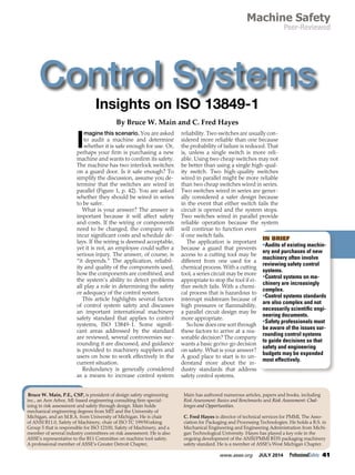
![42 ProfessionalSafety JULY 2014 www.asse.org
Machine Control
Safety Standards
Machine controls have
evolved from simple hardware
circuits to increasingly com-
plex hardware and software
systems. Although still used,
relays have been supplanted
by programmable logic con-
trollers (PLCs) and more re-
cently by safety-rated PLCs.
Control systems use increas-
ingly sophisticated complex
integrated circuits, micropro-
cessors and firmware. This
has enabled great advance-
ments in many respects, yet
has added complexity to con-
trol system designs. When
control systems fail to per-
form as expected, machines
can move unexpectedly or not
stop when expected, which can cause injuries or
damage equipment or products. The more complex
the systems, the greater the difficulty in identifying
and preventing unintended consequences.
Control system safety standards have also
evolved from EN 954-1 (1996) to the more recent
ISO 13849-1 (2006). The term control reliability has
been used in the U.S. for several years, but much
confusion remains regarding exactly what the term
means. As a result, the definition as it relates to a
specific control system is open to interpretation.
The term functional safety emerged as a result
of the effort to evaluate the safety-related perfor-
mance of control systems at the black box or func-
tional level. Functional safety formed the basis for
the standards that followed.
EN 954-1 (1996) and ISO 13849-1 (1999) intro-
duced categories (B, 1-4) that provide the structure
or architecture for control circuits. As the categories
increase, the required architecture also increases,
from single channel (a simple circuit) to monitor-
ing (such as an indicator light), redundancy (two
switches and/or two wires) and self-checking (active
testing to ensure operational). Figure 2 illustrates
the standard’s guidance on category selection.
The 2006 revision of ISO 13849-1 introduced a
probabilistic determination of potential control
system failures. The standard’s introduction in-
cludes the following:
The ability of safety-related parts of control sys-
tems to perform a safety function under foresee-
able conditions is allocated one of five levels,
called performance levels (PL). These perfor-
mance levels are defined in terms of probability of
dangerous failure per hour.
The standard uses PLs as the metric used to dis-
cuss control systems (Figure 3, p. 44).
Initially, the standard was published with great
expectations. Over the ensuing years, the effort to
introduce reliability calculations has met some re-
sistance in industry. Some are pushing to require
the PL methodology while
others are resisting that effort.
The primary concerns can be
summarized as follows: The
theory, although apparently
sound, does not work easily in
practice.
As described in EN 954-1
and ISO 13849-1 (1999), cat-
egories have been largely ad-
opted and used by machinery
suppliers worldwide. Most
machinery builders in the
global marketplace are famil-
iar with and use categories to
design control systems. How-
ever, even though a revised
version of ISO 13849-1 was
published in 2006, few ma-
chinery suppliers and users in
the U.S. are familiar with it.
While machines will increas-
ingly be built to this standard, it may take a decade
or more before this occurs in great numbers, in part
because of the complexity of control systems and of
the standard itself.
For SH&E professionals, understanding the
basics and central issues can inform negotiations
with suppliers and aid decision making that affects
safety and costs. The easy answer is, “We want the
best/safest for our employees.” Although an ad-
mirable sentiment, this is no smarter than walk-
ing into a car dealership and expressing the same
thought. You will likely drive out with the top-line
vehicle, a car loan, a service plan, an extended war-
ranty and other extras that have little to do with
your actual transportation needs.
In the past 2 years, three European companies
that supply machinery have budgeted €250,000,
€300,000 and €350,000 ($340,800, $409,000 and
$447,470, respectively) to confirm that their ma-
chinery designs met ISO 13849-1 requirements.
None changed their designs as a result of the analy-
ses. Perhaps these funds would have been better
spent to achieve actual safety improvements rathter
than simply documenting compliance to a standard.
As Manuele (2013) states:
Resources are always limited. Staffing and mon-
ey are never adequate to attend to all risks. The
greatest good to employees, employers and
society is attained if available resources are ef-
fectively and economically applied to avoid,
eliminate or control hazards and the risks that
derive from them. . . . [S]afety professionals must
be capable of distinguishing the more significant
from the lesser significant. (pp. 55-56)
Learning about ISO 13849-1 and control systems
can help safety professionals achieve this goal.
Overview of the 2006 Standard
The 1999 version of the standard provided the
architecture for control systems, but it lacked any
mechanism for verifying or validating that these
Figure 1
Simple Series &
Parallel Circuits](data:image/gif;base64,R0lGODlhAQABAIAAAAAAAP///yH5BAEAAAAALAAAAAABAAEAAAIBRAA7)