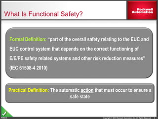
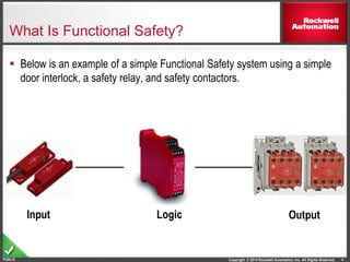
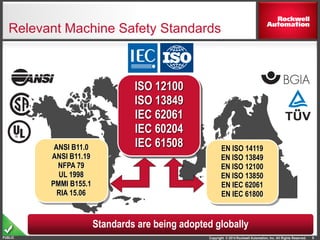
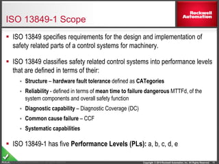
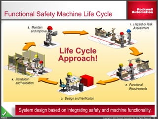
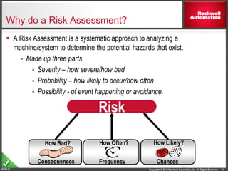
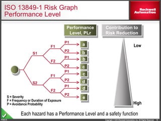
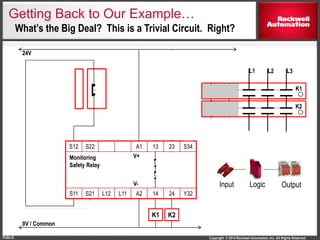
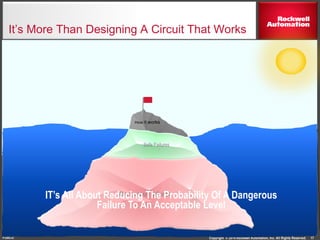
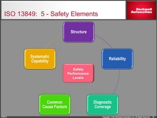
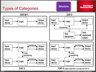
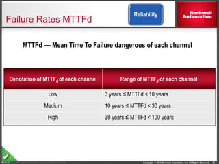
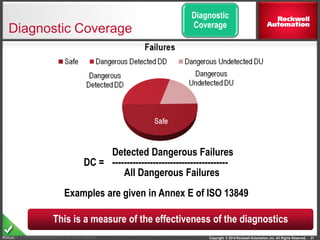
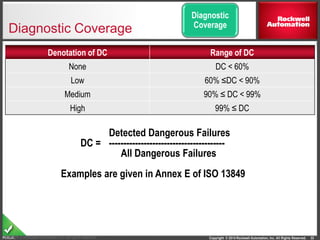
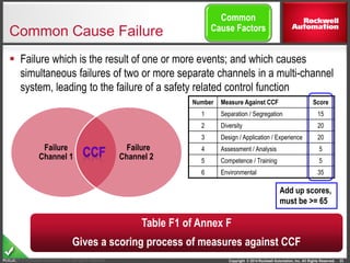
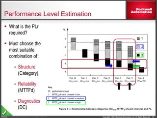
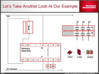
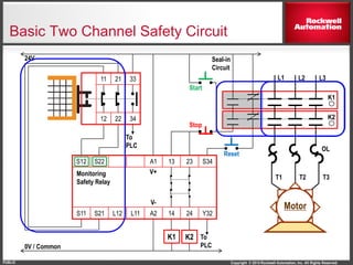
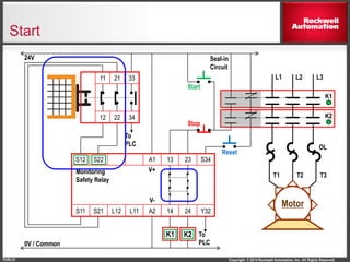
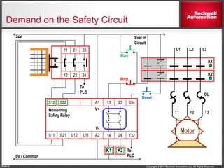
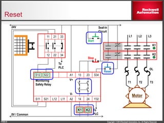
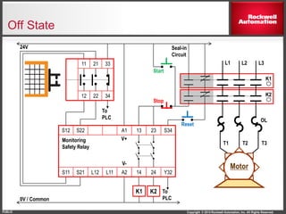
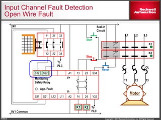
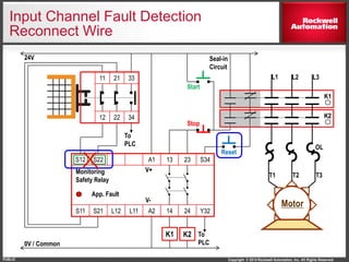
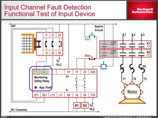
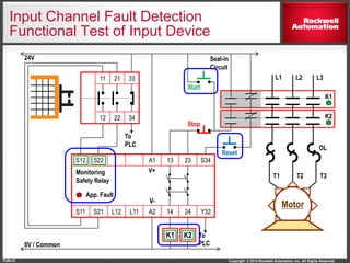
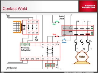
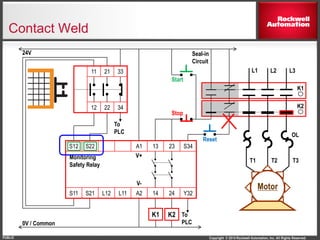
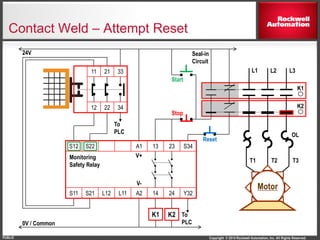
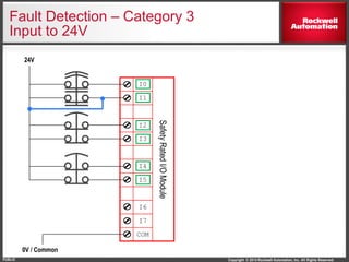
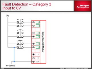
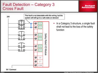
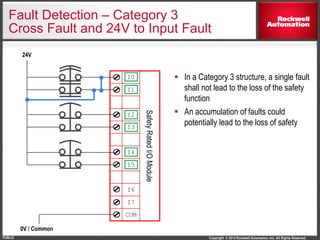
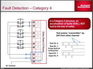
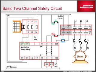
More Related Content
Similar to T89 introductiontofunctionalsafetyformachinery
Similar to T89 introductiontofunctionalsafetyformachinery (20)
More from Vo Quoc Hieu (8)
T89 introductiontofunctionalsafetyformachinery
- 1. Copyright © 2014 Rockwell Automation, Inc. All Rights
PUBLIC
PUBLIC - 5058-CO900GRev 5058-CO900E
PUBLIC INFORMATION
Introduction to Functional Safety for Machinery
Tim Roback
Marketing Manager, Safety Systems
- 2. Copyright © 2014 Rockwell Automation, Inc. All Rights Reserved.PUBLIC 2
Introduction To Functional Safety
Intro to Standards
We Have Tools
Functional Safety Defined
Example Safety Circuits
Terminology & Basic Concepts
- 3. Copyright © 2014 Rockwell Automation, Inc. All Rights Reserved.PUBLIC
What Is Functional Safety?
3
Formal Definition: “part of the overall safety relating to the EUC and
EUC control system that depends on the correct functioning of
E/E/PE safety related systems and other risk reduction measures”
(IEC 61508-4 2010)
Practical Definition: The automatic action that must occur to ensure a
safe state
- 4. Copyright © 2014 Rockwell Automation, Inc. All Rights Reserved.PUBLIC
What Is Functional Safety?
Below is an example of a simple Functional Safety system using a simple
door interlock, a safety relay, and safety contactors.
4
Input Logic Output
- 5. Copyright © 2014 Rockwell Automation, Inc. All Rights Reserved.PUBLIC
Are There Other Types of Safety?
5
Lock-Out-Tag-Out
Fixed or Hard Guarding
Sure
PPE
- 6. Copyright © 2014 Rockwell Automation, Inc. All Rights Reserved.PUBLIC
How Much Safety Do I Need
What do I do now?
Where do I begin?
6
Let’s Talk About Some Safety Standards…
- 7. Copyright © 2014 Rockwell Automation, Inc. All Rights Reserved.PUBLIC
Evolution of Functional Safety
Functional Safety Has Been Around For More Than 40 Years
7
Entertainment Industry
Early Functional Safety Pioneers
How Did They Do It?
Metal Forming Industry
Entertainment Industry
- 8. Copyright © 2014 Rockwell Automation, Inc. All Rights Reserved.PUBLIC
Not All Press Applications Were Pioneering…
8
- 9. Copyright © 2014 Rockwell Automation, Inc. All Rights Reserved.PUBLIC
ISO 13849
IEC 61508
Relevant Machine Safety Standards
9
ISO 12100
ISO 13849
IEC 62061
IEC 60204
IEC 61508 EN ISO 14119
EN ISO 13849
EN ISO 12100
EN ISO 13850
EN IEC 62061
EN IEC 61800
ANSI B11.0
ANSI B11.19
NFPA 79
UL 1998
PMMI B155.1
RIA 15.06
Standards are being adopted globally
- 10. Copyright © 2014 Rockwell Automation, Inc. All Rights Reserved.PUBLIC
Which One Is Right For My Needs?
10
ISO 13849
Machine Builders & End Users
Increasingly Focus On This One
IEC 61508
Rockwell Automation Needs To
Focus On This One
- 11. Copyright © 2014 Rockwell Automation, Inc. All Rights Reserved.PUBLIC
ISO 13849-1 Scope
ISO 13849 specifies requirements for the design and implementation of
safety related parts of a control systems for machinery.
ISO 13849 classifies safety related control systems into performance levels
that are defined in terms of their:
Structure – hardware fault tolerance defined as CATegories
Reliability - defined in terms of mean time to failure dangerous MTTFd, of the
system components and overall safety function
Diagnostic capability – Diagnostic Coverage (DC)
Common cause failure – CCF
Systematic capabilities
ISO 13849-1 has five Performance Levels (PLs): a, b, c, d, e
11Copyright © Rockwell Automation, Inc. All rights reserved.
- 12. Copyright © 2014 Rockwell Automation, Inc. All Rights Reserved.PUBLIC
What’s Next?
12
Regardless of what machine safety standard is
most appropriate for your customers or industry, it is
important to think about three things:
• Safety as a Lifecycle Process
• Risk Assessments
• Mitigation of Risk
- 13. Copyright © 2014 Rockwell Automation, Inc. All Rights Reserved.PUBLIC
Functional Safety Machine Life Cycle
13
Life Cycle
Approach!
5. Maintain
and Improve
1. Hazard or Risk
Assessment
4. Installation
and Validation 2. Functional
Requirements
3. Design and Verification
System design based on integrating safety and machine functionality.
- 14. Copyright © 2014 Rockwell Automation, Inc. All Rights Reserved.PUBLIC
Why do a Risk Assessment?
A Risk Assessment is a systematic approach to analyzing a
machine/system to determine the potential hazards that exist.
Made up three parts
Severity – how severe/how bad
Probability – how likely to occur/how often
Possibility - of event happening or avoidance.
TEXT
How Likely?
Chances
How Often?
Frequency
How Bad?
Consequences
Risk
14
- 15. Copyright © 2014 Rockwell Automation, Inc. All Rights Reserved.PUBLIC
ISO 13849-1 Risk Graph
Performance Level
Each hazard has a Performance Level and a safety function
S1
S2
F2
F1
Performance
Level, PLr
a
b
P1
P2
e
c
d
P1
P2
P1
P2
P1
P2
F2
F1
Contribution to
Risk Reduction
Low
High
S = Severity
F = Frequency or Duration of Exposure
P = Avoidance Probability
b
c
d
15
- 16. Copyright © 2014 Rockwell Automation, Inc. All Rights Reserved.PUBLIC
S12 S22 A1 13 23 S34
S11 S21 L12 L11 A2 14 24 Y32
K1
K1
L1 L2 L3
K2
24V
0V / Common
Monitoring
Safety Relay
Reset
Stop
Start
V+
V-
K2
Getting Back to Our Example…
OutputLogicInput
What’s the Big Deal? This is a Trivial Circuit. Right?
- 17. Copyright © 2014 Rockwell Automation, Inc. All Rights Reserved.PUBLIC
How it Fails
It’s More Than Designing A Circuit That Works
17
How it works
How it FailsResidual Dangerous Failures
Safe Failures
Dangerous failuresIT’s All About Reducing The Probability Of A Dangerous
Failure To An Acceptable Level
- 18. Copyright © 2014 Rockwell Automation, Inc. All Rights Reserved.PUBLIC
ISO 13849: 5 - Safety Elements
18
Structure
Reliability
Diagnostic
Coverage
Common
Cause Factors
Systematic
Capability
- 19. Copyright © 2014 Rockwell Automation, Inc. All Rights Reserved.PUBLIC
Types of Categories
CAT B/1 CAT 2
CAT 3 CAT 4 (higher diagnostic coverage that CAT 3)
Input
device
Logic
Output
device
monitoring
Test
equipment
Test
equipment
output
Input
device
Logic
Output
device
Input
device
Logic
Output
device
monitoring
Input
device
Logic
Output
device
monitoring
cross
monitoring
Input
device
Logic
Output
device
monitoring
Input
device
Logic
Output
device
monitoring
cross
monitoring
Structure
- 20. Copyright © 2014 Rockwell Automation, Inc. All Rights Reserved.PUBLIC
Failure Rates MTTFd
Denotation of MTTFd of each channel Range of MTTFd of each channel
Low 3 years ≤ MTTFd < 10 years
Medium 10 years ≤ MTTFd < 30 years
High 30 years ≤ MTTFd < 100 years
20Copyright © Rockwell Automation, Inc. All rights reserved.
MTTFd –– Mean Time To Failure dangerous of each channel
Reliability
- 21. Copyright © 2014 Rockwell Automation, Inc. All Rights Reserved.PUBLIC
Diagnostic Coverage
21Copyright © Rockwell Automation, Inc. All rights reserved.
Detected Dangerous Failures
DC = ----------------------------------------
All Dangerous Failures
Examples are given in Annex E of ISO 13849
This is a measure of the effectiveness of the diagnostics
Diagnostic
Coverage
- 22. Copyright © 2014 Rockwell Automation, Inc. All Rights Reserved.PUBLIC
Diagnostic Coverage
Denotation of DC Range of DC
None DC < 60%
Low 60% ≤DC < 90%
Medium 90% ≤ DC < 99%
High 99% ≤ DC
22Copyright © Rockwell Automation, Inc. All rights reserved.
Detected Dangerous Failures
DC = ----------------------------------------
All Dangerous Failures
Examples are given in Annex E of ISO 13849
Diagnostic
Coverage
- 23. Copyright © 2014 Rockwell Automation, Inc. All Rights Reserved.PUBLIC
Common Cause Failure
Failure which is the result of one or more events; and which causes
simultaneous failures of two or more separate channels in a multi-channel
system, leading to the failure of a safety related control function
23Copyright © Rockwell Automation, Inc. All rights reserved.
Failure
Channel 1
Failure
Channel 2
Number Measure Against CCF Score
1 Separation / Segregation 15
2 Diversity 20
3 Design / Application / Experience 20
4 Assessment / Analysis 5
5 Competence / Training 5
6 Environmental 35
Add up scores,
must be >= 65
Table F1 of Annex F
Gives a scoring process of measures against CCF
Common
Cause Factors
- 24. Copyright © 2014 Rockwell Automation, Inc. All Rights Reserved.PUBLIC
Performance Level Estimation
What is the PLr
required?
Must choose the
most suitable
combination of :
Structure
(Category),
Reliability
(MTTFd)
Diagnostics
(DC)
24Copyright © Rockwell Automation, Inc. All rights reserved.
- 25. Copyright © 2014 Rockwell Automation, Inc. All Rights Reserved.PUBLIC
Confused Yet?
How Do I Figure Out:
Component reliability?
Diagnostic coverage?
Common Cause Factors?
How do I know whether or not systematic
capability was used to design these devices?
Don’t Panic. There’s good news!
25
Much Of The Complexity, Calculations and Confusion Can Be
Avoided Through The Use Of Safety Rated Devices
- 26. Copyright © 2014 Rockwell Automation, Inc. All Rights Reserved.PUBLIC
Safety Rated Devices Simplify The
Process
Complex devices such as safety PLC’s, Safety I/O, Safety Switches and
even safety relays come with a safety rating
“This devices is suitable for applications up to and including PLe when
used in accordance with the application guidelines”
Additionally safety calculators help determine the safety integrity level of a
function using safety rated devices .
26
Even With Safety Rated Devices, the Machine Builder
is Still on the hook to ensure a compliant safety function
- 27. Copyright © 2014 Rockwell Automation, Inc. All Rights Reserved.PUBLIC
S12 S22 A1 13 23 S34
S11 S21 L12 L11 A2 14 24 Y32
K1
K1
L1 L2 L3
K2
24V
0V / Common
Monitoring
Safety Relay
Reset
Stop
Start
V+
V-
K2
Let’s Take Another Look At Our Example
OutputLogicInput
- 28. Copyright © 2014 Rockwell Automation, Inc. All Rights Reserved.PUBLIC
S12 S22 A1 13 23 S34
S11 S21 L12 L11 A2 14 24 Y32
11 21 33
12 22 34
K1
Motor
T3T2T1
K1
OL
L1 L2 L3
K2
24V
0V / Common
Monitoring
Safety Relay
Reset
Stop
Start
Seal-in
Circuit
V+
V-
To
PLC
To
PLC
K2
Basic Two Channel Safety Circuit
- 29. Copyright © 2014 Rockwell Automation, Inc. All Rights Reserved.PUBLIC
S12 S22 A1 13 23 S34
S11 S21 L12 L11 A2 14 24 Y32
11 21 33
12 22 34
K1
Motor
T3T2T1
K1
OL
L1 L2 L3
K2
24V
0V / Common
Monitoring
Safety Relay
Reset
Stop
Start
Seal-in
Circuit
V+
V-
To
PLC
To
PLC
K2
Start
- 30. Copyright © 2014 Rockwell Automation, Inc. All Rights Reserved.PUBLIC
S12 S22 A1 13 23 S34
S11 S21 L12 L11 A2 14 24 Y32
11 21 33
12 22 34
K1
Motor
T3T2T1
K1
OL
L1 L2 L3
K2
24V
0V / Common
Monitoring
Safety Relay
Reset
Stop
Start
Seal-in
Circuit
V+
V-
To
PLC
To
PLC
K2
Demand on the Safety Circuit
- 31. Copyright © 2014 Rockwell Automation, Inc. All Rights Reserved.PUBLIC
S12 S22 A1 13 23 S34
S11 S21 L12 L11 A2 14 24 Y32
11 21 33
12 22 34
K1
Motor
T3T2T1
K1
OL
L1 L2 L3
K2
24V
0V / Common
Monitoring
Safety Relay
Reset
Stop
Start
Seal-in
Circuit
V+
V-
To
PLC
To
PLC
K2
Reset
- 32. Copyright © 2014 Rockwell Automation, Inc. All Rights Reserved.PUBLIC
S12 S22 A1 13 23 S34
S11 S21 L12 L11 A2 14 24 Y32
11 21 33
12 22 34
K1
Motor
T3T2T1
K1
OL
L1 L2 L3
K2
24V
0V / Common
Monitoring
Safety Relay
Reset
Stop
Start
Seal-in
Circuit
V+
V-
To
PLC
To
PLC
K2
Off State
- 33. Copyright © 2014 Rockwell Automation, Inc. All Rights Reserved.PUBLIC
Input Channel Fault Detection
34
- 34. Copyright © 2014 Rockwell Automation, Inc. All Rights Reserved.PUBLIC
S12 S22 A1 13 23 S34
S11 S21 L12 L11 A2 14 24 Y32
11 21 33
12 22 34
K1
Motor
T3T2T1
K1
OL
L1 L2 L3
K2
24V
0V / Common
Monitoring
Safety Relay
Reset
Stop
Start
Seal-in
Circuit
V+
V-
To
PLC
To
PLC
K2
Input Channel Fault Detection
Open Wire Fault
App. Fault
- 35. Copyright © 2014 Rockwell Automation, Inc. All Rights Reserved.PUBLIC
S12 S22 A1 13 23 S34
S11 S21 L12 L11 A2 14 24 Y32
11 21 33
12 22 34
K1
Motor
T3T2T1
OL
L1 L2 L3
K2
24V
0V / Common
Monitoring
Safety Relay
Stop
Start
Seal-in
Circuit
V+
V-
To
PLC
To
PLC
Input Channel Fault Detection
Reconnect Wire
App. Fault
K1
K2
Reset
- 36. Copyright © 2014 Rockwell Automation, Inc. All Rights Reserved.PUBLIC
S12 S22 A1 13 23 S34
S11 S21 L12 L11 A2 14 24 Y32
11 21 33
12 22 34
K1
Motor
T3T2T1
OL
L1 L2 L3
K2
24V
0V / Common
Monitoring
Safety Relay
Reset
Stop
Start
Seal-in
Circuit
V+
V-
To
PLC
To
PLC
Input Channel Fault Detection
Functional Test of Input Device
App. Fault
K1
K2
- 37. Copyright © 2014 Rockwell Automation, Inc. All Rights Reserved.PUBLIC
S12 S22 A1 13 23 S34
S11 S21 L12 L11 A2 14 24 Y32
11 21 33
12 22 34
K1
Motor
T3T2T1
K1
OL
L1 L2 L3
K2
24V
0V / Common
Monitoring
Safety Relay
Reset
Stop
Start
Seal-in
Circuit
V+
V-
To
PLC
To
PLC
K2
Input Channel Fault Detection
Functional Test of Input Device
App. Fault
- 38. Copyright © 2014 Rockwell Automation, Inc. All Rights Reserved.PUBLIC
Contact Weld
40
- 39. Copyright © 2014 Rockwell Automation, Inc. All Rights Reserved.PUBLIC
S12 S22 A1 13 23 S34
S11 S21 L12 L11 A2 14 24 Y32
11 21 33
12 22 34
K1
Motor
T3T2T1
K1
OL
L1 L2 L3
K2
24V
0V / Common
Monitoring
Safety Relay
Reset
Stop
Start
Seal-in
Circuit
V+
V-
To
PLC
To
PLC
K2
Contact Weld
- 40. Copyright © 2014 Rockwell Automation, Inc. All Rights Reserved.PUBLIC
S12 S22 A1 13 23 S34
S11 S21 L12 L11 A2 14 24 Y32
11 21 33
12 22 34
K1
Motor
T3T2T1
K1
OL
L1 L2 L3
K2
24V
0V / Common
Monitoring
Safety Relay
Reset
Stop
Start
Seal-in
Circuit
V+
V-
To
PLC
To
PLC
K2
Contact Weld
- 41. Copyright © 2014 Rockwell Automation, Inc. All Rights Reserved.PUBLIC
S12 S22 A1 13 23 S34
S11 S21 L12 L11 A2 14 24 Y32
11 21 33
12 22 34
K1
Motor
T3T2T1
K1
OL
L1 L2 L3
K2
24V
0V / Common
Monitoring
Safety Relay
Reset
Stop
Start
Seal-in
Circuit
V+
V-
To
PLC
To
PLC
K2
Contact Weld – Attempt Reset
- 42. Copyright © 2014 Rockwell Automation, Inc. All Rights Reserved.PUBLIC
Fault Detection – Category 3
Input to 24V
I0
SafetyRatedI/OModule
I1
I2
I3
I4
I5
I6
I7
COM
24V
0V / Common
- 43. Copyright © 2014 Rockwell Automation, Inc. All Rights Reserved.PUBLIC
Fault Detection – Category 3
Open Wire
I0
SafetyRatedI/OModule
I1
I2
I3
I4
I5
I6
I7
COM
24V
0V / Common
- 44. Copyright © 2014 Rockwell Automation, Inc. All Rights Reserved.PUBLIC
Fault Detection – Category 3
Input to 0V
I0
SafetyRatedI/OModule
I1
I2
I3
I4
I5
I6
I7
COM
24V
0V / Common
- 45. Copyright © 2014 Rockwell Automation, Inc. All Rights Reserved.PUBLIC
Fault Detection – Category 3
Cross Fault
In a Category 3 structure, a single fault
shall not lead to the loss of the safety
function
I0
SafetyRatedI/OModule
I1
I2
I3
I4
I5
I6
I7
COM
24V
0V / Common
This fault is not detectable with this wiring, but the
system will still go to a safe state on demand
- 46. Copyright © 2014 Rockwell Automation, Inc. All Rights Reserved.PUBLIC
Fault Detection – Category 3
Cross Fault and 24V to Input Fault
In a Category 3 structure, a single fault
shall not lead to the loss of the safety
function
An accumulation of faults could
potentially lead to the loss of safety
I0
SafetyRatedI/OModule
I1
I2
I3
I4
I5
I6
I7
COM
24V
0V / Common
- 47. Copyright © 2014 Rockwell Automation, Inc. All Rights Reserved.PUBLIC
Fault Detection – Category 4
I0
SafetyRatedI/OModule
I1
I2
I3
I4
I5
T0
T1
COM
0V / Common
In a Category 4 structure, an
accumulation of faults SHALL NOT
lead to the loss of safety
Test pulses “overwritten” by
24V from other channel
Input Ch. 1
Test Ch. 0
Test Ch. 1
Cross fault at
vertical line
Input Ch. 0
- 48. Copyright © 2014 Rockwell Automation, Inc. All Rights Reserved.PUBLIC
S12 S22 A1 13 23 S34
S11 S21 L12 L11 A2 14 24 Y32
11 21 33
12 22 34
K1
Motor
T3T2T1
K1
OL
L1 L2 L3
K2
24V
0V / Common
Monitoring
Safety Relay
Reset
Stop
Start
Seal-in
Circuit
V+
V-
To
PLC
To
PLC
K2
Basic Two Channel Safety Circuit
- 49. Copyright © 2014 Rockwell Automation, Inc. All Rights Reserved.PUBLIC
Ok, Maybe This Isn’t So Hard
However, The Machine Builder still has to ensure the performance level of
the safety function meets the performance level required.
Question: If I use all safety devices rated for applications up to PLe, will my
safety function achieve PLe?
Answer: It depends. The structure you choose will affect the performance
level of the safety function. Also, not all safety rated devices consume the
same portion of the overall safety budget.
The math required to calculate all of the performance information can get
complicated. We Have Tools To Help With This As Well
53
- 50. Copyright © 2014 Rockwell Automation, Inc. All Rights Reserved.PUBLIC
SISTEMA Tool
What is SISTEMA and its role?
SISTEMA – Safety Integrity Software Tool for the Evaluation of
Machine Applications
The SISTEMA software utility provides designers, developers and
testers of safety-related machine controls with comprehensive support
in the evaluation of SRP/CS in the context of ISO 13849-1.
The tool enables designers to model the structure of the safety-related
control components based upon the designated architectures.
SISTEMA is a free software tool designed by Germany’s IFA (Institute
for Occupational Safety & Health).
The tool offers automated calculation of a safety function’s attained PL
by using product data provided by safety product manufacturer.
54
- 51. Copyright © 2014 Rockwell Automation, Inc. All Rights Reserved.PUBLIC 55
Safety Functions
Safety Function: Emergency Stop
Products: Light Curtain / GuardLogix
Safety Rating: PLe, Cat. 4 to EN ISO 13849.1 2008
Provides Everything Needed to
Design, Document & Implement
Common Safety Functions
• Safety Requirements Specification (SRS)
• BOM
• Schematics
• Sample Code
• Safety Calculations
• Verification & Validations Plans
- 52. Copyright © 2014 Rockwell Automation, Inc. All Rights Reserved.PUBLIC
Common Safety Functions Library
Safety Functions documents include Safety relay solutions, configurable
relay solutions and GuardLogix solutions.
A wide variety of safety Functions are available; For example
E-stop
Light Curtains
Two hand control
Enabling Switch
Guard-locking switches
Door interlocks
& More
56
- 53. Copyright © 2014 Rockwell Automation, Inc. All Rights Reserved.
PUBLIC
PUBLIC - 5058-CO900G
.
Connect with us.
www.rockwellautomation.com
Copyright © 2013 Rockwell Automation, Inc. All Rights Reserved.
www.rockwellautomation.com
Follow ROKAutomation on Facebook & Twitter.
Connect with us on LinkedIn.
Rev 5058-CO900E
PUBLIC INFORMATION
Questions?
57