Microcontroller based Integrated Circuit Tester

The digital integrated circuit (IC) tester is implemented by using the ATmega32 microcontroller . The microcontroller processes the inputs and outputs and displays the results on a Liquid Crystal Display (LCD). The basic function of the digital IC tester is to test a digital IC for correct logical functioning as described in the truth table and/or function table. The designed model can test digital ICs having 14 pins. Since it is programmable, any number of ICs can be tested . This model applies the necessary signals to the inputs of the IC, monitoring the outputs at each stage and comparing them with the outputs in the truth table. Any discrepancy in the functioning of the IC results in a fail indication, displays the faulty and good gates on the LCD. The testing procedure is accomplished with the help of keypad keys present on the main board design. The test has been accomplished with most commonly used digital IC's, mainly belonging to the 74 series. Digital IC tester tests three samples of IC's ( NAND, NOT, NOR). The design is flexible . We can add extra IC bases and subroutines to test any other IC in the 74 series.

Recommended
More Related Content
What's hot
What's hot (20)
Viewers also liked
Viewers also liked (11)
Similar to Microcontroller based Integrated Circuit Tester
Similar to Microcontroller based Integrated Circuit Tester (20)
Recently uploaded
Recently uploaded (20)
Microcontroller based Integrated Circuit Tester
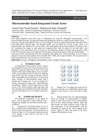
- 1. Yousif Taha Yousif Elamin Int. Journal of Engineering Research and Applications www.ijera.com ISSN : 2248-9622, Vol. 5, Issue 2, ( Part -2) February 2015, pp.118-122 www.ijera.com 118 | P a g e Microcontroller based Integrated Circuit Tester Yousif Taha Yousif Elamin1 , Abdelrasoul Jabar Alzubaidi2 1 Electronics Dept. - Faculty of Engineering & Technology - University of Gezira. 2 Electronics Dept. - Engineering College – Sudan University of science and Technology Abstract The digital integrated circuit (IC) tester is implemented by using the ATmega32 microcontroller . The microcontroller processes the inputs and outputs and displays the results on a Liquid Crystal Display (LCD). The basic function of the digital IC tester is to test a digital IC for correct logical functioning as described in the truth table and/or function table. The designed model can test digital ICs having 14 pins. Since it is programmable, any number of ICs can be tested . This model applies the necessary signals to the inputs of the IC, monitoring the outputs at each stage and comparing them with the outputs in the truth table. Any discrepancy in the functioning of the IC results in a fail indication, displays the faulty and good gates on the LCD. The testing procedure is accomplished with the help of keypad keys present on the main board design. The test has been accomplished with most commonly used digital IC's, mainly belonging to the 74 series. Digital IC tester tests three samples of IC's ( NAND, NOT, NOR). The design is flexible . We can add extra IC bases and subroutines to test any other IC in the 74 series. Keywords : IC tester , ATmega32 , microcontroller , LCD , , keypad , 74 series , gates I. INTRODUCTION An Integrated Circuit tester (IC tester) is used to test Integrated Circuits (ICs). We can easily test any digital IC using this kind of an IC tester. The circuit design is made more reliable and easy since we don’t need to rig up different kind of circuits for different kind of ICs, each time we need to test them .This IC tester is affordable and user-friendly. It is constructed using ATmega 32 microcontroller along with a keypad and a display unit. It can test digital ICs having a maximum of 14 pins. By a simple hardware and software addition , this IC tester can test a wide variety of ICs which includes simple logic gates and also sequential and combinational ICs like flip-flops, counters, shift registers etc. It is portable and easy to use. II. HARDWARE DESIGN The Hardware components of the digital IC tester can be discussed in three different units - Keypad unit, Display unit and Microcontroller unit - as follows : i) Keypad Unit: The keypad makes use of a 4 line - 3 column matrix keyboard and is connected to port D of the microcontroller. The key positions are shown in Figure (1). The principle of detecting a key is by getting a logic value on the pin of the microcontroller . Figure (1) keypad unit ii) Display Unit: To display the result and for interaction with the user an HD44780 Liquid Crystal Display is used. This is a 2 line LCD with 16 input pins. ii) Microcontroller Unit: For implementing this device an ATmega 32 microcontroller of ATMEL family is used. Since port D of the microcontroller does not have default pull-up resistors, eight 10K ohm resisters are used to pull-up 8 pins of port D. The connections of the microcontroller with the peripherals are shown in the block diagram of the system. Figure (2) shows the layout of the block diagram of the hardware circuit. REVIEW ARTICLE OPEN ACCESS
- 2. Yousif Taha Yousif Elamin Int. Journal of Engineering Research and Applications www.ijera.com ISSN : 2248-9622, Vol. 5, Issue 2, ( Part -2) February 2015, pp.118-122 www.ijera.com 119 | P a g e Figure (2) block diagram of the hardware circuit. To test a particular digital IC, one needs to insert the IC into the IC socket and enter the IC number using the keypad and then processing starts. The IC number gets displayed in the LCD display unit. III. APPROACH The design is for conducting quality control test of the integrated circuits for the normal operation .This process includes a verification of the truth table of the gates in the integrated circuit. The steps for conducting the verification test for a two inputs gate is described as follows: Step1 :Feeding the 2 inputs gate with the first values in the truth table (00)2 . Step2 :Checking the output value . Step3 : Ensuring that the output corresponds to the input values in the truth table are correct. Steps (1,2 &3) should be repeated for the other binary input values in the truth table . Now if all the possible input values in the truth table give correct binary output value , we proceed to test the other gates in the integrated circuit. If all the gates build in the integrated circuit give correct results corresponding to the truth table , then the integrated circuit pass the test. Any malfunction of one gate or more in the integrated circuit gives it fail in the test. The failed integrated circuit is considered unserviceable. The integrated circuits subjected to quality control test are the universal gates and the inverter as follows: (1) The (SN7400) , It includes quad two inputs NAND gates. Figure (3) shows the gate and the truth table of the gate .Equation (1) gives the Boolean function of the gate. F = A . B …………………………………(1)
- 3. Yousif Taha Yousif Elamin Int. Journal of Engineering Research and Applications www.ijera.com ISSN : 2248-9622, Vol. 5, Issue 2, ( Part -2) February 2015, pp.118-122 www.ijera.com 120 | P a g e Figure (3) Two inputs NAND gate with Truth Table (2) The (SN7402) , It includes quad two inputs NOR gates. Figure (4) shows the gate and the truth table of the gate. Equation (2) gives the Boolean function of the gate. F = A + B ……………………………(2) Figure (4 )Two inputs NOR gate with Truth Table (3) The (SN7404) : It includes hex inverter (NOT) gates. Figure (5) shows the gate and the truth table of the gate. Equation (3) gives the Boolean function of the gate . F = A …………………………..(3) Figure (5 ) NOT gate with Truth Table
- 4. Yousif Taha Yousif Elamin Int. Journal of Engineering Research and Applications www.ijera.com ISSN : 2248-9622, Vol. 5, Issue 2, ( Part -2) February 2015, pp.118-122 www.ijera.com 121 | P a g e IV. ALGORITHM The microcontroller algorithm includes a sequence of steps for the operation of the integrated circuit tester .The program in this design will be prepared by Bacom language and downloaded in the microcontroller by Pony Prog program in (.Hex) format. A PC is used for the Bascom program development and for downloading the (.Hex) file into the microcontroller .Figure (6) shows the interconnection between the PC and the microcontroller for programming and downloading operations. Figure (6) Connection for programming the microcontroller The algorithm for integrated circuit test includes the main program and three subroutines .One subroutine is written for conducting quality control test of each integrated circuit under test .The final quality control test result appears on the LCD .The algorithm is : Start Initialization: … Program (PORT A) of the microcontroller as output. … Clear (PORT A) output. … Program (PORT B) of the microcontroller as input. … Program (PORT C) of the microcontroller to interface with the LCD. … Program (PORT D) of the microcontroller as input. … Display (WELCOM) on the screen of the LCD. … if (keypad = 1) , then go to test of SN7400 … if (keypad = 2) , then go to test of SN7402 … if (keypad = 3) , then go to test of SN7404 Test of SN7400 : … For I = 1 to 4 … Initialize the gate. … Call quality control test of SN7400 subroutine. … Next Test SN7402: … For I = 1 to 4 … Initialize the gate. … Call quality control test of SN7402 subroutine. … Next Test SN7404: … For I = 1 to 6 … Initialize the gate. … Call quality control test of SN7404 subroutine. … Next End Quality control test of SN7400: … Display (SN7400) on the screen of the LCD. … Enter (00)2 to the input of the first NAND gate. … If (output = 1) , then go to second input value in the truth table. … Go to TEST FAIL display. Second input: … Enter (01)2 to the input of the first NAND gate. … If (output = 1) , then go to third input value in the truth table. … Go to TEST FAIL display. Third input: … Enter (10)2 to the input of the first NAND gate. … If (output = 1) , then go to fourth input value in the truth table. … Go to TEST FAIL display. Fourth input: … Enter (11)2 to the input of the first NAND gate. … If (output = 0) , then go to TEST PASS display.. … Go to TEST FAIL display. TEST FAIL display: … Display IC (SN7400) is FAULTY. … Go to Return. TEST PASS display: … Display IC (SN7400) is PASS. Return Quality control test of SN7402: … Display (SN7402) on the screen of the LCD. … Enter (00)2 to the input of the first NOR gate. … If (output = 1) , then go to second input value in the truth table. … Go to TEST FAIL display. Second input: … Enter (01)2 to the input of the first NOR gate. … If (output = 0) , then go to third input value in the truth table. … Go to TEST FAIL display.
- 5. Yousif Taha Yousif Elamin Int. Journal of Engineering Research and Applications www.ijera.com ISSN : 2248-9622, Vol. 5, Issue 2, ( Part -2) February 2015, pp.118-122 www.ijera.com 122 | P a g e Third input: … Enter (10)2 to the input of the first NOR gate. … If (output = 0) , then go to fourth input value in the truth table. … Go to TEST FAIL display. Fourth input: … Enter (11)2 to the input of the first NAND gate. … If (output = 0) , then go to TEST PAS display.. … Go to TEST FAIL display. TEST FAIL display: … Display IC (SN7402) is FAULTY. … Go to Return. TEST PASS display: … Display IC (SN7402) is PASS. Return Quality control test of SN7404: … Display (SN7404) on the screen of the LCD. … Enter (0)2 to the input of the first NOT gate. … If (output = 1) , then go to second input value in the truth table. … Go to TEST FAIL display. Second input: … Enter (1)2 to the input of the first NOT gate. … If (output = 0) , then go to TEST PASS display.. TEST FAIL display: … Display IC (SN7404) is FAULTY. … Go to Return. TEST PASS display: … Display IC (SN7404) is PASS. Return V. RESULTS The results obtained from testing a number of integrated circuits of three categories indicates their status and serviceability. Table (1) below shows the results of some samples of integrated circuits subjected to test . Table (1) the results of test some samples of integrated circuits . IC part number Number of IC’s under test Quality control test result SN7400 10 PASS SN7402 10 9 PASS, 1 FAIL SN7404 10 PASS VI. CONCLUSION It is essential to conduct the quality control tests for different samples of the integrated circuits in order to ensure its serviceability . The pass and fail results for the integrated circuits tests can be stored in a data base along with their source of supply. These results help in importing better quality IC’s from suppliers. REFERANCES [1] ABI Electronics. (2012, September 21). IC Tester Manufacturers. Available: www.abielectronics.com [2] Farr, J. (2008). Digital IC Tester. Wimborne Publishing Ltd, 61(4), 65-71. [3] Raina, S. et al.( 2009). Digital IC Tester. IEEE Journal, 22(7), 23-30. [4] RS Philippines. (2012, August 23). IC Tester. Available: www.rsphilippines.com. [5] West, G. L. et al. (1980). A Microcomputer-Controlled Testing System for Digital Integrated Circuits. IEEE [6] Yater, J. et al. (2012). First-ever High- Performance, Low-Power 32-bit Microcontrollers with Embedded Nanocrystal Flash and Enhanced EEPROM Memories. IEEE Journal, 22(13)