Downloaded 80 times


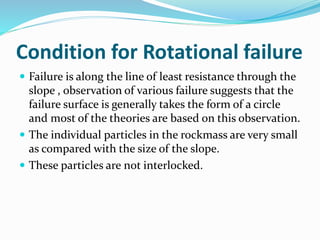

![Overturning moment = R W
i=1
n
i i sin
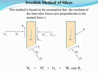
Restoring moment = R T
i=1
n
i
F
sisting Moment
Overturning Moment
c l N
W
i i i i
i
n
i i
i
n
Re
[ tan ]
sin
1
1
Case of drained slope is considered so Ui = 0](https://image.slidesharecdn.com/rotationalfailureanalysis-140420071347-phpapp02/85/Rotational-failure-analysis-20-320.jpg)
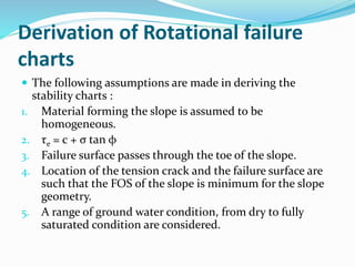
![F =
[ c l + (W - U )
W
i=1
n
i i i i i i
i=1
n
i i
cos tan ]
sin
F =
[ c l + W t
W
i=1
n
ui i i i ui
i=1
n
i i
cos an ]
sin
For effective stress analysis
For total stress (undrained) analysis](https://image.slidesharecdn.com/rotationalfailureanalysis-140420071347-phpapp02/85/Rotational-failure-analysis-22-320.jpg)
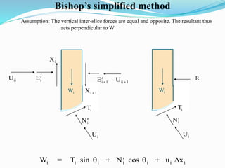
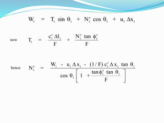
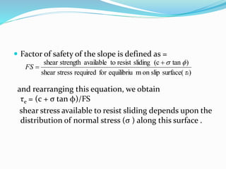
![Substitution of the expression for N’ into the equation for the factor of safety
F
sisting Moment
Overturning Moment
c l N
W
i i i i
i
n
i i
i
n
Re
[ tan ]
sin
1
1
leads to
F =
( c x + ( W - u x ) )
1
M ( )
W
i=1
n
i i i i i i
i
i=1
n
i i
tan
sin
where
M ( ) = [ 1 +
F
]i i i
i
cos tan
tan ](https://image.slidesharecdn.com/rotationalfailureanalysis-140420071347-phpapp02/85/Rotational-failure-analysis-30-320.jpg)
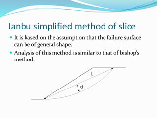
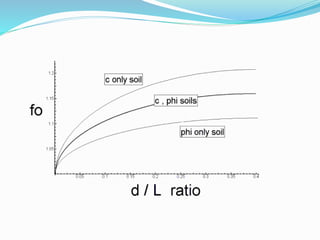
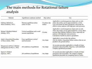


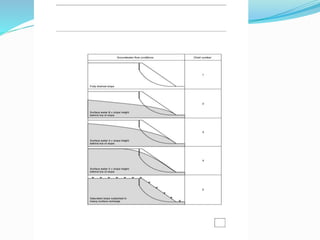
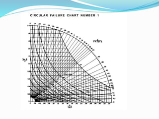
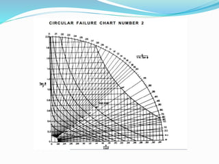
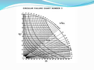
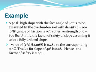
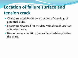
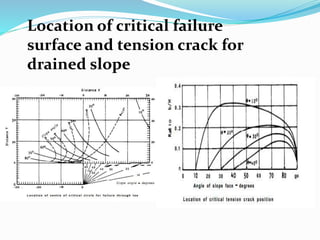
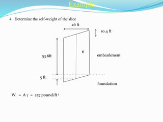
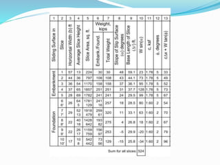
1. Rotational slope failures occur along a circular surface and theories are based on particles in rockmasses being small and not interlocked. 2. Stability charts are derived using assumptions like homogeneous material, shear strength equations, and failure surfaces passing through the slope toe. 3. Factor of safety is defined as the ratio of shear strength available to resist sliding to the shear stress required for equilibrium. Charts are used to locate failure surfaces and tension cracks for different groundwater conditions.

![Geotechnical Engineering-I [Lec #17: Consolidation]](https://cdn.slidesharecdn.com/ss_thumbnails/17-180924140731-thumbnail.jpg?width=640&height=640&fit=bounds)
![Geotechnical Engineering-I [Lec #19: Consolidation-III]](https://cdn.slidesharecdn.com/ss_thumbnails/19-180924141035-thumbnail.jpg?width=640&height=640&fit=bounds)
![Geotechnical Engineering-II [Lec #15 & 16: Schmertmann Method]](https://cdn.slidesharecdn.com/ss_thumbnails/15-181020124920-thumbnail.jpg?width=640&height=640&fit=bounds)


![Geotechnical Engineering-II [Lec #11: Settlement Computation]](https://cdn.slidesharecdn.com/ss_thumbnails/11-181020124840-thumbnail.jpg?width=640&height=640&fit=bounds)


![Geotechnical Engineering-I [Lec #21: Consolidation Problems]](https://cdn.slidesharecdn.com/ss_thumbnails/21-180924141121-thumbnail.jpg?width=640&height=640&fit=bounds)


![Geotechnical Engineering-II [Lec #13: Elastic Settlements]](https://cdn.slidesharecdn.com/ss_thumbnails/13-181020124852-thumbnail.jpg?width=640&height=640&fit=bounds)


![Geotechnical Engineering-II [Lec #4: Unconfined Compression Test]](https://cdn.slidesharecdn.com/ss_thumbnails/4-180930132645-thumbnail.jpg?width=640&height=640&fit=bounds)


![Geotechnical Engineering-II [Lec #28: Finite Slope Stability Analysis]](https://cdn.slidesharecdn.com/ss_thumbnails/28-181125070402-thumbnail.jpg?width=640&height=640&fit=bounds)


