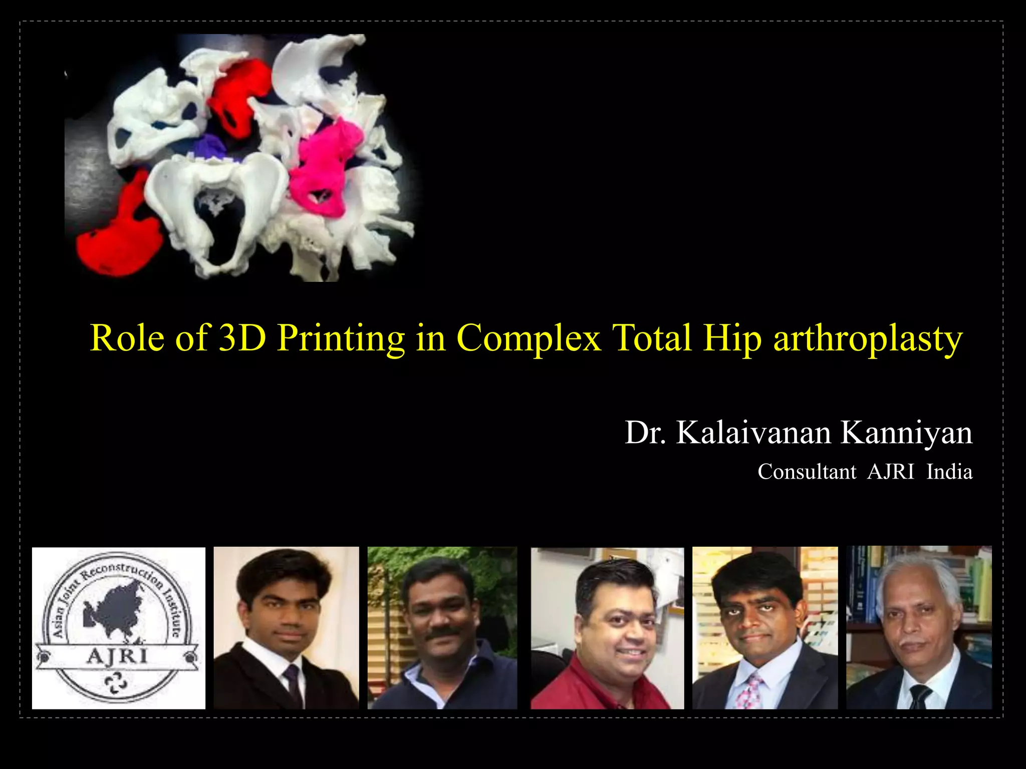
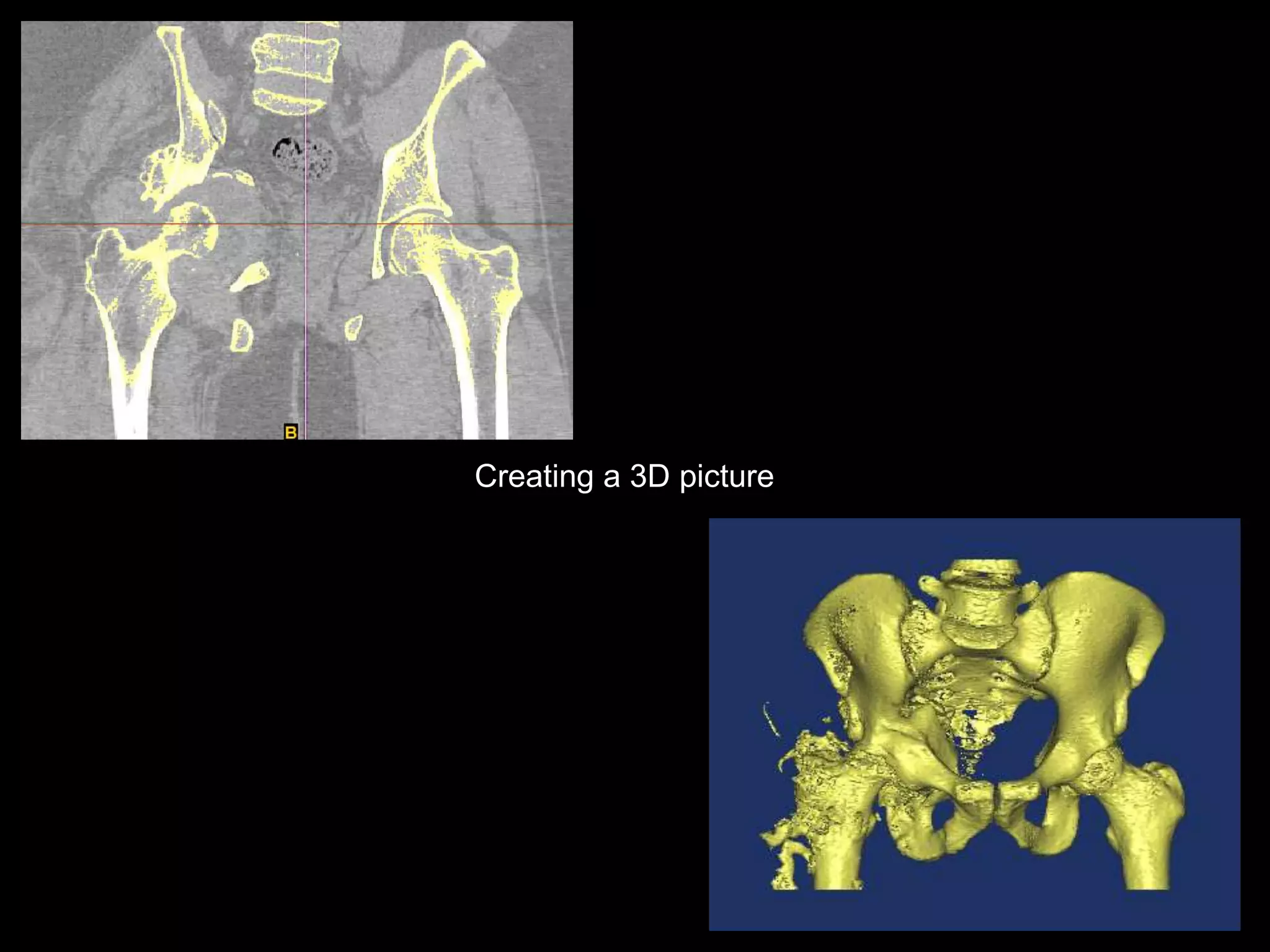
Role of 3D Printing in Complex Total Hip arthroplasty
Dr. Kalaivanan Kanniyan
Consultant AJRI India
Transformational technology
Rapid prototyping at your
fingertips
Tabletop revolution
Preparedness
Preparation
Precision
Less surprise
Pre operative drill
Pre operative replication of
whole process
Identification of bony landmark
ROLE of 3Dprinting &3DModel
HISTORY:
3D Printing @ Additive Manufacturing, AM
Process of creating a three dimensional object using additive manufacturing file (AFM),
in which the 3D object of any shape out of any material is made layer by layer
under computer control .
1980 First stage
1981 Hideo Kodama , Nagoya Municipal Industrial Research Institute ,
fabricated 3D plastic models with photo hardening thermoset polymer using
UV exposure area controlled by a mask pattern or scanning fiber transmitter.
1984 july 16th Alain Le Méhauté , olivier de witte, jean claude andré filled
their patent for stereolithography process. Project got abandoned.
1984 , august , Chuck Hull , 3D corporation filed their own patent for STL fabricating system.
Layers are added by curing photopolymers with UV light lasers. Hull definition is “system
for generating 3D objects by creating a cross sectional pattern of the object to be formed”
Hull gave the STL (Stereolithography) file format and the digital slicing and infill strategies.
Fused Deposition Modelling, a special application of plastic extrusion
developed in 1988 by S.Scott Crump of Stratasys
They marketed first FDM machine in 1992.
Commonly used technology is FDM ( hobbyist, consumer oriented models)
1993, Solidscape, high precision polymer jet fabrication system with soluble support
Structures categorised as a “dot-on-dot” technique.
Agile tooling is a term used to describe modular methods for design and production
of tooling by additive manufacturing or 3D printing methods to enable rapid prototyping
And iteration of tooling and fixtures.
3D Modelling
3D printable models may be created with computer –aided-design CAD package,
via a 3D scanner or by a plain digital camera and photogrammetry software.
3D scanning is a process of collecting digital data on the shape and appearance of a
Real object creating a digital model based on it.
CURRENT APPLICATIONS IN ORTHOPAEDICS
1, Bone tumours and custom mega prosthesis.
2, Pelvic and acetabular injuries to precontour the plates.
3, Knee sizing, implant selection, and patient specific jigs for
precise minimal invasion TKR.
4, Any complex fracture dislocation pattern where the surgeon
would benefit from a 3D model for precise preoperative planning.
5, In outliers for THR and TKR, needing custom made, over size or undersized implants.
6, THR in dysplastic hips and Juvenile rheumatoid.
7, TKR in knees with severe bone loss and defects, to preoperatively plan or
custom design augments and wedges.
STEPS OF 3D PRINTING
1, A 3d CT scan is first done. The slices should be one mm thick and
the output should be in an STL file. Most modern scan centres are
able to provide STL output files. Stereo Litho Graphy.
2, The STL file is opened in a CAD software like solid works or mastercam.
The 3d image is inspected on a monitor and re positioned in a proper way to allow the
printing to proceed from bottom upwards. Thus the base should be wider and the
apex narrower.
3, The CAD output is in the form of IEGS files. These are reinspected in a CAD viewer
like Fusion 360, or Mastercam.
4, Each printer driver needs to be conveyed information about nozzle diameter,
melt temperature, bed temperature, number of passes, and time per pass.
This information added to the IEGS file produces the G Code file.
The Gcode file is the key to proper printing, and this conversion alone will decide the
accuracy of the final output.
5, The filament spool is loaded, and fed to the nozzle. The software is run
and a print command is given.
6, It takes any where between four to eleven hours to print a single model.
Be patient and have a definite power back up.
3D-printed Bio-models
• Provide a tactile feedback
• Simulate complex anatomical movements, such as articulation at the TM joint.
• Enhanced appreciation of the visuo-spatial relationship between anatomical
structures for the surgeons.
• Shorter operative time
• Reduced exposure to general anesthesia
• Shorter wound exposure time
• Reduced intraoperative blood loss
Stereolithography (SLA)
Earliest available technology
Highly accurate,
high resolution ~ 0.025mm
Expensive and labor intensive
24 hours or more per print
MJM
MultiJet Modelling
@ Polyjet technology
High resolution products
Minimal labor and post production
Also Expensive
Has a poor surface finish
Selective Laser Sintering
Uses powdered forms of thermoplastic,
metal, glass, or ceramic material
Sintered by high-power laser beams in a
layer-by-layer fashion
Very Expensive
Binder Jet Technique
No Support material
Can print in multiple colors and materials
Brittle
Requires post production finishing
Fused Deposition Modeling
Low cost and maintenance
Easily available
Post production removal of support
structures
STEPS involved in
3D modeling software
Translates the digital image files from CT/MRI to a CAD model
3D slicing software
Slices the CAD file into thin data slices for 3D printing
3D Printer
3D software commonly used are
Commercial
Mimics (Materialise)
Versatile, easy
Expensive
Open Source
3D Slicer (NIH)
Free, large developer community
Learning curve
Osirix
3D slicing software
Helps Slicing the CAD file
Usually Proprietary , comes with the machine
Open source s/w Cura
Continuous development
Bone or Soft tissue
DICOM image from CT/MRI
3D modeling software (Mimics, 3D Slicer)
3d Slicing Software (Cura, Creatware etc)
3D Printer (Creatbot, Ultimaker)
COST
Type of 3D printing Average cost of
print material (US$)
Stereolithography (SLA) 200 per Lb
Multijet modeling (MJM) 300 per kg
Selective Laser Sinter (SLS) 500 per kg
Binder Jet technique (BJT) 100 per kg
Fused deposition Model (FDM) 50 per kg
MYTH!!
Perception amongst clinicians Complicated & Sophisticated
Used only for the most intricate and specialised procedures
Usually Outsourced : Higher cost and time
Enabled rapid and convenient production of customized implants.
Other Areas
Currently 99% of all hearing aids in the world are 3D printed.
Helped in making complex diagnoses in forensic medicine
Reformed anatomy education
Helped in planning repairs of Charcot’s foot in podiatry
Fabrication of custom-made dental implants in dentistry
Produced patient-specific 3D-printed medication in pharmaceutical industry
Assembled custom-design tissue scaffolds in regenerative medicine
CT Scan pictures
Disrupted acetabulum on Right side following trauma
Creating a 3D picture
Cleaning up the model file
Trimming the Model to print size
Creating the 3D print job for the printer
CT Requirements for creating 3D Model
CT scan of desired region:
at least 0.625mm slice thickness
Raw DICOM files of the scan either
uploaded to Dropbox or Google Drive
Case:) (34 M)
2014 Right Acetabular # ORIF
3D assessment
2014 Aug. Complex THR
Anterior wall & column intact
Posterior wall & column deficient 10* TO 5*
Femoral head Autograft / 3 x 3.5 screws
63mm reaming
66 Trabecular metal shell / 3 screws / 1 screw through shell
9 CLS stem / +1 ceramic head
Urine : Klebsiella pneumoniae (T Paraxin 500mg tds 1 wk )
Case: ( 39/M)
2013 / RTA / Bilateral DHS
2015 Left DHS removal / griddle stone arthroplasty +
July 2017
Elevated blood infection markers / dry tap
stage I Explantation + ALCS ( vancomycin + Gentamycin
palacos )
One week gap
NO positive microbiology culture study
3D assessment
Anterosuperior defect
Stage II Complex THR
50 TM shell / 3 screws
50 X 10 TM Augment / 1 screw through augment
28 (-3.5) ceramic head
CLS stem 7
Role of 3D printing &  3D model in Complex Total Hip Replacement

Role of 3D printing & 3D model in Complex Total Hip Replacement

  • 1.
    Role of 3DPrinting in Complex Total Hip arthroplasty Dr. Kalaivanan Kanniyan Consultant AJRI India
  • 2.
    Transformational technology Rapid prototypingat your fingertips Tabletop revolution Preparedness Preparation Precision Less surprise Pre operative drill Pre operative replication of whole process Identification of bony landmark ROLE of 3Dprinting &3DModel
  • 3.
    HISTORY: 3D Printing @Additive Manufacturing, AM Process of creating a three dimensional object using additive manufacturing file (AFM), in which the 3D object of any shape out of any material is made layer by layer under computer control . 1980 First stage 1981 Hideo Kodama , Nagoya Municipal Industrial Research Institute , fabricated 3D plastic models with photo hardening thermoset polymer using UV exposure area controlled by a mask pattern or scanning fiber transmitter. 1984 july 16th Alain Le Méhauté , olivier de witte, jean claude andré filled their patent for stereolithography process. Project got abandoned. 1984 , august , Chuck Hull , 3D corporation filed their own patent for STL fabricating system. Layers are added by curing photopolymers with UV light lasers. Hull definition is “system for generating 3D objects by creating a cross sectional pattern of the object to be formed” Hull gave the STL (Stereolithography) file format and the digital slicing and infill strategies.
  • 4.
    Fused Deposition Modelling,a special application of plastic extrusion developed in 1988 by S.Scott Crump of Stratasys They marketed first FDM machine in 1992. Commonly used technology is FDM ( hobbyist, consumer oriented models) 1993, Solidscape, high precision polymer jet fabrication system with soluble support Structures categorised as a “dot-on-dot” technique. Agile tooling is a term used to describe modular methods for design and production of tooling by additive manufacturing or 3D printing methods to enable rapid prototyping And iteration of tooling and fixtures. 3D Modelling 3D printable models may be created with computer –aided-design CAD package, via a 3D scanner or by a plain digital camera and photogrammetry software. 3D scanning is a process of collecting digital data on the shape and appearance of a Real object creating a digital model based on it.
  • 5.
    CURRENT APPLICATIONS INORTHOPAEDICS 1, Bone tumours and custom mega prosthesis. 2, Pelvic and acetabular injuries to precontour the plates. 3, Knee sizing, implant selection, and patient specific jigs for precise minimal invasion TKR. 4, Any complex fracture dislocation pattern where the surgeon would benefit from a 3D model for precise preoperative planning. 5, In outliers for THR and TKR, needing custom made, over size or undersized implants. 6, THR in dysplastic hips and Juvenile rheumatoid. 7, TKR in knees with severe bone loss and defects, to preoperatively plan or custom design augments and wedges.
  • 6.
    STEPS OF 3DPRINTING 1, A 3d CT scan is first done. The slices should be one mm thick and the output should be in an STL file. Most modern scan centres are able to provide STL output files. Stereo Litho Graphy. 2, The STL file is opened in a CAD software like solid works or mastercam. The 3d image is inspected on a monitor and re positioned in a proper way to allow the printing to proceed from bottom upwards. Thus the base should be wider and the apex narrower. 3, The CAD output is in the form of IEGS files. These are reinspected in a CAD viewer like Fusion 360, or Mastercam. 4, Each printer driver needs to be conveyed information about nozzle diameter, melt temperature, bed temperature, number of passes, and time per pass. This information added to the IEGS file produces the G Code file. The Gcode file is the key to proper printing, and this conversion alone will decide the accuracy of the final output. 5, The filament spool is loaded, and fed to the nozzle. The software is run and a print command is given. 6, It takes any where between four to eleven hours to print a single model. Be patient and have a definite power back up.
  • 7.
    3D-printed Bio-models • Providea tactile feedback • Simulate complex anatomical movements, such as articulation at the TM joint. • Enhanced appreciation of the visuo-spatial relationship between anatomical structures for the surgeons. • Shorter operative time • Reduced exposure to general anesthesia • Shorter wound exposure time • Reduced intraoperative blood loss
  • 8.
    Stereolithography (SLA) Earliest availabletechnology Highly accurate, high resolution ~ 0.025mm Expensive and labor intensive 24 hours or more per print MJM MultiJet Modelling @ Polyjet technology High resolution products Minimal labor and post production Also Expensive Has a poor surface finish
  • 9.
    Selective Laser Sintering Usespowdered forms of thermoplastic, metal, glass, or ceramic material Sintered by high-power laser beams in a layer-by-layer fashion Very Expensive Binder Jet Technique No Support material Can print in multiple colors and materials Brittle Requires post production finishing Fused Deposition Modeling Low cost and maintenance Easily available Post production removal of support structures
  • 10.
    STEPS involved in 3Dmodeling software Translates the digital image files from CT/MRI to a CAD model 3D slicing software Slices the CAD file into thin data slices for 3D printing 3D Printer
  • 11.
    3D software commonlyused are Commercial Mimics (Materialise) Versatile, easy Expensive Open Source 3D Slicer (NIH) Free, large developer community Learning curve Osirix
  • 12.
    3D slicing software HelpsSlicing the CAD file Usually Proprietary , comes with the machine Open source s/w Cura Continuous development
  • 13.
    Bone or Softtissue DICOM image from CT/MRI 3D modeling software (Mimics, 3D Slicer) 3d Slicing Software (Cura, Creatware etc) 3D Printer (Creatbot, Ultimaker)
  • 14.
    COST Type of 3Dprinting Average cost of print material (US$) Stereolithography (SLA) 200 per Lb Multijet modeling (MJM) 300 per kg Selective Laser Sinter (SLS) 500 per kg Binder Jet technique (BJT) 100 per kg Fused deposition Model (FDM) 50 per kg
  • 15.
    MYTH!! Perception amongst cliniciansComplicated & Sophisticated Used only for the most intricate and specialised procedures Usually Outsourced : Higher cost and time
  • 16.
    Enabled rapid andconvenient production of customized implants. Other Areas Currently 99% of all hearing aids in the world are 3D printed. Helped in making complex diagnoses in forensic medicine Reformed anatomy education Helped in planning repairs of Charcot’s foot in podiatry Fabrication of custom-made dental implants in dentistry Produced patient-specific 3D-printed medication in pharmaceutical industry Assembled custom-design tissue scaffolds in regenerative medicine
  • 17.
    CT Scan pictures Disruptedacetabulum on Right side following trauma
  • 18.
  • 19.
    Cleaning up themodel file
  • 20.
    Trimming the Modelto print size
  • 21.
    Creating the 3Dprint job for the printer
  • 25.
    CT Requirements forcreating 3D Model CT scan of desired region: at least 0.625mm slice thickness Raw DICOM files of the scan either uploaded to Dropbox or Google Drive
  • 26.
    Case:) (34 M) 2014Right Acetabular # ORIF 3D assessment 2014 Aug. Complex THR Anterior wall & column intact Posterior wall & column deficient 10* TO 5* Femoral head Autograft / 3 x 3.5 screws 63mm reaming 66 Trabecular metal shell / 3 screws / 1 screw through shell 9 CLS stem / +1 ceramic head Urine : Klebsiella pneumoniae (T Paraxin 500mg tds 1 wk )
  • 27.
    Case: ( 39/M) 2013/ RTA / Bilateral DHS 2015 Left DHS removal / griddle stone arthroplasty + July 2017 Elevated blood infection markers / dry tap stage I Explantation + ALCS ( vancomycin + Gentamycin palacos ) One week gap NO positive microbiology culture study 3D assessment Anterosuperior defect Stage II Complex THR 50 TM shell / 3 screws 50 X 10 TM Augment / 1 screw through augment 28 (-3.5) ceramic head CLS stem 7