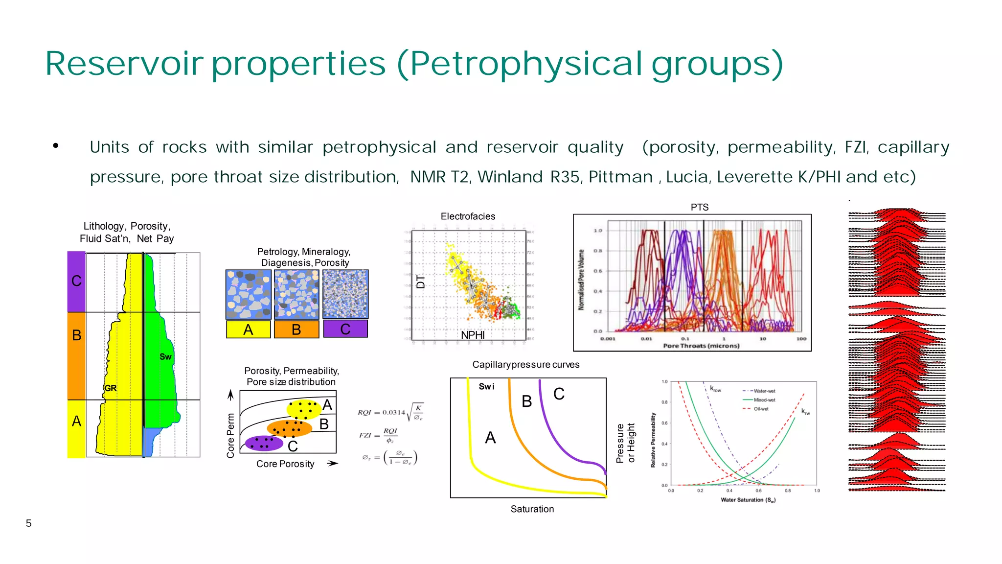
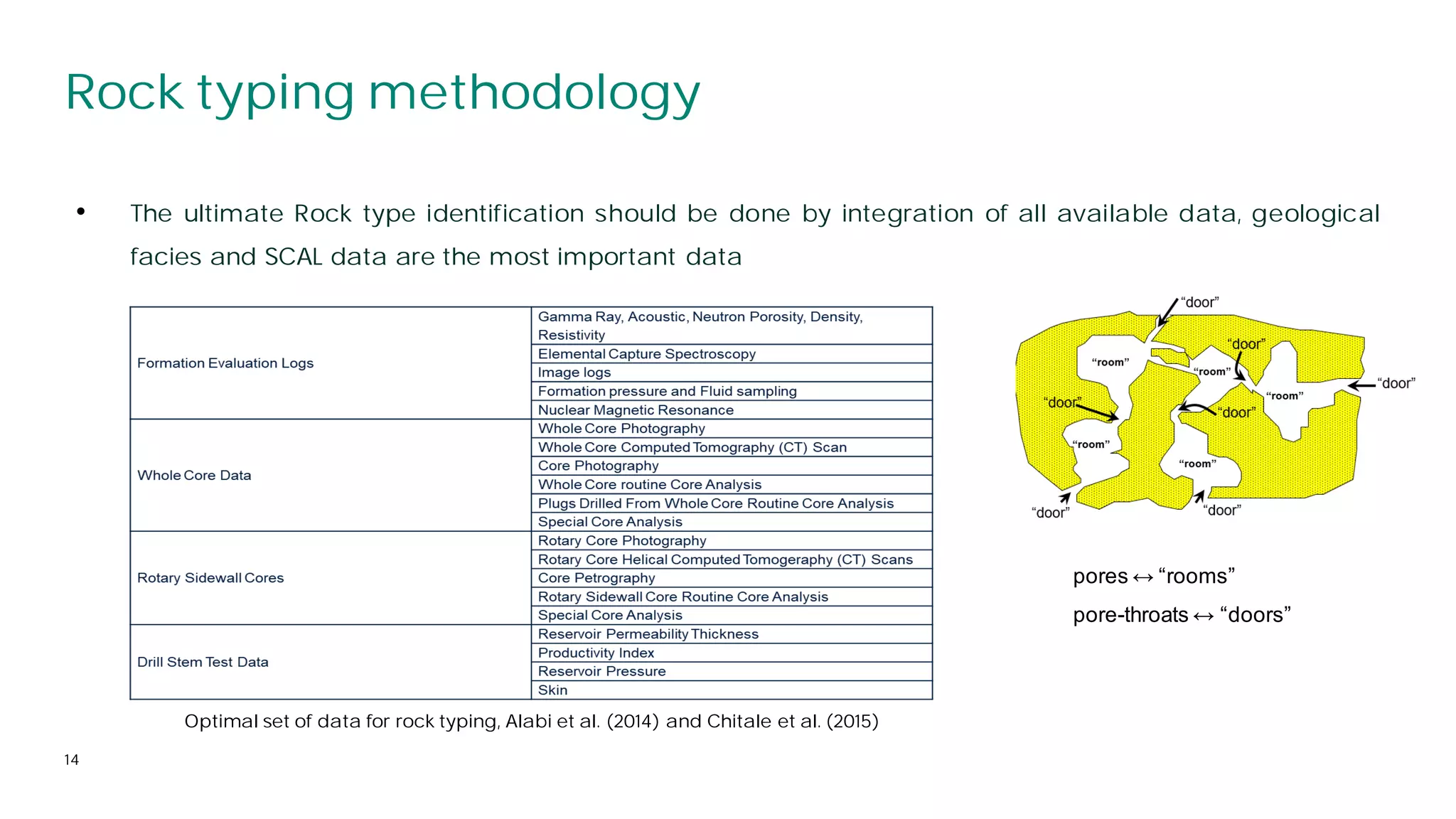
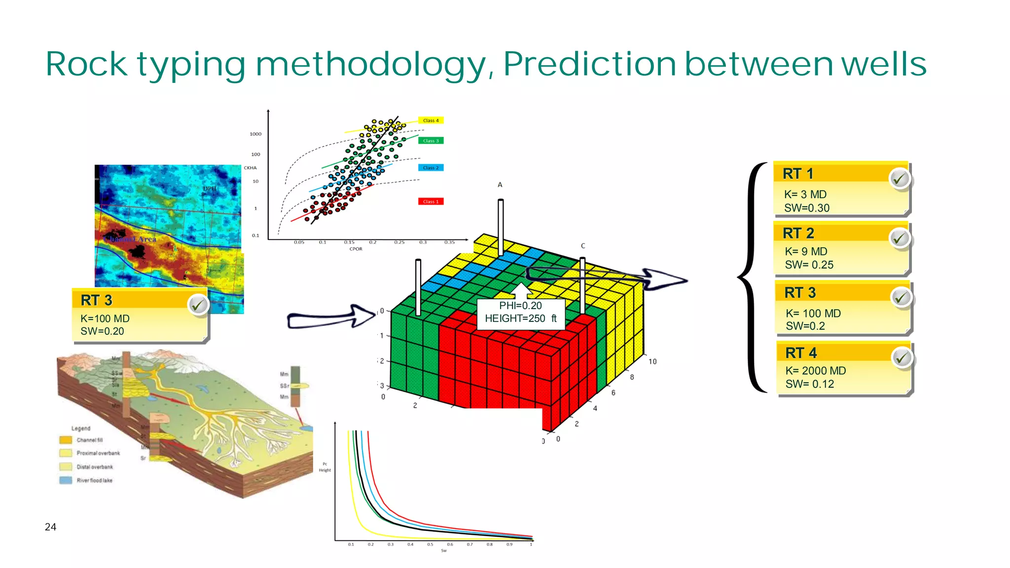
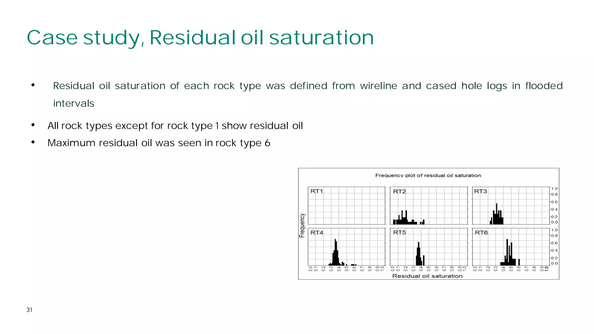
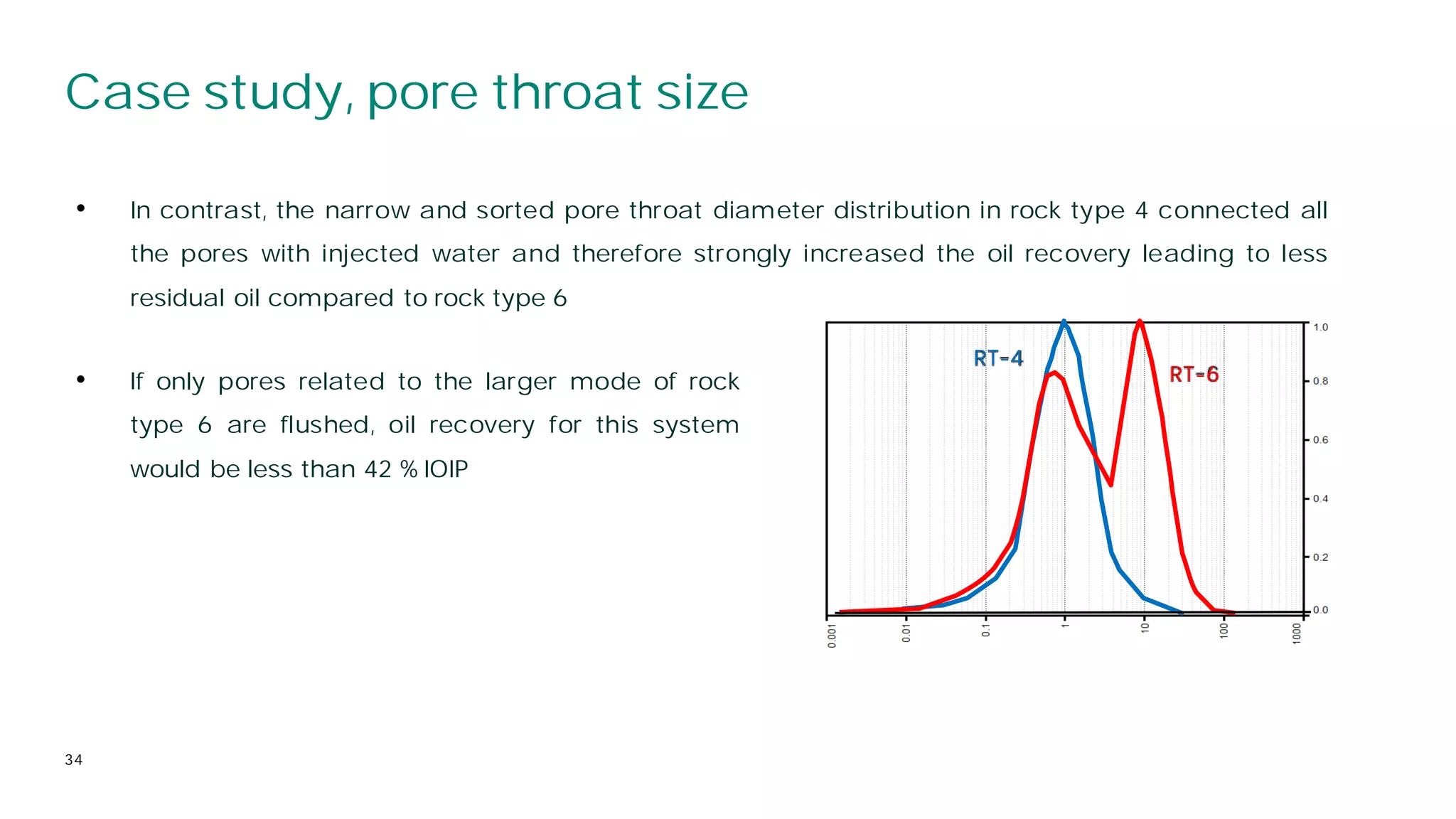
Ebrahim Heydari
ConsultantPetrophysicist
Ebrahim.Heydari@gmail.com
ROCK TYPING
Application in reservoir
modelling and development
October 15 2019
2
Outline
• Geological characterization and modelling
• Importance and objective of rock typing
• Rock typing methodology
• Rock type requirements
• Pitfalls in rock typing
• Rock typing schedule
• Example of application of rock typing study
⎯ Lithostratigraphy and chronostratigraphyunits
⎯ Petrophysical/reservoir groups (Electrofacies, Winland
⎯ Rock type
• Primary objective of geological characterization and modelling is to predict the spatial variation of
petrophysical and reservoir properties (any property that can be measured in terms of real numerical
values)
• Main inputs:
⎯ Project boundary and locations
⎯ Well data
⎯ Faults and fractures
⎯ Fluid contacts
3
Geological characterization and modelling
⎯ Horizons and tops (Zones)
⎯ Properties(petrophysicalgroups,clay content, porosity, permeability, N/Gand SHFs)
• Two forms of geological tops/zones are applied in the modeling
• They constitute the basic elements of the reservoir architecture
⎯ Lithostratigraphic: Each zone shows a different lithology, fossil content.
i.e formation
⎯ Chronostratigraphic: Each zone shows a different interval of geologic
time. i.e parasequence
4
5
Reservoir properties (Petrophysical groups)
• Units of rocks with similar petrophysical and reservoir quality (porosity, permeability, FZI, capillary
pressure, pore throat size distribution, NMR T2, Winland R35, Pittman , Lucia, Leverette K/PHI and etc)
A
B C
Swi
Pressure
or
Height
NPHI
DT
A C
B
Core
Perm
A
Core Porosity
. . ..
. .
. .
. ..
. . ..
. .
.
. ..
. .. C
B
Lithology, Porosity,
Fluid Sat’n, Net Pay
GR
Sw
C
B
A
Porosity, Permeability,
Pore size distribution
Petrology, Mineralogy,
Diagenesis,Porosity
Electrofacies
Saturation
PTS
Capillarypressure curves
6
Chronostratigraphic units vs petrophysical groups
• GENERALLY NO LINK, typically chronostratigraphic units are anisotropic, spatially complex and internally
heterogeneous. This is mainly because of change in lithology, grain size, sorting and texture
Sw vs. height
Sediment Grain PHI vs K
Crevasse Splay
Channel Fill
Proximal
Distributary
Mouth Bar
Distal
Distributary
Mouth Bar
Prodelta
Delta Front
Delta Front Sandstone
Delta Front Siltstone
Pro-Delta Shales
Offshore Clay
Sea Level
7
Lithostratigraphic units vs petrophysical groups
• GENERALLY NO LINK, sometimes link. Lithostratigraphic units could be heterogeneous. This is mainly
because of change in grain size and sorting
Porosity
Permeability
Medium to coarse sand, Mean size: 0.5 mm
Very fine sand, Mean size: 0.1 mm
Permeability
Very well sorted
Mod.-Well sorted
Very poorly sorted
Extremely poorly
sorted
Porosity
Modified after Rabiller, 2006
8
Carbonate reservoirs
• NO LINK, typically both units in carbonates are very heterogeneous. This is mainly because of
diagenesis
PHI
K
PHI
K
1
PHI
K
8
9
Definition of rock type
• HIGHLIGHT: geological zones and petrophysical groups need to be integrated by a model, ROCK TYPING
• Rock types: Units of rock deposited under similar conditions which experienced similar digenetic
processes resulting in a unique porosity-permeability relationship, capillary pressure profile and water
saturation for a given height above free water in a reservoir (Archie, 1950)
10
Rock typing objective
• The ultimate objective of rock typing is to drive a framework for rock property distribution within 3D
reservoir models that both honours the well data and predicts reservoir properties in uncored wells
and between wells (Hollis et al., 2010)
• The main Rock Typing study objective is to contribute to build dynamic model by an accurate 3D-
distribution of geological facies being petrophysically meaningful through porosity, permeability, Pc
and Kr. To achieve this point, petrophysical properties have to rely on 3D predictive variables i.e.
geological facies (Rebelle et al., 2009)
11
Rock typing methodology
• There are four main phases in each rock typing study
1- Selection of key wells
12
Rock typing methodology, Selection of key wells
• Key wells should be selected from the wells with maximum data (preferably wells with cores, Image
logs, NMR and pressure data)
• They should cover reservoir laterally and vertically to capture heterogeneity
OWC OWC
13
Rock typing methodology
1. Selecting key wells
2. Identification of rock types in key wells
14
Rock typing methodology
• The ultimate Rock type identification should be done by integration of all available data, geological
facies and SCAL data are the most important data
pores ↔ “rooms”
pore-throats ↔ “doors”
Optimal set of data for rock typing, Alabi et al. (2014) and Chitale et al. (2015)
Rock typing methodology, Identification of rock types
• Each rock type should honour followings (Varavur et al., 2005):
⎯ They must present unique reservoir behaviour
⎯ They should be predictablein un cored sections and wells
⎯ Eachrock type must be correlativeand mappablebetweenwells
Methodology, 2: Identification of rock types
15
16
Rock typing methodology, Identification of rock types
Copyright 2019 Baker Hughes CompanyLLC. All rightsreserved.
• Never forget data QC, corrections and nature of data type, for example what is the permeability in 3D
model?
• Based on review of more than 50000 SCAL experiments more than 70% of them are unfit for purpose,
(McPhee, 2015)
⎯ Air permeability?
⎯ Klinkenberg? Measured or from a correlation?
⎯ Brine permeability?
⎯ Ambient or stressed?
⎯ How measured?
⎯ How were plug prepared?
17
Rock typing methodology
Copyright 2019 Baker Hughes CompanyLLC. All rightsreserved.
1. Selecting key wells
2. Identification of rock types in key wells
3. Prediction of rock types in un cored
sections of wells and other un cored wells
18
Rock typing methodology, Prediction in un cored wells
• The relationship between rock types and common data in key wells (normally logs) is discovered for
each rock type and used to back calculate rock types
Figures from help
• If extensive core data are available
this stage is less important
1. Selecting key wells
2. Identification of rock types in key
wells
3. Prediction of rock types in un cored
sections of key wells and other un
cored wells
4. Rock type modeling (modelling
between wells in 3D model)
19
Rock typing methodology
20
Rock typing methodology, Prediction between wells
• Why prediction between wells is the most important part?
⎯ Reservoir is Arab-D, average thickness is 100 m
⎯ Vb = bulk rock volume of reservoir is 875,000,000,000 m3
(250000*35000*100)
⎯ There are more than 3400 wells in Ghawar field
⎯ Reservoir volume drilled by each well is 3.65 m3
⎯ Reservoir volume drilled by 3400 wells is 12,441 m3
⎯ Ratio of reservoir cut by wells is less than 0.000000014
Ghawar field
Rock typing methodology, Prediction between wells
21
• The spatial 3D distribution of the rock types should be predictable within the geological, geophysical or
reservoir framework (between wells)
Rock typing methodology, Prediction between wells
22
• The spatial Clear image of shape, distribution, trend and size of facies/rock types is essential to
propagate them between wells
Rock typing methodology, Prediction between wells
23
Class 3
poro-perm 3
SHF 3
Rel. perm. 3
Rock typing methodology, Prediction between wells
24
RT 3
K=100 MD
SW=0.20
RT 1
RT 2
RT 3
RT 4
PHI=0.20
HEIGHT=250 ft
K= 3 MD
SW=0.30
K= 9 MD
SW= 0.25
K= 100 MD
SW=0.2
K= 2000 MD
SW= 0.12
Rock typing methodology, Prediction between wells
25
RT 2: Reservoir
RT 1: Tight
A B D
C
5 km
RT2
RT1
RT2
RT2
RT1
RT1
RT1
RT2
Pitfalls in rock typing
26
• Rock typing without using SCAL data as the main input
• Sedimentological maps are not integrated in the process
• Sedimentological litofacies and diagenetic descriptions are not completed in a consistent approach,
preferably by the same interpreter for all wells, example from Piper
• Facies are described without diagenetic overprints
• Sampling for SCAL is done before taking into account the distribution of the petrophysical groups. (each
rock type needs a unique SCAL representative)
• Poro-perm transforms are applied without linking to geological facies and stratigraphic position
(Winland R35,Pitman and Lucia)
• Using conventional data and methods in Carbonates
• Using data without QC
Rock typing schedule
27
• Average thickness
• and properties
.
1- Exploration
3- Brown field
• 3D seismic
• Structural model with faults
• Facies/RT modelling
• Probabilistic models
• SHF
2- Green field
• 2D/3D seismic
• Simple 3D grid
• Deterministic model
4- Water flooding, EOR/EGR
• 4D seismic
• Structural model with all faults
• Facies/RTmodelling
1
2
3
4
5
Simplemodel In depthmodel
5-
Abandonment
Data
Case study
28
• Structure: 15*7 km NE-SW anticline
• Original hydrocarbon in place: 1500 MMSTB
• Early water cut: 8%
Mishrif
Laffan
Khatiyah
Case study, problem
29
• 7 exploration and delineation wells
• Production started with four wells, 15 more producer and 10 injector wells were drilled in very short time
• Shortly after start of production and water injection water cut significantly increased
• This was resulted in having lower recover factor and reserve and higher residual oil
• High water cut is a frequent problem that oil producers face at the late stage of oilfield development
and production. The main reason of this problem is water breakthrough from the injection wells trough
high permeable intervals and zones
Case study, rock typing
30
• A detailed rock typing was carried out to investigate the
effect of reservoir quality and rock types on water
flooding, residual oil and recovery factor
• Six major rock types were classified in cored wells and
subsequently predicted in un-cored wells
Case study, Residual oil saturation
31
• Residual oil saturation of each rock type was defined from wireline and cased hole logs in flooded
intervals
• All rock types except for rock type 1 show residual oil
• Maximum residual oil was seen in rock type 6
Case study, Water flooding test
32
• The Two water flood experiments on composite cores of rock type 4 and 6 were used. These tests were
carried out under reservoir conditions using oil and water similar to the actual reservoir fluids. Water
injection was carried out at a constant rate of 10 cm3/h
Compositecore
Compositecoreof rock
type4
Compositecoreof rock
type6
Reservoir quality
Porosity (%) 20 17
Air permeability (mD) 28 410
Water permeability (mD) 27 405
Permeability to reservoir oil at Swi
(mD)
27 398
Irreducible water saturation (Swi) 13.6 17.3
Test
Initial injection rate (cm3/h) 10 10
Front advance velocity (m/day) 0.34 0.81
Water Pore volume (PV) injected 31.1 15.3
breakthrough Cumulativeoil recovery (%IOIP) 27.4 16.2
End of water flood at 10 cm3/h
Pore volume (PV) injected 537.7 432
Oil recovery (%IOIP) 53.4 21.7
Sor (%) 35.8 67.6
• Composite core of rock type
6 presents an earlier water
breakthrough and higher Sor
compared to the composite
core of rock type 4 (similar
observation in CPIs)
Case study, Pore throat size
33
• Rock type 6 presents a dual pore throat diameter distribution. It appears that only pores related to the
larger mode of pore throat diameter distribution (larger than 5-10 micron) have been water flooded. In
this rock type, water typically follows a preferential flow path through the high permeability zones and
consequently some oil is by-passed
Before
water flooding
After
water flooding
RT-4 RT-6
Oil Water
Case study, pore throat size
34
• In contrast, the narrow and sorted pore throat diameter distribution in rock type 4 connected all
the pores with injected water and therefore strongly increased the oil recovery leading to less
residual oil compared to rock type 6
RT-4
RT-6
• If only pores related to the larger mode of rock
type 6 are flushed, oil recovery for this system
would be less than 42 % IOIP
Conclusions
35
• Rock-typing is a synergetic workflow between the geologist, petrophysicist and reservoir engineer and
the accurate determination and propagation of rock types requires a comprehensive integration of
petrophysical, geological and reservoir data
• No matter what software or prediction technique we apply to a variable, we are unlikely to achieve an
acceptable result unless we take geological facts/effects into account
Summary of selected rock typing studies typing
studies
37
Reference Formation/ Location
Rock Type
Definitions
Data Sources / Evaluation Methodologies
Davies, et al. [1991]
Travis Peak sands, East Texas
Salt Basin
No specific
definitions
Depositional environments, sand body geometry,
dimensions from core descriptions
Texture, composition, lithology from microscopic
imaging
No quantitative porosity-permeability ranges;
provided qualitative indicators
Porras, et al. [1999]
Santa Barbara and Pirital Field
sands, Eastern Venezuela Basin
Lithofacies,
petrofacies
Physical core descriptions of both large-scale &
small-scale features; microscopic imaging of texture,
composition, lithology, diagenesis
Core-based measurement of porosity,
permeability; dominant pore throat diameter from
mercury-injection capillary pressure data
Davies, et al. [1999]
Wilmington Field Pliocene-Age
sands
No specific
definitions
Depositional environments, sand body geometry,
dimensions from core descriptions
Texture, composition, lithology from microscopic
imaging
No quantitative porosity-permeability ranges;
provided qualitative indicators
Boada, et al. [2001]
Santa Rosa Field, Eastern
Venezuela Basin
Lithofacies,
petrofacies
Physical core descriptions of both large-scale &
small-scale features; microscopic imaging of texture,
composition, lithology, diagenesis
Core-based measurement of porosity,
permeability; dominant pore throat diameter from
mercury-injection capillary pressure data
Leal, et al. [2001]
Block IX sands, Lake Maracaibo
Basin, Venezuela
Lithofacies,
petrofacies
Physical core descriptions of both large-scale &
small-scale features; microscopic imaging of texture,
composition, lithology, diagenesis
Core-based measurement of porosity,
permeability; dominant pore throat diameter from
mercury-injection capillary pressure data
Summary of selected rock typing studieses
38
Reference Formation/Location Rock TypeDefinitions Data Sources / Evaluation Methodologies
Madariage, et al. [2001]
Sandstone/ C4 & C5 sands,
Lagunillas Field, Lake Maracaibo
Basin, Venezuela
Lithofacies, petrofacies
Physical core descriptions of both large-scale & small-
scale features; microscopic imaging of texture, composition,
lithology, diagenesis
Core-based measurement of porosity, permeability,
electrical properties; dominant pore throat diameter from
mercury-injection capillary pressure data
Porras, et al. [2001]
Tertiary & Cretaceous sands, Santa
Barbara Field, Eastern Venezuela
Basin
No specific definitions
Physical core descriptions of both large-scale & small-
scale features; microscopic imaging of texture, composition,
lithology, diagenesis
Core-based measurement of porosity, permeability;
dominant pore throat diameter from mercury-injection
capillary pressure data
Soto, et al. [2001]
K1 sands, Suria
No specific definitions
Core-based measurement of porosity, permeability;
dominant pore throat diameter from mercury-injection
capillary pressure data
& Reforma- Libertad Fields, Used fuzzy logic to predict rock types in uncored wells
Apiay-Ariari Basin, Columbia
Marquez, et al. [2001]
LL-04 sands, Tia
Lithofacies, petrofacies
Identification of stratigraphic units and lithofacies from
log analysis
Juana Field, Lake Maracaibo Basin,
Venezuela
Physical core descriptions of small-scale features;
microscopic imaging of texture, composition, lithology
Core-based measurement of porosity, permeability; up
scaled permeability using NMR log measurements
Ali-Nandalal & Gunter
[2003]
Pliestocene-age Geological facies,
Petrophysical rock
types
Facies identified using core- and log-based analyses of
primary sedimentary structures
sands, Mahogany Field, Columbus
Basin, Venezuela
Core-based measurement of porosity, permeability and
electrical properties
Summary of selected rock typing studies
39
Reference Formation/Location
Rock Type
Definitions
Data Sources / Evaluation Methodologies
Ohen, et al. [2004]
Shushufindi Field sands, Oriente
Basin, Ecuador
Geological facies
Facies identified using core- and log-based analyses of
stratigraphy, structure, depositional environment
Core-based measurement of porosity, permeability and
water saturation
Acosta, et al. [2005] El Furrial Field sands, Venezuela
Geological facies,
Petrophysical rock
types
Facies identified using core- and log-based analyses of
stratigraphy, structure, depositional environment
Core-based measurement of porosity, permeability and
water saturation; pore characteristics from mercury-
injection capillary pressure data
Guo, et al. [2005]
Napo formation sands, Oriente
Basin, Ecuador
Petrophysical rock
type
-based measurement of porosity, permeability and
water saturation; pore characteristics from mercury-
injection capillary pressure data
Shenawi, et al. [2007]
Formation unknown,location
unknown
Geological facies,
Petrophysical rock
types
Facies identified using log-based definitions of shale
content, lithology (density log)
Core-based measurement of porosity, permeability and
water saturation; pore characteristics from mercury-
injection capillary pressure data
Neo, et al. [1998]; Grotsch,
et al.
Lower Cretaceous-age Thamama I,
II, II reservoirs, offshore Abu Dhabi
Depositional
Depositional environments, lithologies identified from
core-based descriptions and log-based analysis
[1998]; Marzouk, et al..
[1998]; Al-Aruri, et al. [1998]
facies, Lithofacies,
Petrophysical rock
types
Petrophysical properties including lithology, grain size &
distribution from microscopic imaging; porosity,
permeability determined from core analysis; pore
structure & geometry determined from mercury-injection
capillary pressure data
Mathisen, et al. [2001]
Upper & lower Clearfork formations,
North Robertson Unit, Gaines Co., TX
Lithofacies,
Electrofacies
Geological interpretations & log response to identify basic
lithofacies
Log-based descriptions based on similarity of log
responses reflecting differences in mineralogy & lithofacies
Summary of selected rock typing studies
40
Reference Formation/Location Rock TypeDefinitions Data Sources / Evaluation Methodologies
Lee, et al. [2002]; Perez,
at al. [2003, 2005
C1a, C1b, C2a,, C2b, C3-C5
Lithofacies,
Electrofacies
Identified lithofacies using core-based descriptions &
microscopic imaging
zones, Northwest Extension
carbonate buildup, Salt Creek
Field, Kent Co., TX
Identified electrofacies using log-based descriptions based
on similarity of log responses reflecting differences in
mineralogy & lithofacies
Aplin, et al. [2002]
Lower Cretaceous-age
Lithofacies, Reservoir
rock type
Identified lithofacies using log-based similarities in micro-
resistivity curves; calibrated to core-based descriptions
Thamama Group, onshore U.A.E.
Identified reservoir rock types from core-based physical
descriptions, microscopic imaging; evaluated porosity,
permeability from core measurements; determined pore
structure & dimensions from mercury- capillary pressure
data
Al-Habshi, at al. [2003]
Upper Zakum Formation, Field
"B", onshore Abu Dhabi
Lithofacies
Identified lithofacies from geological interpretations, log and
core analyses, and paragenetic sequence analysis
Determined physical properties from core measurements;
identified diagenesis from microscopic imaging; determined
pore structure & dimensions from mercury-injection capillary
pressure data
Bieranvand [2003]
Upper Cennomanian carbonate
reservoir
Lithofacies, reservoir
rock types
Identified lithofacies from geological interpretations and
core-based physical descriptions
Evaluated permeability & porosity from routine core analysis;
quantified pore structure using mercury-injection capillary
pressure data
Al-Farisi, et al. [2004] Offshore Abu Dhabi carbonate Electrofacies
Evaluated rock fabric & texture from core studies; measured
permeability & porosity from routine core analysis, measured
pore structure from mercury- injection capillary pressure data
Up scaled core-based rock types to electrofacies using log
response
Summary of selected rock typing studies
41
Reference Formation/ Location Rock Type Definitions Data Sources / Evaluation Methodologies
Meyer, et al. [2004]
K1-K4 intervals, Upper Khuff
Formation, offshore Abu
Dhabi
Lithofacies, Static rock
types
Depositional environments, lithologies identified from
geological interpretations, core-based descriptions and
log-based analysis
Identified static rock types based on pore types
determined from microscopic imaging and mercury-
injection capillary pressure data
Varavur, et al. [2005] No information
Lithofacies, Petrophysical
rock types
Identified lithofacies from geological interpretations and
core-based physical descriptions; lithofacies defined
based on depositional texture, grain-size, sorting,
diagenesis
Evaluated permeability & porosity from routine core
analysis; quantified pore structure using microscopic
imaging and mercury-injection capillary pressure data
Rebelle, et al. [2005]
Lower Kharaib
Lithofacies, Petrophysical
rock types
Identified lithofacies from geological interpretations
and core-based physical descriptions; lithofacies defined
based on depositional texture, lithology, diagenesis
formation, onshore Abu
Dhabi
Evaluated permeability & porosity from routine core
analysis; quantified pore structure using mercury-injection
capillary pressure data
Frank, et al. [2005]
Shuaiba formation, Al
Shaheen Field, offshore
Qatar
No definitions
Identified rock types using routine core measurements,
microscopic imaging, mercury-injection capillary pressure
data, NMR characteristics
Up scaled rock types using NMR logs
Creusen, et al. [2007] Natih formation, Oman
Primary rock types, Rock
Primary rock types identified on pore scale using
microscopic imaging as well as routine porosity &
permeability measurements
type associations
Rock type associations reflect collections of primary rock
types, pore types and size distribution

Rock Typing.pdf

  • 1.
  • 2.
    2 Outline • Geological characterizationand modelling • Importance and objective of rock typing • Rock typing methodology • Rock type requirements • Pitfalls in rock typing • Rock typing schedule • Example of application of rock typing study ⎯ Lithostratigraphy and chronostratigraphyunits ⎯ Petrophysical/reservoir groups (Electrofacies, Winland ⎯ Rock type
  • 3.
    • Primary objectiveof geological characterization and modelling is to predict the spatial variation of petrophysical and reservoir properties (any property that can be measured in terms of real numerical values) • Main inputs: ⎯ Project boundary and locations ⎯ Well data ⎯ Faults and fractures ⎯ Fluid contacts 3 Geological characterization and modelling ⎯ Horizons and tops (Zones) ⎯ Properties(petrophysicalgroups,clay content, porosity, permeability, N/Gand SHFs)
  • 4.
    • Two formsof geological tops/zones are applied in the modeling • They constitute the basic elements of the reservoir architecture ⎯ Lithostratigraphic: Each zone shows a different lithology, fossil content. i.e formation ⎯ Chronostratigraphic: Each zone shows a different interval of geologic time. i.e parasequence 4
  • 5.
    5 Reservoir properties (Petrophysicalgroups) • Units of rocks with similar petrophysical and reservoir quality (porosity, permeability, FZI, capillary pressure, pore throat size distribution, NMR T2, Winland R35, Pittman , Lucia, Leverette K/PHI and etc) A B C Swi Pressure or Height NPHI DT A C B Core Perm A Core Porosity . . .. . . . . . .. . . .. . . . . .. . .. C B Lithology, Porosity, Fluid Sat’n, Net Pay GR Sw C B A Porosity, Permeability, Pore size distribution Petrology, Mineralogy, Diagenesis,Porosity Electrofacies Saturation PTS Capillarypressure curves
  • 6.
    6 Chronostratigraphic units vspetrophysical groups • GENERALLY NO LINK, typically chronostratigraphic units are anisotropic, spatially complex and internally heterogeneous. This is mainly because of change in lithology, grain size, sorting and texture Sw vs. height Sediment Grain PHI vs K Crevasse Splay Channel Fill Proximal Distributary Mouth Bar Distal Distributary Mouth Bar Prodelta Delta Front Delta Front Sandstone Delta Front Siltstone Pro-Delta Shales Offshore Clay Sea Level
  • 7.
    7 Lithostratigraphic units vspetrophysical groups • GENERALLY NO LINK, sometimes link. Lithostratigraphic units could be heterogeneous. This is mainly because of change in grain size and sorting Porosity Permeability Medium to coarse sand, Mean size: 0.5 mm Very fine sand, Mean size: 0.1 mm Permeability Very well sorted Mod.-Well sorted Very poorly sorted Extremely poorly sorted Porosity Modified after Rabiller, 2006
  • 8.
    8 Carbonate reservoirs • NOLINK, typically both units in carbonates are very heterogeneous. This is mainly because of diagenesis PHI K PHI K 1 PHI K 8
  • 9.
    9 Definition of rocktype • HIGHLIGHT: geological zones and petrophysical groups need to be integrated by a model, ROCK TYPING • Rock types: Units of rock deposited under similar conditions which experienced similar digenetic processes resulting in a unique porosity-permeability relationship, capillary pressure profile and water saturation for a given height above free water in a reservoir (Archie, 1950)
  • 10.
    10 Rock typing objective •The ultimate objective of rock typing is to drive a framework for rock property distribution within 3D reservoir models that both honours the well data and predicts reservoir properties in uncored wells and between wells (Hollis et al., 2010) • The main Rock Typing study objective is to contribute to build dynamic model by an accurate 3D- distribution of geological facies being petrophysically meaningful through porosity, permeability, Pc and Kr. To achieve this point, petrophysical properties have to rely on 3D predictive variables i.e. geological facies (Rebelle et al., 2009)
  • 11.
    11 Rock typing methodology •There are four main phases in each rock typing study 1- Selection of key wells
  • 12.
    12 Rock typing methodology,Selection of key wells • Key wells should be selected from the wells with maximum data (preferably wells with cores, Image logs, NMR and pressure data) • They should cover reservoir laterally and vertically to capture heterogeneity OWC OWC
  • 13.
    13 Rock typing methodology 1.Selecting key wells 2. Identification of rock types in key wells
  • 14.
    14 Rock typing methodology •The ultimate Rock type identification should be done by integration of all available data, geological facies and SCAL data are the most important data pores ↔ “rooms” pore-throats ↔ “doors” Optimal set of data for rock typing, Alabi et al. (2014) and Chitale et al. (2015)
  • 15.
    Rock typing methodology,Identification of rock types • Each rock type should honour followings (Varavur et al., 2005): ⎯ They must present unique reservoir behaviour ⎯ They should be predictablein un cored sections and wells ⎯ Eachrock type must be correlativeand mappablebetweenwells Methodology, 2: Identification of rock types 15
  • 16.
    16 Rock typing methodology,Identification of rock types Copyright 2019 Baker Hughes CompanyLLC. All rightsreserved. • Never forget data QC, corrections and nature of data type, for example what is the permeability in 3D model? • Based on review of more than 50000 SCAL experiments more than 70% of them are unfit for purpose, (McPhee, 2015) ⎯ Air permeability? ⎯ Klinkenberg? Measured or from a correlation? ⎯ Brine permeability? ⎯ Ambient or stressed? ⎯ How measured? ⎯ How were plug prepared?
  • 17.
    17 Rock typing methodology Copyright2019 Baker Hughes CompanyLLC. All rightsreserved. 1. Selecting key wells 2. Identification of rock types in key wells 3. Prediction of rock types in un cored sections of wells and other un cored wells
  • 18.
    18 Rock typing methodology,Prediction in un cored wells • The relationship between rock types and common data in key wells (normally logs) is discovered for each rock type and used to back calculate rock types Figures from help • If extensive core data are available this stage is less important
  • 19.
    1. Selecting keywells 2. Identification of rock types in key wells 3. Prediction of rock types in un cored sections of key wells and other un cored wells 4. Rock type modeling (modelling between wells in 3D model) 19 Rock typing methodology
  • 20.
    20 Rock typing methodology,Prediction between wells • Why prediction between wells is the most important part? ⎯ Reservoir is Arab-D, average thickness is 100 m ⎯ Vb = bulk rock volume of reservoir is 875,000,000,000 m3 (250000*35000*100) ⎯ There are more than 3400 wells in Ghawar field ⎯ Reservoir volume drilled by each well is 3.65 m3 ⎯ Reservoir volume drilled by 3400 wells is 12,441 m3 ⎯ Ratio of reservoir cut by wells is less than 0.000000014 Ghawar field
  • 21.
    Rock typing methodology,Prediction between wells 21 • The spatial 3D distribution of the rock types should be predictable within the geological, geophysical or reservoir framework (between wells)
  • 22.
    Rock typing methodology,Prediction between wells 22 • The spatial Clear image of shape, distribution, trend and size of facies/rock types is essential to propagate them between wells
  • 23.
    Rock typing methodology,Prediction between wells 23 Class 3 poro-perm 3 SHF 3 Rel. perm. 3
  • 24.
    Rock typing methodology,Prediction between wells 24 RT 3 K=100 MD SW=0.20 RT 1 RT 2 RT 3 RT 4 PHI=0.20 HEIGHT=250 ft K= 3 MD SW=0.30 K= 9 MD SW= 0.25 K= 100 MD SW=0.2 K= 2000 MD SW= 0.12
  • 25.
    Rock typing methodology,Prediction between wells 25 RT 2: Reservoir RT 1: Tight A B D C 5 km RT2 RT1 RT2 RT2 RT1 RT1 RT1 RT2
  • 26.
    Pitfalls in rocktyping 26 • Rock typing without using SCAL data as the main input • Sedimentological maps are not integrated in the process • Sedimentological litofacies and diagenetic descriptions are not completed in a consistent approach, preferably by the same interpreter for all wells, example from Piper • Facies are described without diagenetic overprints • Sampling for SCAL is done before taking into account the distribution of the petrophysical groups. (each rock type needs a unique SCAL representative) • Poro-perm transforms are applied without linking to geological facies and stratigraphic position (Winland R35,Pitman and Lucia) • Using conventional data and methods in Carbonates • Using data without QC
  • 27.
    Rock typing schedule 27 •Average thickness • and properties . 1- Exploration 3- Brown field • 3D seismic • Structural model with faults • Facies/RT modelling • Probabilistic models • SHF 2- Green field • 2D/3D seismic • Simple 3D grid • Deterministic model 4- Water flooding, EOR/EGR • 4D seismic • Structural model with all faults • Facies/RTmodelling 1 2 3 4 5 Simplemodel In depthmodel 5- Abandonment Data
  • 28.
    Case study 28 • Structure:15*7 km NE-SW anticline • Original hydrocarbon in place: 1500 MMSTB • Early water cut: 8% Mishrif Laffan Khatiyah
  • 29.
    Case study, problem 29 •7 exploration and delineation wells • Production started with four wells, 15 more producer and 10 injector wells were drilled in very short time • Shortly after start of production and water injection water cut significantly increased • This was resulted in having lower recover factor and reserve and higher residual oil • High water cut is a frequent problem that oil producers face at the late stage of oilfield development and production. The main reason of this problem is water breakthrough from the injection wells trough high permeable intervals and zones
  • 30.
    Case study, rocktyping 30 • A detailed rock typing was carried out to investigate the effect of reservoir quality and rock types on water flooding, residual oil and recovery factor • Six major rock types were classified in cored wells and subsequently predicted in un-cored wells
  • 31.
    Case study, Residualoil saturation 31 • Residual oil saturation of each rock type was defined from wireline and cased hole logs in flooded intervals • All rock types except for rock type 1 show residual oil • Maximum residual oil was seen in rock type 6
  • 32.
    Case study, Waterflooding test 32 • The Two water flood experiments on composite cores of rock type 4 and 6 were used. These tests were carried out under reservoir conditions using oil and water similar to the actual reservoir fluids. Water injection was carried out at a constant rate of 10 cm3/h Compositecore Compositecoreof rock type4 Compositecoreof rock type6 Reservoir quality Porosity (%) 20 17 Air permeability (mD) 28 410 Water permeability (mD) 27 405 Permeability to reservoir oil at Swi (mD) 27 398 Irreducible water saturation (Swi) 13.6 17.3 Test Initial injection rate (cm3/h) 10 10 Front advance velocity (m/day) 0.34 0.81 Water Pore volume (PV) injected 31.1 15.3 breakthrough Cumulativeoil recovery (%IOIP) 27.4 16.2 End of water flood at 10 cm3/h Pore volume (PV) injected 537.7 432 Oil recovery (%IOIP) 53.4 21.7 Sor (%) 35.8 67.6 • Composite core of rock type 6 presents an earlier water breakthrough and higher Sor compared to the composite core of rock type 4 (similar observation in CPIs)
  • 33.
    Case study, Porethroat size 33 • Rock type 6 presents a dual pore throat diameter distribution. It appears that only pores related to the larger mode of pore throat diameter distribution (larger than 5-10 micron) have been water flooded. In this rock type, water typically follows a preferential flow path through the high permeability zones and consequently some oil is by-passed Before water flooding After water flooding RT-4 RT-6 Oil Water
  • 34.
    Case study, porethroat size 34 • In contrast, the narrow and sorted pore throat diameter distribution in rock type 4 connected all the pores with injected water and therefore strongly increased the oil recovery leading to less residual oil compared to rock type 6 RT-4 RT-6 • If only pores related to the larger mode of rock type 6 are flushed, oil recovery for this system would be less than 42 % IOIP
  • 35.
    Conclusions 35 • Rock-typing isa synergetic workflow between the geologist, petrophysicist and reservoir engineer and the accurate determination and propagation of rock types requires a comprehensive integration of petrophysical, geological and reservoir data • No matter what software or prediction technique we apply to a variable, we are unlikely to achieve an acceptable result unless we take geological facts/effects into account
  • 37.
    Summary of selectedrock typing studies typing studies 37 Reference Formation/ Location Rock Type Definitions Data Sources / Evaluation Methodologies Davies, et al. [1991] Travis Peak sands, East Texas Salt Basin No specific definitions Depositional environments, sand body geometry, dimensions from core descriptions Texture, composition, lithology from microscopic imaging No quantitative porosity-permeability ranges; provided qualitative indicators Porras, et al. [1999] Santa Barbara and Pirital Field sands, Eastern Venezuela Basin Lithofacies, petrofacies Physical core descriptions of both large-scale & small-scale features; microscopic imaging of texture, composition, lithology, diagenesis Core-based measurement of porosity, permeability; dominant pore throat diameter from mercury-injection capillary pressure data Davies, et al. [1999] Wilmington Field Pliocene-Age sands No specific definitions Depositional environments, sand body geometry, dimensions from core descriptions Texture, composition, lithology from microscopic imaging No quantitative porosity-permeability ranges; provided qualitative indicators Boada, et al. [2001] Santa Rosa Field, Eastern Venezuela Basin Lithofacies, petrofacies Physical core descriptions of both large-scale & small-scale features; microscopic imaging of texture, composition, lithology, diagenesis Core-based measurement of porosity, permeability; dominant pore throat diameter from mercury-injection capillary pressure data Leal, et al. [2001] Block IX sands, Lake Maracaibo Basin, Venezuela Lithofacies, petrofacies Physical core descriptions of both large-scale & small-scale features; microscopic imaging of texture, composition, lithology, diagenesis Core-based measurement of porosity, permeability; dominant pore throat diameter from mercury-injection capillary pressure data
  • 38.
    Summary of selectedrock typing studieses 38 Reference Formation/Location Rock TypeDefinitions Data Sources / Evaluation Methodologies Madariage, et al. [2001] Sandstone/ C4 & C5 sands, Lagunillas Field, Lake Maracaibo Basin, Venezuela Lithofacies, petrofacies Physical core descriptions of both large-scale & small- scale features; microscopic imaging of texture, composition, lithology, diagenesis Core-based measurement of porosity, permeability, electrical properties; dominant pore throat diameter from mercury-injection capillary pressure data Porras, et al. [2001] Tertiary & Cretaceous sands, Santa Barbara Field, Eastern Venezuela Basin No specific definitions Physical core descriptions of both large-scale & small- scale features; microscopic imaging of texture, composition, lithology, diagenesis Core-based measurement of porosity, permeability; dominant pore throat diameter from mercury-injection capillary pressure data Soto, et al. [2001] K1 sands, Suria No specific definitions Core-based measurement of porosity, permeability; dominant pore throat diameter from mercury-injection capillary pressure data & Reforma- Libertad Fields, Used fuzzy logic to predict rock types in uncored wells Apiay-Ariari Basin, Columbia Marquez, et al. [2001] LL-04 sands, Tia Lithofacies, petrofacies Identification of stratigraphic units and lithofacies from log analysis Juana Field, Lake Maracaibo Basin, Venezuela Physical core descriptions of small-scale features; microscopic imaging of texture, composition, lithology Core-based measurement of porosity, permeability; up scaled permeability using NMR log measurements Ali-Nandalal & Gunter [2003] Pliestocene-age Geological facies, Petrophysical rock types Facies identified using core- and log-based analyses of primary sedimentary structures sands, Mahogany Field, Columbus Basin, Venezuela Core-based measurement of porosity, permeability and electrical properties
  • 39.
    Summary of selectedrock typing studies 39 Reference Formation/Location Rock Type Definitions Data Sources / Evaluation Methodologies Ohen, et al. [2004] Shushufindi Field sands, Oriente Basin, Ecuador Geological facies Facies identified using core- and log-based analyses of stratigraphy, structure, depositional environment Core-based measurement of porosity, permeability and water saturation Acosta, et al. [2005] El Furrial Field sands, Venezuela Geological facies, Petrophysical rock types Facies identified using core- and log-based analyses of stratigraphy, structure, depositional environment Core-based measurement of porosity, permeability and water saturation; pore characteristics from mercury- injection capillary pressure data Guo, et al. [2005] Napo formation sands, Oriente Basin, Ecuador Petrophysical rock type -based measurement of porosity, permeability and water saturation; pore characteristics from mercury- injection capillary pressure data Shenawi, et al. [2007] Formation unknown,location unknown Geological facies, Petrophysical rock types Facies identified using log-based definitions of shale content, lithology (density log) Core-based measurement of porosity, permeability and water saturation; pore characteristics from mercury- injection capillary pressure data Neo, et al. [1998]; Grotsch, et al. Lower Cretaceous-age Thamama I, II, II reservoirs, offshore Abu Dhabi Depositional Depositional environments, lithologies identified from core-based descriptions and log-based analysis [1998]; Marzouk, et al.. [1998]; Al-Aruri, et al. [1998] facies, Lithofacies, Petrophysical rock types Petrophysical properties including lithology, grain size & distribution from microscopic imaging; porosity, permeability determined from core analysis; pore structure & geometry determined from mercury-injection capillary pressure data Mathisen, et al. [2001] Upper & lower Clearfork formations, North Robertson Unit, Gaines Co., TX Lithofacies, Electrofacies Geological interpretations & log response to identify basic lithofacies Log-based descriptions based on similarity of log responses reflecting differences in mineralogy & lithofacies
  • 40.
    Summary of selectedrock typing studies 40 Reference Formation/Location Rock TypeDefinitions Data Sources / Evaluation Methodologies Lee, et al. [2002]; Perez, at al. [2003, 2005 C1a, C1b, C2a,, C2b, C3-C5 Lithofacies, Electrofacies Identified lithofacies using core-based descriptions & microscopic imaging zones, Northwest Extension carbonate buildup, Salt Creek Field, Kent Co., TX Identified electrofacies using log-based descriptions based on similarity of log responses reflecting differences in mineralogy & lithofacies Aplin, et al. [2002] Lower Cretaceous-age Lithofacies, Reservoir rock type Identified lithofacies using log-based similarities in micro- resistivity curves; calibrated to core-based descriptions Thamama Group, onshore U.A.E. Identified reservoir rock types from core-based physical descriptions, microscopic imaging; evaluated porosity, permeability from core measurements; determined pore structure & dimensions from mercury- capillary pressure data Al-Habshi, at al. [2003] Upper Zakum Formation, Field "B", onshore Abu Dhabi Lithofacies Identified lithofacies from geological interpretations, log and core analyses, and paragenetic sequence analysis Determined physical properties from core measurements; identified diagenesis from microscopic imaging; determined pore structure & dimensions from mercury-injection capillary pressure data Bieranvand [2003] Upper Cennomanian carbonate reservoir Lithofacies, reservoir rock types Identified lithofacies from geological interpretations and core-based physical descriptions Evaluated permeability & porosity from routine core analysis; quantified pore structure using mercury-injection capillary pressure data Al-Farisi, et al. [2004] Offshore Abu Dhabi carbonate Electrofacies Evaluated rock fabric & texture from core studies; measured permeability & porosity from routine core analysis, measured pore structure from mercury- injection capillary pressure data Up scaled core-based rock types to electrofacies using log response
  • 41.
    Summary of selectedrock typing studies 41 Reference Formation/ Location Rock Type Definitions Data Sources / Evaluation Methodologies Meyer, et al. [2004] K1-K4 intervals, Upper Khuff Formation, offshore Abu Dhabi Lithofacies, Static rock types Depositional environments, lithologies identified from geological interpretations, core-based descriptions and log-based analysis Identified static rock types based on pore types determined from microscopic imaging and mercury- injection capillary pressure data Varavur, et al. [2005] No information Lithofacies, Petrophysical rock types Identified lithofacies from geological interpretations and core-based physical descriptions; lithofacies defined based on depositional texture, grain-size, sorting, diagenesis Evaluated permeability & porosity from routine core analysis; quantified pore structure using microscopic imaging and mercury-injection capillary pressure data Rebelle, et al. [2005] Lower Kharaib Lithofacies, Petrophysical rock types Identified lithofacies from geological interpretations and core-based physical descriptions; lithofacies defined based on depositional texture, lithology, diagenesis formation, onshore Abu Dhabi Evaluated permeability & porosity from routine core analysis; quantified pore structure using mercury-injection capillary pressure data Frank, et al. [2005] Shuaiba formation, Al Shaheen Field, offshore Qatar No definitions Identified rock types using routine core measurements, microscopic imaging, mercury-injection capillary pressure data, NMR characteristics Up scaled rock types using NMR logs Creusen, et al. [2007] Natih formation, Oman Primary rock types, Rock Primary rock types identified on pore scale using microscopic imaging as well as routine porosity & permeability measurements type associations Rock type associations reflect collections of primary rock types, pore types and size distribution