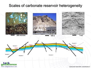
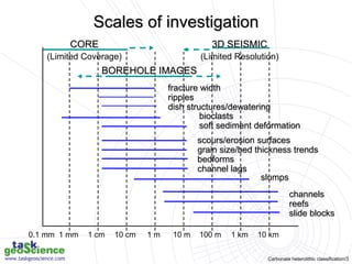
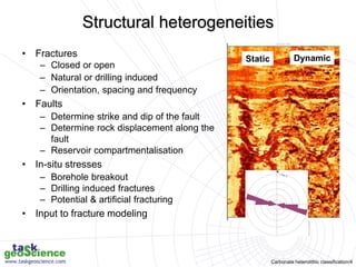
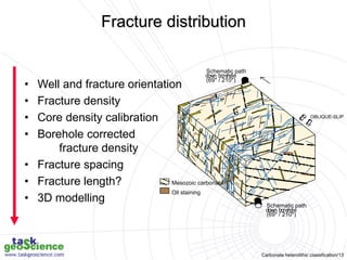
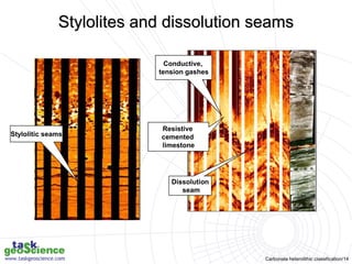
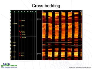
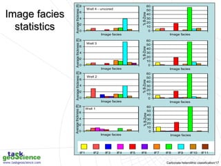
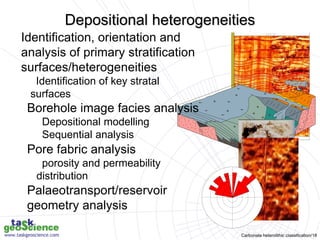
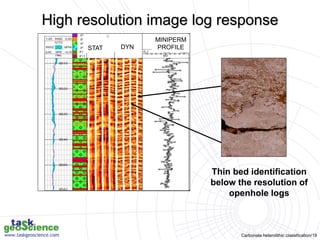
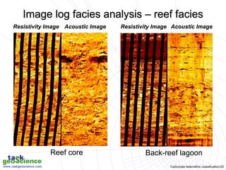
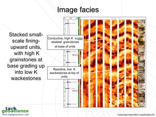
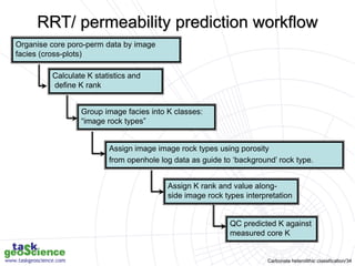
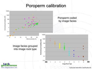
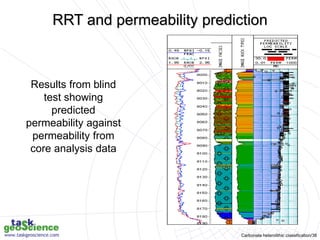
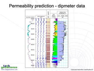
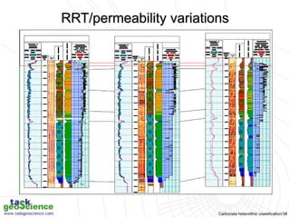
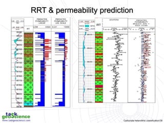
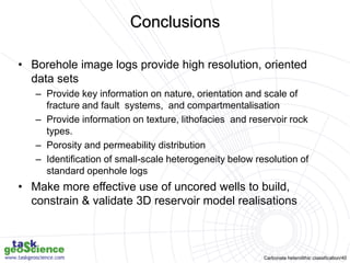
Carbonate heterolithic classification/1
1 km
100 m
200 microns
Scales of carbonate reservoir heterogeneity
Carbonate heterolithic classification/2
Image log & dipmeter analysis course
Characterisation of carbonate reservoir
heterogeneity using borehole image logs
Carbonate heterolithic classification/3
channels
reefs
slide blocks
0.1 mm 100 m 1 km 10 km
1 m 10 m
1 cm 10 cm
1 mm
CORE
(Limited Coverage)
BOREHOLE IMAGES
3D SEISMIC
(Limited Resolution)
fracture width
ripples
dish structures/dewatering
bioclasts
soft sediment deformation
scours/erosion surfaces
grain size/bed thickness trends
bedforms
channel lags
slumps
Scales of investigation
Carbonate heterolithic classification/4
• Fractures
– Closed or open
– Natural or drilling induced
– Orientation, spacing and frequency
• Faults
– Determine strike and dip of the fault
– Determine rock displacement along the
fault
– Reservoir compartmentalisation
• In-situ stresses
– Borehole breakout
– Drilling induced fractures
– Potential & artificial fracturing
• Input to fracture modeling
Static Dynamic
36 72
N
Structural heterogeneities
Carbonate heterolithic classification/5
• Borehole imaging tools
• Heterogeneities
– Structural – fractures/faults
– Depositional and diagenetic
– Pore system evaluation
• Reservoir rock typing
• Conclusions
Outline
Carbonate heterolithic classification/6
Micro-resistivity Acoustic
Fracture
Bedding
Feature classification and characterisation
Carbonate heterolithic classification/7
CBILsm ACOUSTIC EARTH Imagersm
GR HEXDIPsm
5m
Fracture identification in oil based mud systems
Carbonate heterolithic classification/8
Micro-resistivity images in horizontal well displayed as pseudo-core sticks
Feature classification
Carbonate heterolithic classification/9
• For resistivity images:
– Conductive (dark image) =/= Open?
– Resistive (light) =/= Closed?
• For Acoustic Images
– low amplitude (dark) =/= Open?
– high amplitude (light) =/= Closed?
• Core calibration can be used to confirm
– Image logs can only provide an interpretive
insight only
• Only dynamic data provide true insight into
fracture “producibility”
Open versus closed fractures
Carbonate heterolithic classification/10
Flowmeter data
Conductive
(open) fractures
Acoustic
Calibration of image log data with core
Carbonate heterolithic classification/11
BIU 1
BIU 3A
BIU 2
BIU 3B
Formation
Test
Data
(psi)
110.3
26.2
26.2
25.5
10.4
11.8
9.5
12.8
8.9
8.6
7.9
BIU 3B BIU 2 BIU 1
Bedding contact
WSW ENE
MINOR
FAULT B
MINOR
FAULT A
MAJOR
FAULT A
BIU 3A
Fault compartmentalisation
Carbonate heterolithic classification/12
• Increased compartmentalisation
– Permeability barriers
• Increased communication
– Permeability conduits
• Overall objective - producibility
– Fracture model inputs
– Fault seal predictions
– Production enhancement
– Completion strategy
– Selection of perforation intervals
GO
Fracture characterisation
Carbonate heterolithic classification/13
• Well and fracture orientation
• Fracture density
• Core density calibration
• Borehole corrected
fracture density
• Fracture spacing
• Fracture length?
• 3D modelling
Schematic path
dow
n boreho
le
(69* / 210*)
Schematic path
down bo
reho
le
(69* / 210*)
Mesozoic carbonate
Oil staining
OBLIQUE-SLIP
Fracture distribution
Carbonate heterolithic classification/14
Stylolitic seams
Conductive,
tension gashes
Resistive
cemented
limestone
Dissolution
seam
Stylolites and dissolution seams
Carbonate heterolithic classification/15
Cross-bedding
Carbonate heterolithic classification/16
• Image facies assigned on basis of image
character, open hole log response
• Image response is related to electrical or
acoustic properties, responds to rock
texture, fluid saturation and mineralogy
• Not possible to distinguish all core
lithofacies
• Calibration with core allows a meaningful
geological interpretation of image logs
Image facies
Carbonate heterolithic classification/17
0
10
20
30
40
50
60
%
B-Zone
Image facies
0
10
20
30
40
50
60
%
B-Zone
Image facies
0
10
20
30
40
50
60
%
B-Zone
Image facies
0
2
4
6
8
Average
thickness
(ft)
Image facies
0
2
4
6
8
Average
thickness
(ft)
Image facies
0
2
4
6
8
Average
thickness
(ft)
Image facies
0
2
4
6
8
Average
thickness
(ft)
Image facies
Well 4 - uncored
Well 3
Well 2
0
10
20
30
40
50
60
%
B-Zone
Image facies
Well 1
IF1 IF2 IF3 IF4 IF5 IF6 IF7 IF8 IF9 IF10 IF11
Image facies
statistics
Carbonate heterolithic classification/18
•Identification, orientation and
analysis of primary stratification
surfaces/heterogeneities
•Identification of key stratal
surfaces
•Borehole image facies analysis
•Depositional modelling
•Sequential analysis
•Pore fabric analysis
•porosity and permeability
distribution
•Palaeotransport/reservoir
geometry analysis
Depositional heterogeneities
Carbonate heterolithic classification/19
Thin bed identification
below the resolution of
openhole logs
STAT DYN
MINIPERM
PROFILE
High resolution image log response
Carbonate heterolithic classification/20
Resistivity Image Resistivity Image
Acoustic Image Acoustic Image
Resistivity Image Resistivity Image
Acoustic Image Acoustic Image
Reef core Back-reef lagoon
Image log facies analysis – reef facies
Carbonate heterolithic classification/21
Oil based mud
Facies stacking patterns and dip analysis
Carbonate heterolithic classification/22
Image facies show
an overall
coarsening/ shoaling-
upward trend with
increasing stacking
pattern in upper part
of reservoir
Stacked
fining-upward
grain/pack/
wackestone
units
Mostly trendless
succession of
mudstone/
wackestones
Interpretation
Coarse, vuggy rudist
float to rudstones
Image facies prediction in uncored wells
Carbonate heterolithic classification/23
Reservoir architecture
Carbonate heterolithic classification/24
Unit A
Unit B
Breccia
Image facies
Lateral facies variations in horizontal wells
Carbonate heterolithic classification/25
Porosity classification
Carbonate heterolithic classification/26
Porosity classification
Fenestral
Shelter
Growth
framework
Interparticle
Intraparticle
Intercrystalline
Mouldic
Fracture
Channel
Vug
Cavern*
Breccia
Boring
Burrow
Shrinkage
Fabric-selective Non-fabric-selective Fabric-selective or not
* Cavern applies to human sized or larger pores of channel and vug shapes
Carbonate heterolithic classification/27
Pore fabric analysis
Carbonate heterolithic classification/28
15
20
Ft
Elongate conductive patches
represent secondary mouldic
porosity after bioclasts filled
by conductive drilling mud.
Conductive
(open?) fracture
Micro-resistivity
Mouldic and vuggy porosity
Carbonate heterolithic classification/29
Vuggy carbonates seen in both acoustic and resistivity images
Image analysis can be used to threshold the image
and determine the % vuggy macroporosity and
degree of interconnectivity
Acoustic Micro-resistivity
Vuggy porosity
Carbonate heterolithic classification/30
_ 3.41
_ 1.64
_ 2.35
_ 0.21
_ 0.75
_ 2.81
_ 1.81
Log K
Permeability map
Thin section
Core
Microporous nodular limestones
Carbonate heterolithic classification/31
STATIC
Cemented
tight
limestone
Microporous
high
permeability
limestone
Porosity distribution from images
Carbonate heterolithic classification/32
A RRT has a unique reservoir quality but not
necessarily lithofacies.
• Typically established in cored wells on basis of thin
section and SCAL data.
• Extrapolation into uncored wells using openhole logs
and used to predict permeability.
– fine scale permeability heterogeneity below resolution of
standard openhole logs.
– subtle changes in pore system can result in similar
porosities but permeability can vary by several orders of
magnitude.
• High resolution image logs used for Image Rock
Type (IRT) identification and permeability prediction.
Reservoir rock typing
Carbonate heterolithic classification/33
Conductive, high K vuggy
skeletal grainstones
at base of units
Resistive, low K
wackestones at top of
units
Stacked small-
scale fining-
upward units,
with high K
grainstones at
base grading up
into low K
wackestones
Image facies
Carbonate heterolithic classification/34
Calculate K statistics and
define K rank
Organise core poro-perm data by image
facies (cross-plots)
Group image facies into K classes:
“image rock types”
Assign image image rock types using porosity
from openhole log data as guide to ‘background’ rock type.
Assign K rank and value along-
side image rock types interpretation
QC predicted K against
measured core K
RRT/ permeability prediction workflow
Carbonate heterolithic classification/35
0.01
0.1
1
10
100
1000
10000
0 5 10 15 20 25 30 35 40
Helium porosity (%)
Horizontal
permeability
(mD)
Poroperm coded
by image facies
Poroperm calibration
Image facies grouped
into image rock type
0.01
0.1
1
10
100
1000
10000
0 1 2 3 4 5 6 7 8 9
Image Rock Type
Horizontal
permeability
(mD)
Carbonate heterolithic classification/36
Results from blind
test showing
predicted
permeability against
permeability from
core analysis data
RRT and permeability prediction
Carbonate heterolithic classification/37
Permeability prediction - dipmeter data
Carbonate heterolithic classification/38
RRT/permeability variations
Carbonate heterolithic classification/39
IRT
IRT
RRT & permeability prediction
Carbonate heterolithic classification/40
Conclusions
• Borehole image logs provide high resolution, oriented
data sets
– Provide key information on nature, orientation and scale of
fracture and fault systems, and compartmentalisation
– Provide information on texture, lithofacies and reservoir rock
types.
– Porosity and permeability distribution
– Identification of small-scale heterogeneity below resolution of
standard openhole logs
• Make more effective use of uncored wells to build,
constrain & validate 3D reservoir model realisations

Fracture identification in oil based mud systems.ppt