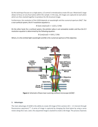
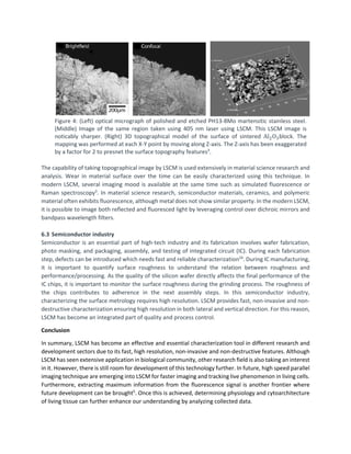
A Report on Laser Scanning Confocal Microscope
Udayan Ghosh, Department of Mechanical Engineering, University of Utah
1. Introduction
Technological advancement in microfabrication, biological and material science requires characterization
in every step. To aid this advancement, laser scanning confocal microscope (LSCM) has emerged as an
invaluable tool for investigation and analysis1–6
. At the right configuration, a LSCM can be used as high
resolution optical microscope with infinite depth of while working as non-contact optical profilometer3
.
After the invention of laser, combining with confocal microscopy, the development of LSCM started and
with the technological advancement and computational power, it emerged as an essential
characterization tool7–9
. In this project report, first, we will highlight the working principle of the laser
scanning confocal microscope (LSCM) in details. Next, we will highlight the advantages and limitations of
this characterization technique comparing with similar characterization tools/methods to get a
comprehensive idea on application. Finally, application of LSCM in different research and technology
development sectors will be discussed.
2. Working principle
The basic principal of laser scanning confocal microscopy originate from the technique patented by Marvin
Minsky in 19557
. In comparison to a conventional microscope, specimen can be investigated as far as the
light can penetrate whereas a confocal microscope scans a single depth layer at a time10
.
The instrument setup schematic of LSCM is presented in Figure 1. A laser beam is focused onto the
specimen. Emitted laser from the laser excitation source passes through a pinhole aperture. This pinhole
aperture is in a conjugated plane (confocal) and there is a second pin hole which sits in front of the
photomultiplier detector. The intensity of the laser can be controlled using neutral density filters too. A
dichromatic mirror is reflects the laser onto the specimen surface and by controlling the movement of this
mirror, the whole specimen is scanned very precisely and quickly1,10
. Tilting of the mirror allows the beam
to raster in both X and Y direction on a defined focal plane. The secondary fluorescence emits from the
scan point and pass back through the dichromatic mirror. This passed beam is focused as a confocal point
at the detector’s pinhole aperture. This pin hole apertures are situated at the intermediate image plane
of the microscope. The purpose of this pinhole is to allow only a small part of the light through to the
detector. A set of filters are used to separate the laser light from the reflected light from the sample.
When a reflected light is being examined, it is passed through a polarizer filter which allows only the laser
light with a different polarization angle from the initial laser light to pass10
. However, during this process
the light may have low intensity. For this reason, a photomultiplier tube is used to amplify the light signal.
The electrical signal from the photomultipliers is then used to create the display image on the computer
monitor. During this process, the detection system constantly samples and process the collected data to
present the image in the computer monitor. The correct order is fixed in the computer so that the display
seem real time projection of the sample.
As this technique focuses on a single plane, a Z-control is introduced to create 3D scan. Motorized Z-stage
allows to focus on any focal plane within the sample. In this way, 2D images are captured at each plane
which are then stacked together to produce the 3D structural image.
Furthermore, the resolution of the LSCM depends on wavelength and the numerical aperture (NA)11
. For
a non-confocal system, the X-Y resolution equation is:
𝑅𝑅 (𝑛𝑛𝑛𝑛𝑛𝑛 𝑐𝑐𝑐𝑐𝑐𝑐𝑐𝑐𝑐𝑐𝑐𝑐𝑐𝑐𝑐𝑐) = 1.22 λ / 2 NA
On the other hand, for a confocal system, the pinhole radius is set somewhat smaller and thus the X-Y
resolution equation is determined by the following equation:
𝑅𝑅 (𝑐𝑐𝑐𝑐𝑐𝑐𝑐𝑐𝑐𝑐𝑐𝑐𝑐𝑐𝑐𝑐) = 0.8 λ / 2 NA
Where, λ is the emitted light wavelength and NA is the numerical aperture of the objective.
Figure 1: Schematic of basic laser scanning confocal microscope (LSCM)1
.
3. Advantages
The main advantage of LSCM is the ability to create 2D image of thin sections (0.5 – 1.5 micron) through
fluorescence specimens1,12
. A series of image is captured by changing the focal plane by using a servo
motor along the Z-axis. Later, this sequential image is stacked to create a 3D image. This process improves
the signal to noise ratio which results in improved contrast and definition. Moreover, this optical
sectioning overcomes any artifacts due to physical sectioning of samples in the traditional microscopy.
LSCM process is non-invasive which allows examining living and fixed biological samples under different
conditions. The capability of creating 3D stacking allows researchers to examine the samples from a
different perspective. Figure 2 presents typical 3D image of several biological specimens by stacking serial
optical sectioning. In the figure 2A, a series of sections of the sunflower pollen grain was combined to
create a realistic view of the exterior surface. In a similar way, mouse’s lung tissue, rat’s brain tissue and
fern root has been scanned. Structural and functional analysis of biological cell and tissue is benefitted
from the 3D volumetric rendering technique of LSCM.
Additionally, in LSCM, magnification can be adjusted by varying scanning area by the laser. This process
does not require changing the objectives like traditional optical microscopy. Adjusting sampling period of
the scanning laser, spatial resolution is altered as necessary. Increasing the zoom factor decreases the
sampling area; hence scanning rate decreases. So, increased number of samples are collected along a
comparable length13,14
. This ensures better spatial resolution and magnification of the output image.
Figure 2: 3D renders of the biological specimen imaged using LSCM1
. A. Exterior surface of the
sunflower pollen grain. B. Lung tissue of the mouse. C. A thick section of rat’s brain. The image was
constructed by stacking 35-40 optical sections. D. Thin section of fern root.
4. Limitation
The limitation of this process lies with any limitation in laser light source. For common laser light source,
there is a limited number of excitation wavelengths over very narrow bands. In comparison, conventional
microscopy uses wider range of excitation wavelength.
Moreover, the laser can be harmful for particular biological samples. The high intensity laser irradiation
can destroy or alter the property of the specimen which can lead to incorrect interpretation of the
investigation.
5. Comparison of LSCM with similar characterization tool:
LSCM has both advantages and drawback in comparison to other characterization tools. However, this
also depends on the application, nature of the specimen, and the scale that we are interested in. LSCM
can be used in material science and characterization by capturing the surface profile. However, this
process is nondestructive in comparison to stylus based profilometry. Similarly, other technique such as
atomic force microscope and optical microscopy can also be used for topographical analysis. Table 1
summarizes some features between LSCM and these similar characterization tools.
Table 1: Comparison between LSCM and other characterization tools15
Characterization
Technique
Resolution Probe
Area
Thickness
range
Key Application Key Feature
Laser Scanning
Confocal
Microscope
(LSCM)
0.3 µm 0.3 µm < 1 µm Independent
layer imaging
Non-invasive
process. No
vacuum
requirement.
Stylus
profilometer
Resolution is
better than 1
Å
Depends
on tip size
Material
characterization
and process
R&D.
Surface profile is
measured using
contact stylus
which can damage
the specimen
Atomic Force
Microscope
(AFM)
One atom 50-100 Å < 1 Å Surface
tribology
Slow process.
Probe tip wear over
time. Non-
destructive process
Optical
Microscopy
Magnification
10-1000
- 0.3 – 0.5
µm
Universal too
for dimensions
> 0.29 µm
Depth of field is
small
6. Application
Although the initial application of LSCM was focused towards biological, biochemical and biomedical
research, it has recently become an effective and essential tool in material science and semiconductor
industry3,5,16,17
. Key application in the respective field is described here:
6.1 Biology
LSCM is widely used in biological research. Advancement in live cell imaging has been brought by
LSCM5,18
. Imaging living tissues is considered as more difficult than imaging fixed sample19
. Extreme care
needs to be taken to preserve the viability of the living cells. Laser power should be kept minimal so that
it cannot harm the sample over multiple scans. For this purpose, pulses for a brief period is applied
while imaging live cells.
In biological research. It is often needed to map the distribution of macro molecules in the tissue. When
different molecules need to be tracked in the same tissue, fluorescence labeling is considered. LSCM
process allows to track all of them simultaneously. However, this process can be complex due to merging
multiple labeling and it is important to be careful during interpreting these images if there are spectral
overlapping2
. Figure 3 represents labelling of the Drosophila embryo and image has been taken using
LSCM.
Figure 3: Single, double and tripple lablleing of a Drosophila embryo from left to right2
.
Moreover, lineage analysis can be performed using LSCM. If there are few cells inside the developing
embryo and labelled as fluorescent probe, development can continue while active subsequent imaging
can be performed using LSCM. This approach has been used to trace the migration of neural crest cells in
the mouse embryo2,20
and cells in sea urchin embryos21
. In addition, physiological parameters such as fluo-
3, calcium green, sodium levels, membrane potential can be characterized using LSCM. However, many
physiological events can be faster than the imaging speed of LSCM. To overcome this challenge, fast
scanning LSCM has been designed which consider acousto-optical scanner instead of point aperture.
6.2 Material science
In traditional microscope for metallurgical investigation purpose, sample preparation is an important step
where samples need to be polished first and then lightly etched to get optical contrast3
. When in focus,
both conventional microscope and the confocal microscope can achieve sharp images but otherwise, the
intensity in the out-of-focus region decreases fast8,22,23
. In the left and middle of the figure 4, it is clearly
visible that the image from a LSCM is noticeably crispy and sharper. In LSCM, the integration of the
motorized Z-stage addresses this concern effectively by taking a series of 2D images at different focal
planes and form a composite image of infinite depth of field. The right image in figure 4, represents a
surface topographical information in 3D after scanning and stacking multiple 2D images.
Figure 4: (Left) optical micrograph of polished and etched PH13-8Mo martensitic stainless steel.
(Middle) Image of the same region taken using 405 nm laser using LSCM. This LSCM image is
noticably sharper. (Right) 3D topographical model of the surface of sintered Al2O3block. The
mapping was performed at each X-Y point by moving along Z-axis. The Z-axis has been exaggerated
by a factor for 2 to presnet the surface topography features3
.
The capability of taking topographical image by LSCM is used extensively in material science research and
analysis. Wear in material surface over the time can be easily characterized using this technique. In
modern LSCM, several imaging mood is available at the same time such as simulated fluorescence or
Raman spectroscopy3
. In material science research, semiconductor materials, ceramics, and polymeric
material often exhibits fluorescence, although metal does not show similar property. In the modern LSCM,
it is possible to image both reflected and fluoresced light by leveraging control over dichroic mirrors and
bandpass wavelength filters.
6.3 Semiconductor industry
Semiconductor is an essential part of high-tech industry and its fabrication involves wafer fabrication,
photo masking, and packaging, assembly, and testing of integrated circuit (IC). During each fabrication
step, defects can be introduced which needs fast and reliable characterization24
. During IC manufacturing,
it is important to quantify surface roughness to understand the relation between roughness and
performance/processing. As the quality of the silicon wafer directly affects the final performance of the
IC chips, it is important to monitor the surface roughness during the grinding process. The roughness of
the chips contributes to adherence in the next assembly steps. In this semiconductor industry,
characterizing the surface metrology requires high resolution. LSCM provides fast, non-invasive and non-
destructive characterization ensuring high resolution in both lateral and vertical direction. For this reason,
LSCM has become an integrated part of quality and process control.
Conclusion
In summary, LSCM has become an effective and essential characterization tool in different research and
development sectors due to its fast, high resolution, non-invasive and non-destructive features. Although
LSCM has seen extensive application in biological community, other research field is also taking an interest
in it. However, there is still room for development of this technology further. In future, high speed parallel
imaging technique are emerging into LSCM for faster imaging and tracking live phenomenon in living cells.
Furthermore, extracting maximum information from the fluorescence signal is another frontier where
future development can be brought5
. Once this is achieved, determining physiology and cytoarchitecture
of living tissue can further enhance our understanding by analyzing collected data.
Reference
1. Claxton, N. S., Fellers, T. J. & Davidson, M. W. LASER SCANNING CONFOCAL MICROSCOPY.
www.aptechnologies.co.uk.
2. Paddock, S. W. What’s new: To boldly glow?. Applications of laser scanning confocal microscopy
in developmental biology. BioEssays 16, 357–365 (1994).
3. HOVIS, D. B. & HEUER, A. H. The use of laser scanning confocal microscopy (LSCM) in materials
science. J. Microsc. 240, 173–180 (2010).
4. Paddock, S. W. Principles and practices of laser scanning confocal microscopy. Applied
Biochemistry and Biotechnology - Part B Molecular Biotechnology vol. 16 127–149 (2000).
5. Confocal Microscopy: Methods and Protocols - Google Books.
https://books.google.com/books?hl=en&lr=&id=IZvWT_X2l1IC&oi=fnd&pg=PR5&dq=Confocal+M
icroscopy+Methods+and+Protocols&ots=Ous91UniF7&sig=c9DTRHtnZEnWyDMrcJ77-
QdZEew#v=onepage&q=Confocal Microscopy Methods and Protocols&f=false.
6. Qian, J. et al. Full-color structured illumination optical sectioning microscopy. Sci. Rep. 5, 1–10
(2015).
7. Minsky, M. Memoir on inventing the confocal scanning microscope. Scanning 10, 128–138
(1988).
8. Hamilton, D. K. & Wilson, T. Three-dimensional surface measurement using the confocal scanning
microscope. Appl. Phys. B Photophysics Laser Chem. 27, 211–213 (1982).
9. Amos, W. B. & White, J. G. How the Confocal Laser Scanning Microscope entered Biological
Research. Biol. Cell 95, 335–342 (2003).
10. What is Confocal Laser Scanning Microscopy? - Bitesize Bio. https://bitesizebio.com/19958/what-
is-confocal-laser-scanning-microscopy/.
11. Bagnell, © C Robert. Chapter 13 Confocal Laser Scanning Microscopy Background for
Understanding CLSM.
12. Sandison, D. R. & Webb, W. W. Background rejection and signal-to-noise optimization in confocal
and alternative fluorescence microscopes. Appl. Opt. 33, 603 (1994).
13. Centonze, V. & Pawley, J. B. Tutorial on practical confocal microscopy and use of the confocal test
specimen. in Handbook of Biological Confocal Microscopy: Third Edition 627–649 (Springer US,
2006). doi:10.1007/978-0-387-45524-2_35.
14. Pawley, J. B. Handbook of biological confocal microscopy: Third edition. Handbook of Biological
Confocal Microscopy: Third Edition (Springer US, 2006). doi:10.1007/978-0-387-45524-2.
15. Madou, M. J. From MEMS to Bio-MEMS and Bio-NEMS: Manufacturing Techniques and
Applications. (CRC Press, 2011).
16. Paddock, S. W. An introduction to confocal imaging. Methods in molecular biology (Clifton, N.J.)
vol. 122 1–34 (1999).
17. Wymer, C. L., Beven, A. F., Boudonck, K. & Lloyd, C. W. Confocal microscopy of plant cells.
Methods in molecular biology (Clifton, N.J.) vol. 122 103–130 (1999).
18. van Roessel, P. & Brand, A. H. Imaging into the future: Visualizing gene expression and protein
interactions with fluorescent proteins. Nature Cell Biology vol. 4 (2002).
19. Pawley, J. The 39 steps: A cautionary tale of quantitative 3-D fluorescence microscopy.
Biotechniques 28, 884–888 (2000).
20. Serbedzija, G. N., Bronner-Fraser, M. & Fraser, S. E. Vital dye analysis of cranial neural crest cell
migration in the mouse embryo. Development 116, (1992).
21. Cameron, R. A., Fraser, S. E., Britten, R. J. & Davidson, E. H. Macromere cell fates during sea
urchin development. Development 113, (1991).
22. Carlsson, K. & Åslund, N. Confocal imaging for 3-D digital microscopy. Appl. Opt. 26, 3232 (1987).
23. Carlsson, K. et al. Three-dimensional microscopy using a confocal laser scanning microscope. Opt.
Lett. 10, 53 (1985).
24. Advantages of Laser Confocal Microscopes for Semiconductor Inspection.
https://www.mfgnewsweb.com/archives/4/54141/Applying-Technology-apr19/Advantages-of-
Laser-Confocal-Microscopes-for-Semiconductor-Inspection.aspx.

Review on laser scanning confocal microscopy

  • 1.
    A Report onLaser Scanning Confocal Microscope Udayan Ghosh, Department of Mechanical Engineering, University of Utah 1. Introduction Technological advancement in microfabrication, biological and material science requires characterization in every step. To aid this advancement, laser scanning confocal microscope (LSCM) has emerged as an invaluable tool for investigation and analysis1–6 . At the right configuration, a LSCM can be used as high resolution optical microscope with infinite depth of while working as non-contact optical profilometer3 . After the invention of laser, combining with confocal microscopy, the development of LSCM started and with the technological advancement and computational power, it emerged as an essential characterization tool7–9 . In this project report, first, we will highlight the working principle of the laser scanning confocal microscope (LSCM) in details. Next, we will highlight the advantages and limitations of this characterization technique comparing with similar characterization tools/methods to get a comprehensive idea on application. Finally, application of LSCM in different research and technology development sectors will be discussed. 2. Working principle The basic principal of laser scanning confocal microscopy originate from the technique patented by Marvin Minsky in 19557 . In comparison to a conventional microscope, specimen can be investigated as far as the light can penetrate whereas a confocal microscope scans a single depth layer at a time10 . The instrument setup schematic of LSCM is presented in Figure 1. A laser beam is focused onto the specimen. Emitted laser from the laser excitation source passes through a pinhole aperture. This pinhole aperture is in a conjugated plane (confocal) and there is a second pin hole which sits in front of the photomultiplier detector. The intensity of the laser can be controlled using neutral density filters too. A dichromatic mirror is reflects the laser onto the specimen surface and by controlling the movement of this mirror, the whole specimen is scanned very precisely and quickly1,10 . Tilting of the mirror allows the beam to raster in both X and Y direction on a defined focal plane. The secondary fluorescence emits from the scan point and pass back through the dichromatic mirror. This passed beam is focused as a confocal point at the detector’s pinhole aperture. This pin hole apertures are situated at the intermediate image plane of the microscope. The purpose of this pinhole is to allow only a small part of the light through to the detector. A set of filters are used to separate the laser light from the reflected light from the sample. When a reflected light is being examined, it is passed through a polarizer filter which allows only the laser light with a different polarization angle from the initial laser light to pass10 . However, during this process the light may have low intensity. For this reason, a photomultiplier tube is used to amplify the light signal. The electrical signal from the photomultipliers is then used to create the display image on the computer monitor. During this process, the detection system constantly samples and process the collected data to present the image in the computer monitor. The correct order is fixed in the computer so that the display seem real time projection of the sample.
  • 2.
    As this techniquefocuses on a single plane, a Z-control is introduced to create 3D scan. Motorized Z-stage allows to focus on any focal plane within the sample. In this way, 2D images are captured at each plane which are then stacked together to produce the 3D structural image. Furthermore, the resolution of the LSCM depends on wavelength and the numerical aperture (NA)11 . For a non-confocal system, the X-Y resolution equation is: 𝑅𝑅 (𝑛𝑛𝑛𝑛𝑛𝑛 𝑐𝑐𝑐𝑐𝑐𝑐𝑐𝑐𝑐𝑐𝑐𝑐𝑐𝑐𝑐𝑐) = 1.22 λ / 2 NA On the other hand, for a confocal system, the pinhole radius is set somewhat smaller and thus the X-Y resolution equation is determined by the following equation: 𝑅𝑅 (𝑐𝑐𝑐𝑐𝑐𝑐𝑐𝑐𝑐𝑐𝑐𝑐𝑐𝑐𝑐𝑐) = 0.8 λ / 2 NA Where, λ is the emitted light wavelength and NA is the numerical aperture of the objective. Figure 1: Schematic of basic laser scanning confocal microscope (LSCM)1 . 3. Advantages The main advantage of LSCM is the ability to create 2D image of thin sections (0.5 – 1.5 micron) through fluorescence specimens1,12 . A series of image is captured by changing the focal plane by using a servo motor along the Z-axis. Later, this sequential image is stacked to create a 3D image. This process improves
  • 3.
    the signal tonoise ratio which results in improved contrast and definition. Moreover, this optical sectioning overcomes any artifacts due to physical sectioning of samples in the traditional microscopy. LSCM process is non-invasive which allows examining living and fixed biological samples under different conditions. The capability of creating 3D stacking allows researchers to examine the samples from a different perspective. Figure 2 presents typical 3D image of several biological specimens by stacking serial optical sectioning. In the figure 2A, a series of sections of the sunflower pollen grain was combined to create a realistic view of the exterior surface. In a similar way, mouse’s lung tissue, rat’s brain tissue and fern root has been scanned. Structural and functional analysis of biological cell and tissue is benefitted from the 3D volumetric rendering technique of LSCM. Additionally, in LSCM, magnification can be adjusted by varying scanning area by the laser. This process does not require changing the objectives like traditional optical microscopy. Adjusting sampling period of the scanning laser, spatial resolution is altered as necessary. Increasing the zoom factor decreases the sampling area; hence scanning rate decreases. So, increased number of samples are collected along a comparable length13,14 . This ensures better spatial resolution and magnification of the output image. Figure 2: 3D renders of the biological specimen imaged using LSCM1 . A. Exterior surface of the sunflower pollen grain. B. Lung tissue of the mouse. C. A thick section of rat’s brain. The image was constructed by stacking 35-40 optical sections. D. Thin section of fern root.
  • 4.
    4. Limitation The limitationof this process lies with any limitation in laser light source. For common laser light source, there is a limited number of excitation wavelengths over very narrow bands. In comparison, conventional microscopy uses wider range of excitation wavelength. Moreover, the laser can be harmful for particular biological samples. The high intensity laser irradiation can destroy or alter the property of the specimen which can lead to incorrect interpretation of the investigation. 5. Comparison of LSCM with similar characterization tool: LSCM has both advantages and drawback in comparison to other characterization tools. However, this also depends on the application, nature of the specimen, and the scale that we are interested in. LSCM can be used in material science and characterization by capturing the surface profile. However, this process is nondestructive in comparison to stylus based profilometry. Similarly, other technique such as atomic force microscope and optical microscopy can also be used for topographical analysis. Table 1 summarizes some features between LSCM and these similar characterization tools. Table 1: Comparison between LSCM and other characterization tools15 Characterization Technique Resolution Probe Area Thickness range Key Application Key Feature Laser Scanning Confocal Microscope (LSCM) 0.3 µm 0.3 µm < 1 µm Independent layer imaging Non-invasive process. No vacuum requirement. Stylus profilometer Resolution is better than 1 Å Depends on tip size Material characterization and process R&D. Surface profile is measured using contact stylus which can damage the specimen Atomic Force Microscope (AFM) One atom 50-100 Å < 1 Å Surface tribology Slow process. Probe tip wear over time. Non- destructive process Optical Microscopy Magnification 10-1000 - 0.3 – 0.5 µm Universal too for dimensions > 0.29 µm Depth of field is small 6. Application Although the initial application of LSCM was focused towards biological, biochemical and biomedical research, it has recently become an effective and essential tool in material science and semiconductor industry3,5,16,17 . Key application in the respective field is described here:
  • 5.
    6.1 Biology LSCM iswidely used in biological research. Advancement in live cell imaging has been brought by LSCM5,18 . Imaging living tissues is considered as more difficult than imaging fixed sample19 . Extreme care needs to be taken to preserve the viability of the living cells. Laser power should be kept minimal so that it cannot harm the sample over multiple scans. For this purpose, pulses for a brief period is applied while imaging live cells. In biological research. It is often needed to map the distribution of macro molecules in the tissue. When different molecules need to be tracked in the same tissue, fluorescence labeling is considered. LSCM process allows to track all of them simultaneously. However, this process can be complex due to merging multiple labeling and it is important to be careful during interpreting these images if there are spectral overlapping2 . Figure 3 represents labelling of the Drosophila embryo and image has been taken using LSCM. Figure 3: Single, double and tripple lablleing of a Drosophila embryo from left to right2 . Moreover, lineage analysis can be performed using LSCM. If there are few cells inside the developing embryo and labelled as fluorescent probe, development can continue while active subsequent imaging can be performed using LSCM. This approach has been used to trace the migration of neural crest cells in the mouse embryo2,20 and cells in sea urchin embryos21 . In addition, physiological parameters such as fluo- 3, calcium green, sodium levels, membrane potential can be characterized using LSCM. However, many physiological events can be faster than the imaging speed of LSCM. To overcome this challenge, fast scanning LSCM has been designed which consider acousto-optical scanner instead of point aperture. 6.2 Material science In traditional microscope for metallurgical investigation purpose, sample preparation is an important step where samples need to be polished first and then lightly etched to get optical contrast3 . When in focus, both conventional microscope and the confocal microscope can achieve sharp images but otherwise, the intensity in the out-of-focus region decreases fast8,22,23 . In the left and middle of the figure 4, it is clearly visible that the image from a LSCM is noticeably crispy and sharper. In LSCM, the integration of the motorized Z-stage addresses this concern effectively by taking a series of 2D images at different focal planes and form a composite image of infinite depth of field. The right image in figure 4, represents a surface topographical information in 3D after scanning and stacking multiple 2D images.
  • 6.
    Figure 4: (Left)optical micrograph of polished and etched PH13-8Mo martensitic stainless steel. (Middle) Image of the same region taken using 405 nm laser using LSCM. This LSCM image is noticably sharper. (Right) 3D topographical model of the surface of sintered Al2O3block. The mapping was performed at each X-Y point by moving along Z-axis. The Z-axis has been exaggerated by a factor for 2 to presnet the surface topography features3 . The capability of taking topographical image by LSCM is used extensively in material science research and analysis. Wear in material surface over the time can be easily characterized using this technique. In modern LSCM, several imaging mood is available at the same time such as simulated fluorescence or Raman spectroscopy3 . In material science research, semiconductor materials, ceramics, and polymeric material often exhibits fluorescence, although metal does not show similar property. In the modern LSCM, it is possible to image both reflected and fluoresced light by leveraging control over dichroic mirrors and bandpass wavelength filters. 6.3 Semiconductor industry Semiconductor is an essential part of high-tech industry and its fabrication involves wafer fabrication, photo masking, and packaging, assembly, and testing of integrated circuit (IC). During each fabrication step, defects can be introduced which needs fast and reliable characterization24 . During IC manufacturing, it is important to quantify surface roughness to understand the relation between roughness and performance/processing. As the quality of the silicon wafer directly affects the final performance of the IC chips, it is important to monitor the surface roughness during the grinding process. The roughness of the chips contributes to adherence in the next assembly steps. In this semiconductor industry, characterizing the surface metrology requires high resolution. LSCM provides fast, non-invasive and non- destructive characterization ensuring high resolution in both lateral and vertical direction. For this reason, LSCM has become an integrated part of quality and process control. Conclusion In summary, LSCM has become an effective and essential characterization tool in different research and development sectors due to its fast, high resolution, non-invasive and non-destructive features. Although LSCM has seen extensive application in biological community, other research field is also taking an interest in it. However, there is still room for development of this technology further. In future, high speed parallel imaging technique are emerging into LSCM for faster imaging and tracking live phenomenon in living cells. Furthermore, extracting maximum information from the fluorescence signal is another frontier where future development can be brought5 . Once this is achieved, determining physiology and cytoarchitecture of living tissue can further enhance our understanding by analyzing collected data.
  • 7.
    Reference 1. Claxton, N.S., Fellers, T. J. & Davidson, M. W. LASER SCANNING CONFOCAL MICROSCOPY. www.aptechnologies.co.uk. 2. Paddock, S. W. What’s new: To boldly glow?. Applications of laser scanning confocal microscopy in developmental biology. BioEssays 16, 357–365 (1994). 3. HOVIS, D. B. & HEUER, A. H. The use of laser scanning confocal microscopy (LSCM) in materials science. J. Microsc. 240, 173–180 (2010). 4. Paddock, S. W. Principles and practices of laser scanning confocal microscopy. Applied Biochemistry and Biotechnology - Part B Molecular Biotechnology vol. 16 127–149 (2000). 5. Confocal Microscopy: Methods and Protocols - Google Books. https://books.google.com/books?hl=en&lr=&id=IZvWT_X2l1IC&oi=fnd&pg=PR5&dq=Confocal+M icroscopy+Methods+and+Protocols&ots=Ous91UniF7&sig=c9DTRHtnZEnWyDMrcJ77- QdZEew#v=onepage&q=Confocal Microscopy Methods and Protocols&f=false. 6. Qian, J. et al. Full-color structured illumination optical sectioning microscopy. Sci. Rep. 5, 1–10 (2015). 7. Minsky, M. Memoir on inventing the confocal scanning microscope. Scanning 10, 128–138 (1988). 8. Hamilton, D. K. & Wilson, T. Three-dimensional surface measurement using the confocal scanning microscope. Appl. Phys. B Photophysics Laser Chem. 27, 211–213 (1982). 9. Amos, W. B. & White, J. G. How the Confocal Laser Scanning Microscope entered Biological Research. Biol. Cell 95, 335–342 (2003). 10. What is Confocal Laser Scanning Microscopy? - Bitesize Bio. https://bitesizebio.com/19958/what- is-confocal-laser-scanning-microscopy/. 11. Bagnell, © C Robert. Chapter 13 Confocal Laser Scanning Microscopy Background for Understanding CLSM. 12. Sandison, D. R. & Webb, W. W. Background rejection and signal-to-noise optimization in confocal and alternative fluorescence microscopes. Appl. Opt. 33, 603 (1994). 13. Centonze, V. & Pawley, J. B. Tutorial on practical confocal microscopy and use of the confocal test specimen. in Handbook of Biological Confocal Microscopy: Third Edition 627–649 (Springer US, 2006). doi:10.1007/978-0-387-45524-2_35. 14. Pawley, J. B. Handbook of biological confocal microscopy: Third edition. Handbook of Biological Confocal Microscopy: Third Edition (Springer US, 2006). doi:10.1007/978-0-387-45524-2. 15. Madou, M. J. From MEMS to Bio-MEMS and Bio-NEMS: Manufacturing Techniques and Applications. (CRC Press, 2011). 16. Paddock, S. W. An introduction to confocal imaging. Methods in molecular biology (Clifton, N.J.) vol. 122 1–34 (1999). 17. Wymer, C. L., Beven, A. F., Boudonck, K. & Lloyd, C. W. Confocal microscopy of plant cells. Methods in molecular biology (Clifton, N.J.) vol. 122 103–130 (1999).
  • 8.
    18. van Roessel,P. & Brand, A. H. Imaging into the future: Visualizing gene expression and protein interactions with fluorescent proteins. Nature Cell Biology vol. 4 (2002). 19. Pawley, J. The 39 steps: A cautionary tale of quantitative 3-D fluorescence microscopy. Biotechniques 28, 884–888 (2000). 20. Serbedzija, G. N., Bronner-Fraser, M. & Fraser, S. E. Vital dye analysis of cranial neural crest cell migration in the mouse embryo. Development 116, (1992). 21. Cameron, R. A., Fraser, S. E., Britten, R. J. & Davidson, E. H. Macromere cell fates during sea urchin development. Development 113, (1991). 22. Carlsson, K. & Åslund, N. Confocal imaging for 3-D digital microscopy. Appl. Opt. 26, 3232 (1987). 23. Carlsson, K. et al. Three-dimensional microscopy using a confocal laser scanning microscope. Opt. Lett. 10, 53 (1985). 24. Advantages of Laser Confocal Microscopes for Semiconductor Inspection. https://www.mfgnewsweb.com/archives/4/54141/Applying-Technology-apr19/Advantages-of- Laser-Confocal-Microscopes-for-Semiconductor-Inspection.aspx.