Download to read offline


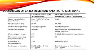

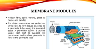
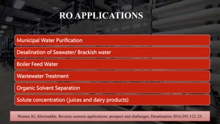


This document provides an overview of reverse osmosis (RO) membrane technology. RO uses pressure to drive water through a semi-permeable membrane, allowing water molecules to pass while retaining dissolved ions and other contaminants. The document discusses RO membrane fabrication, limitations of early cellulose membranes that were addressed by thin-film composite polyamide membranes, membrane module designs, applications of RO including desalination and wastewater treatment, factors that influence membrane selectivity, and challenges of membrane fouling and various mitigation strategies.