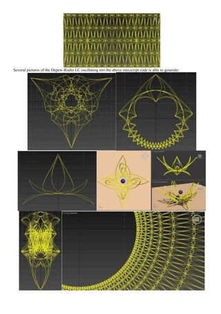
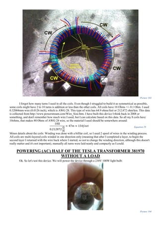
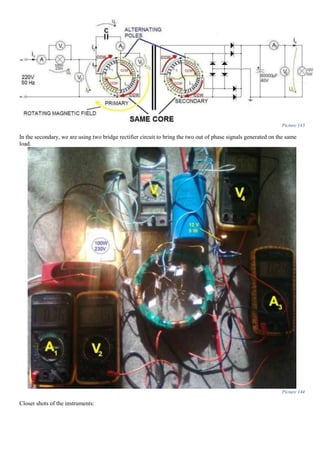
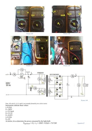
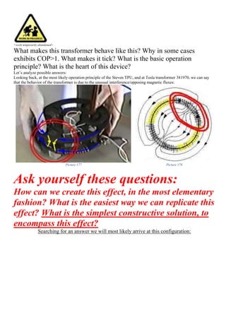
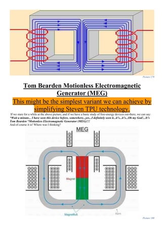
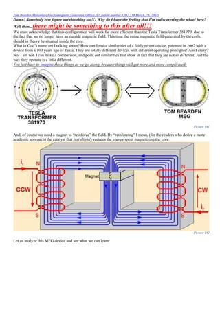
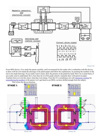
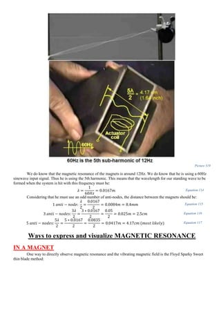
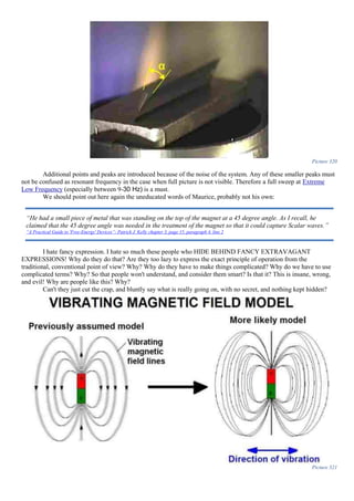
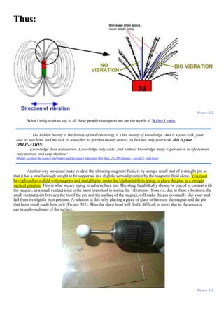
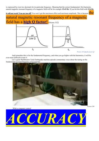
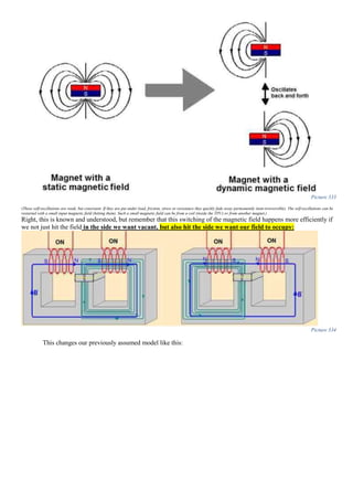
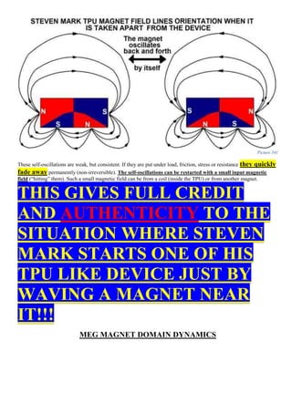
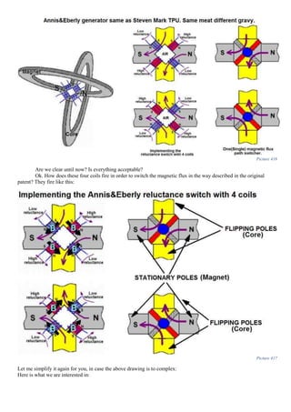
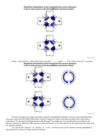
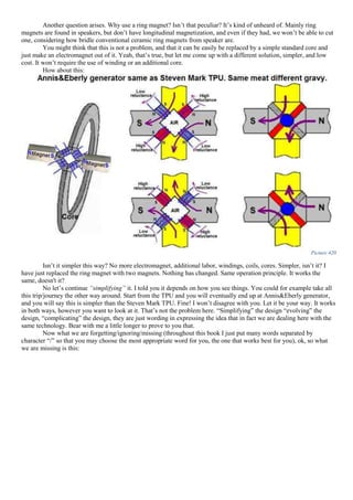
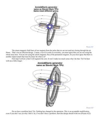
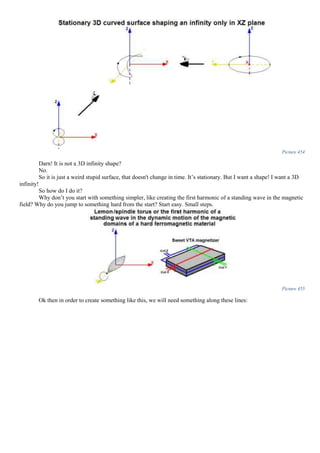
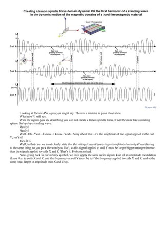
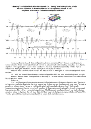
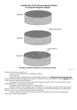
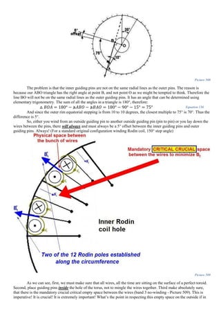
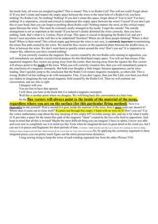
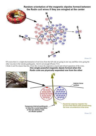
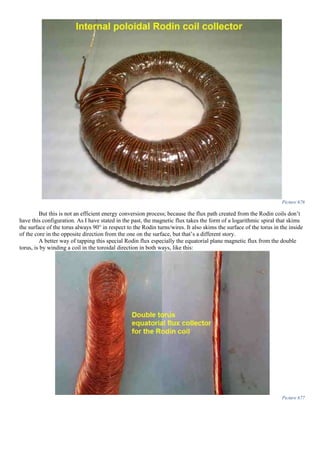
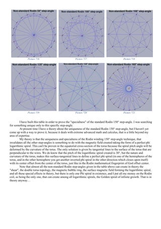
The document is a comprehensive technical exploration of various energy generation technologies, focusing on the Steven Mark Toroidal Power Unit (TPU), Motionless Electromagnetic Generator (MEG), and other related inventions. It covers the construction, operation, and theoretical foundations of these devices, discussing concepts such as the coefficient of performance, magnetic fields, and the Rodin coil. Additionally, it includes insights, experimental procedures, and suggestions for improvements while emphasizing the complexity of the subject matter and the need for further study.
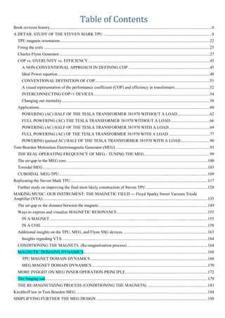


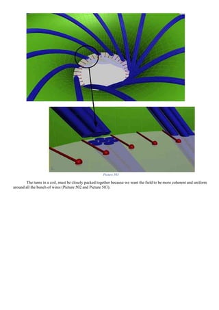
![I quote:
“The coefficient of performance (COP) […] “
Ok so now we know that COP is just performance. Let’s use that term. Therefore we have 3 terms: “Overunity”,
“Efficiency” and “Performance”.
Overunity = variable A
Efficiency = variable B
Performance = variable C
We do know that “Overunity” is the same as “Efficiency” and both are different from “Performance”.
Therefore (A=B) ≠C
(A=B)<>C
Let’s now take the huge and last piece of the puzzle in trying to understand what Performance is:
Ok. Forget the rest of things he says for a while, and let’s stick with the above sentence. At first glance, what do
we see? We see that in parenthesis he still has used the magic word “total” as in “total useful output”. OK? Ok!
Then he says “divided by”, ok so it’s still a ratio, NOTHING DIFFERENT UNTIL NOW, BUT HERE
IT COMES: “ENERGY INPUT BY THE OPERATOR ONLY”. What the hell is “Energy input by the operator only”?
Honestly for now, let’s play dumb and not have any idea of what he is talking about, but what I DO KNOW IS THAT
THE MAGIC WORD “TOTAL” has gone!
HE IS NOT USING A TOTAL IN THE
DENOMINATOR!!!
Let’s try to understand what this alien concept of “energy input by the operator only means”.
Let’s quote him again:
It’s a little tricky but let’s figure this together. Ok? If I’m wrong feel free to correct me. First of all we do see
that in order to state his total output power he first states the efficiency of his system, since:
𝐸𝑓𝑓𝑖𝑐𝑖𝑒𝑛𝑐𝑦 =
𝑡𝑜𝑡𝑎𝑙 𝑂𝑈𝑇
𝑡𝑜𝑡𝑎𝑙 𝐼𝑁
⇒ 𝑇ℎ𝑒𝑟𝑒𝑓𝑜𝑟𝑒 ⇒ 𝑇𝑜𝑡𝑎𝑙 𝑂𝑈𝑇 = (𝑇𝑜𝑡𝑎𝑙 𝐼𝑁 ∗ 𝐸𝑓𝑓𝑖𝑐𝑖𝑒𝑛𝑐𝑦) Equation 1
Are we good until now? Good.
Now what he is doing he is separating the INPUT POWER of
his system into two separate entities:
1. “[…] the operator only has to input, 10 joules […]”
2. “[…] active environment freely inputs 90 joules […]”
Interesting, so he differentiated the total input power of 100 joules into two SEPARATED DISTINCT
ENTITIES. The “Operator” (me or you) and the “Environment” (air, sun-rays, wind, water, ether, vacuum etc.).
His Total output is 50 joules.
Therefore efficiency is:
50
100
=
1
2
⇒ 𝐸𝑓𝑓𝑖𝑐𝑖𝑒𝑛𝑐𝑦 = 0.5 ∗ 100 = 50% Equation 2
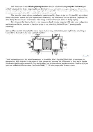
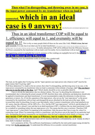
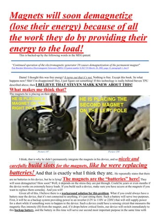
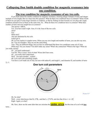
“The coefficient of performance (COP) of a motor or system may be defined as (total useful output) divided by
(ENERGY INPUT BY THE OPERATOR ONLY).”
Tom Bearden letter to John date: Mon, 25 Feb 2002 01:07:52 -0600
“If the operator only has to input, say, 10 joules of energy and the active environment freely inputs 90 joules of
energy, then the total input is 100 joules. Now suppose that the system has 50% efficiency; i.e., it wastes or "loses"
half the energy before it dissipates the rest of it in the load to do useful work. In that case the system outputs 50
joules of work for a total input of 100 joules, but with the operator only inputting 10 of those 100 input joules. So
this system has an efficiency of 50% but a COP =5.0.”
Tom Bearden letter to John date: Mon, 25 Feb 2002 01:07:52 -0600](https://image.slidesharecdn.com/researchinsolidstatefreeenergygeneratorsver7-5-22-130606180846-phpapp02/85/Research-in-solid-state-free-energy-generators-ver-7-5-22-46-320.jpg)
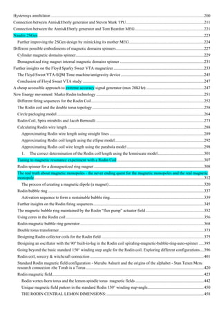
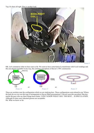
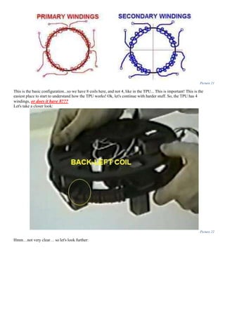
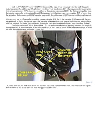
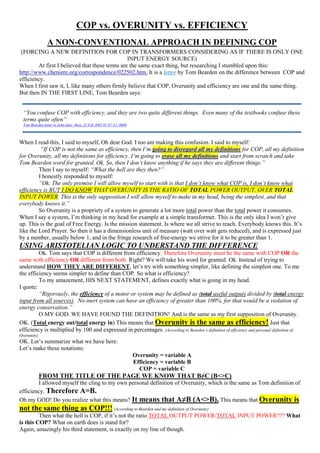
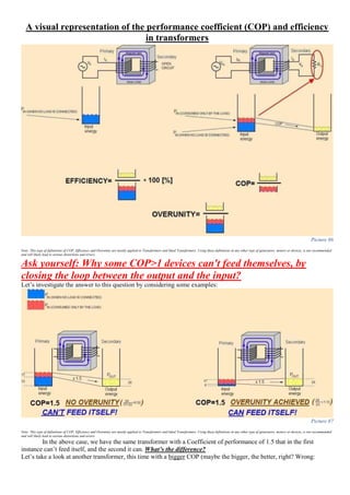
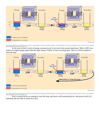
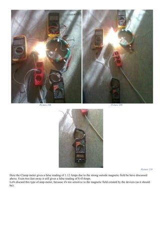
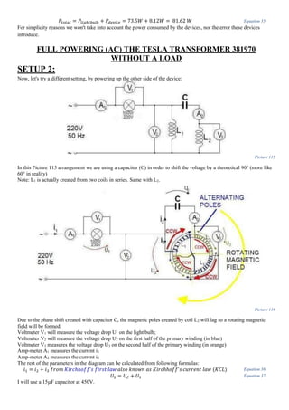
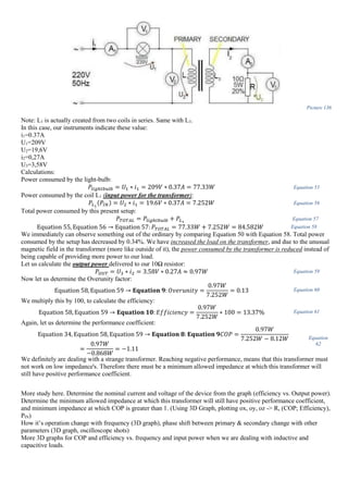
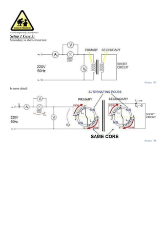
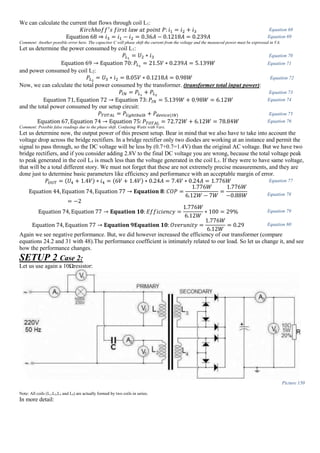
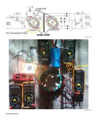
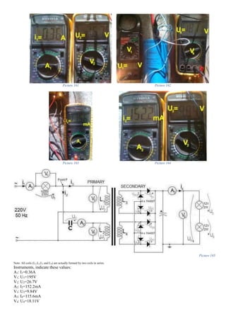
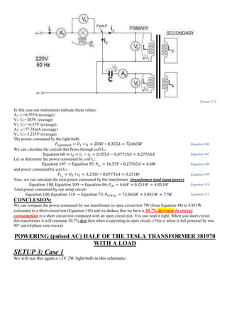
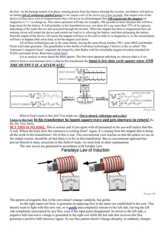
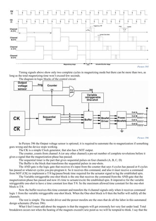
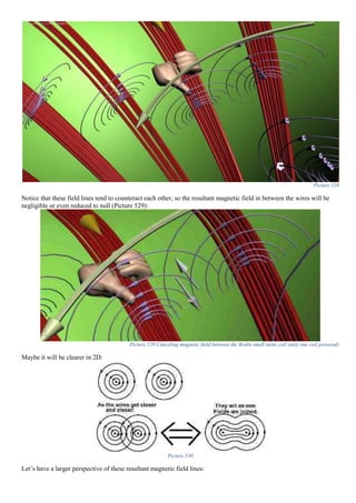
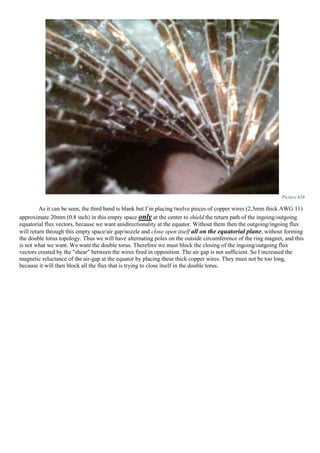
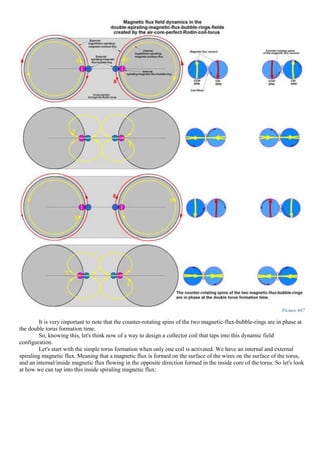
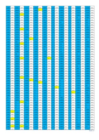
![Picture 83
In this first case, we have a regular transformer with its primary winding connected to an alternating current (AC) power
source. The secondary winding is not connected to anything, it has no load (R=infinite)
We can calculate the power consumed by the transformer in this open-circuit test (PIN), which is:
𝑃𝐼𝑁(𝑁𝑂 𝐿𝑂𝐴𝐷) = 𝑉𝑃 𝑥 𝐼 𝑃 Equation 4
But, when we connect a load that input power changes:
Picture 84
In this case, with an output load, we calculate:
𝑃𝐼𝑁(𝑊𝐼𝑇𝐻 𝐿𝑂𝐴𝐷) = 𝑉𝑃𝐿 ∗ 𝐼 𝑃𝐿 Equation 5
𝑃𝐼𝑁 (𝐶𝑂𝑁𝑆𝑈𝑀𝐸𝐷 𝑂𝑁𝐿𝑌 𝐵𝑌 𝑇𝐻𝐸 𝐿𝑂𝐴𝐷) = 𝑃𝐼𝑁 (𝑊𝐼𝑇𝐻 𝐿𝑂𝐴𝐷) − 𝑃𝐼𝑁 (𝑁𝑂 𝐿𝑂𝐴𝐷) Equation 6
𝑃𝑂𝑈𝑇 = 𝑉𝑆 ∗ 𝐼𝑆 Equation 7
And what we are after are these ratios:
𝑪𝒐𝒆𝒇𝒇𝒊𝒄𝒊𝒆𝒏𝒕 𝒐𝒇 𝒑𝒆𝒓𝒇𝒐𝒓𝒎𝒂𝒏𝒄𝒆(𝑪𝑶𝑷) =
𝑷 𝑶𝑼𝑻
𝑷 𝑰𝑵 (𝑾𝑰𝑻𝑯 𝑳𝑶𝑨𝑫) − 𝑷 𝑰𝑵 (𝑵𝑶 𝑳𝑶𝑨𝑫)
=
𝑷 𝑶𝑼𝑻
𝑷 𝑰𝑵 (𝑪𝑶𝑵𝑺𝑼𝑴𝑬𝑫 𝑶𝑵𝑳𝒀 𝑩𝒀 𝑻𝑯𝑬 𝑳𝑶𝑨𝑫)
Equation 8
𝑶𝒗𝒆𝒓𝒖𝒏𝒊𝒕𝒚 =
𝑷 𝑶𝑼𝑻
𝑷 𝑰𝑵 (𝑾𝑰𝑻𝑯 𝑳𝑶𝑨𝑫)
[𝒏𝒐 𝒖𝒏𝒊𝒕 𝒐𝒇 𝒎𝒆𝒂𝒔𝒖𝒓𝒆] Equation 9
𝑬𝒇𝒇𝒊𝒄𝒊𝒆𝒏𝒄𝒚 =
𝑷 𝑶𝑼𝑻
𝑷 𝑰𝑵 (𝑾𝑰𝑻𝑯 𝑳𝑶𝑨𝑫)
∗ 𝟏𝟎𝟎 [%] Equation 10
This seems like a somewhat "brutal" way to put it, but we now see what a big difference there is between these
parameters.](https://image.slidesharecdn.com/researchinsolidstatefreeenergygeneratorsver7-5-22-130606180846-phpapp02/85/Research-in-solid-state-free-energy-generators-ver-7-5-22-50-320.jpg)
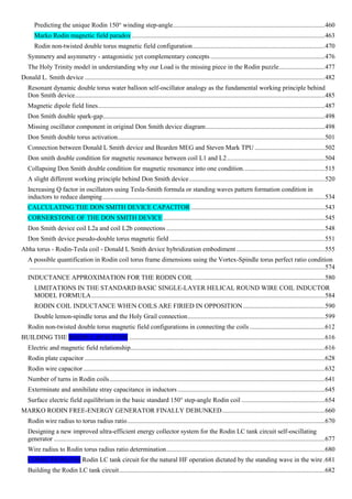
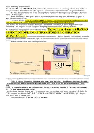
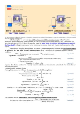
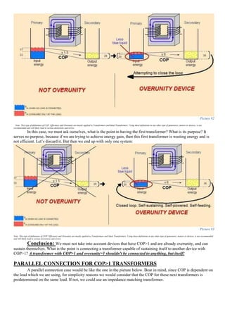
![CONVENTIONAL DEFINITION OF COP
(ONLY APPLIES WHEN WE HAVE MULTIPLE INPUT ENERGY SOURCES)
Picture 85
I hope it’s clear now that the conventional definition only applies when we have an intersection of two special
cases. Again I’m speaking only in regards to transformers. I don’t care about other types of generators, batteries or other
free-energy stuff. I’m only speaking from the limited view point of transformers. So again, going back to this
conventional understanding of COP. It only applies in a special unique case. No! No...Wait there’s more! When we
have two unique special rare cases both of them at once!
First unique special rare case is when we have an additional input power supply. But Most of
transformers on the face of the planet are working
having only ONE POWER SUPPLY! But this is how conventional
COP is defined. We MUST have an additional input power source that provides for the extra energy we see at the
output!
Second unique special rare case that must occur at the same time with the first one, with makes this whole case
more rare than rare, is when we are unable to measure the additional power that this second input is
providing, or it is ambiguous. You see now why we need another approach in defining COP?
The Conventional definition of COP will now be:
𝐶𝑜𝑛𝑣𝑒𝑛𝑡𝑖𝑜𝑛𝑎𝑙 𝐶𝑂𝑃 =
𝑇𝑜𝑡𝑎𝑙 𝑜𝑢𝑡𝑝𝑢𝑡 𝑝𝑜𝑤𝑒𝑟
𝑈𝑠𝑒𝑟 𝑖𝑛𝑝𝑢𝑡 𝑝𝑜𝑤𝑒𝑟
=
𝑉𝑆 ∗ 𝐼𝑆
𝑉𝑈𝑆𝐸𝑅 ∗ 𝐼 𝑈𝑆𝐸𝑅
Equation 11
This will mean that what we will normally be calculating as efficiency of a transformer, and come up with
more than 100% efficiency, actually we have calculated COP. Of course we wouldn't realize that, when
this additional input power source is hiding or is not visible or is not very apparent. So for
all practical reasons we will be tempted to say that we have efficiency over 100%. This is what really Tom Bearden
meant in his letter when he said we shouldn’t confuse COP with efficiency!
Now if we are indeed able to measure the power that this additional input is providing, then things are more
different. We now have two cases, when we have efficiency below and above 100%.
Now the Efficiency will become:
𝐸𝑓𝑓𝑖𝑐𝑖𝑒𝑛𝑐𝑦 =
𝑇𝑜𝑡𝑎𝑙 𝑜𝑢𝑡𝑝𝑢𝑡 𝑝𝑜𝑤𝑒𝑟
𝑇𝑜𝑡𝑎𝑙 𝑖𝑛𝑝𝑢𝑡 𝑝𝑜𝑤𝑒𝑟 𝑓𝑟𝑜𝑚 𝑎𝑙𝑙 𝑠𝑜𝑢𝑟𝑐𝑒𝑠
∗ 100[%]
=
𝑉𝑆 ∗ 𝐼𝑆
𝑉𝑈𝑆𝐸𝑅 ∗ 𝐼 𝑈𝑆𝐸𝑅 + 𝑉𝐴𝐷𝐷𝐼𝑇𝐼𝑂𝑁𝐴𝐿 ∗ 𝐼𝐴𝐷𝐷𝐼𝑇𝐼𝑂𝑁𝐴𝐿
∗ 100[%]
Equation 12
Which can be below 100% or above, case when we say we have achieved overunity.](https://image.slidesharecdn.com/researchinsolidstatefreeenergygeneratorsver7-5-22-130606180846-phpapp02/85/Research-in-solid-state-free-energy-generators-ver-7-5-22-51-320.jpg)
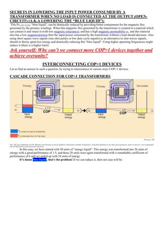
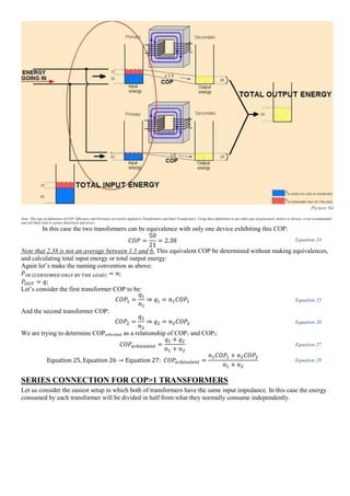
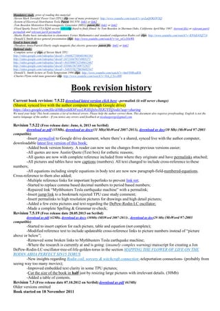
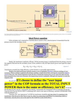
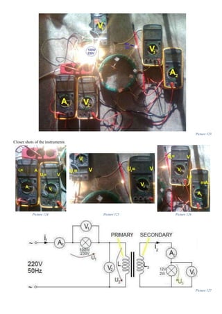
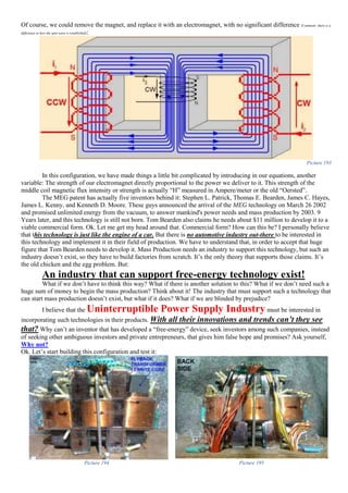
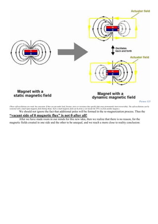
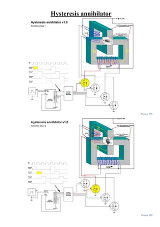
![I believe that we don't have to gain more, but quite the reverse! WE HAVE TO SPEND LESS! And that is the key to
over unity! We don't have to expect to gain more energy at the output! But in fact we must look at the input! That's
where the magic happens. That is where we have to pay attention.
Picture 97
Reaching over unity not by gaining more energy at
the output, but by spending less energy at the input
(a.k.a “blue liquid”)!!!
Yeah, but you still have an energy gain, where does that energy come from? From the magnetic field produced by
permanent magnets. If you have a magnetic field already in place running through a core, then in theory you should
spend less energy building the same magnetic flux, which would have taken a lot more energy to create if you didn't use
a permanent magnet (inductance gain). But in theory, this energy gain from the magnet is so small and insignificant that
you can't use it for anything! You can't do anything with it! Or can you?
Yes you can, if you have a near 100% efficient transformer, you could raise its performance above the 100% mark and
pass the over unity barrier by using this trick! That is again, in theory. That's how I think the TPU really works…in
theory
To back these above words I’m going to use a famous quote:
I don’t believe it’s a very comprehensive sentence, so let me explain what to above quote speaks about:
It speaks about an OVERUNITY SECRET:
■ First step: You don’t energize the input primary side of a transformer with a normal, conventional
approach with power from a power line, you let a permanent magnet energize it. Yeah, but the magnetic
field of a magnet is static. That is correct, BUT you could make the magnetic field of a magnet be
dynamic.
■ Then the second and final step is to make sure that the energy spent dynamising(make more dynamic) the
magnet field by exiting and kicking it, is lower than the energy provided at the output by the magnet.
“[...] with continuous flux paths the static flux from the permanent magnet or magnets is useless. However,
if the static flux of the permanent magnet confined to the flux paths were modified to be time varying it
would have utility for electromagnetic induction devices for power conversion like transformers and power
inverters”
(Charles Joe Flynn, US Patent 6.246.561 B1, Jun. 12, 2001, page 21, line 33)](https://image.slidesharecdn.com/researchinsolidstatefreeenergygeneratorsver7-5-22-130606180846-phpapp02/85/Research-in-solid-state-free-energy-generators-ver-7-5-22-59-320.jpg)
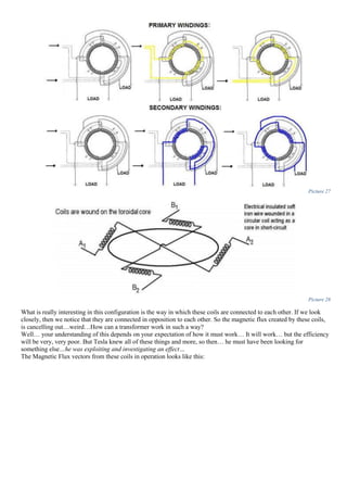
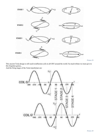
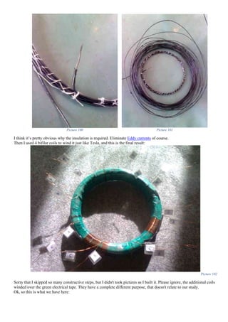
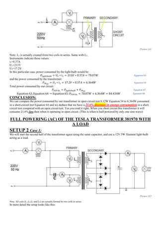
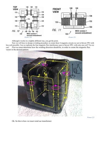
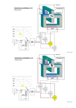
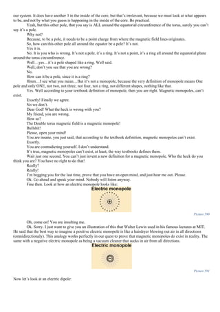
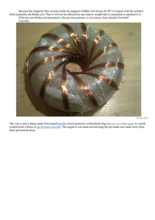
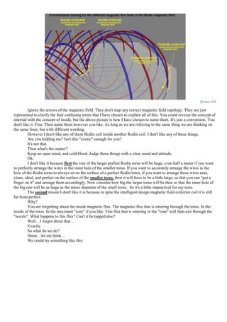
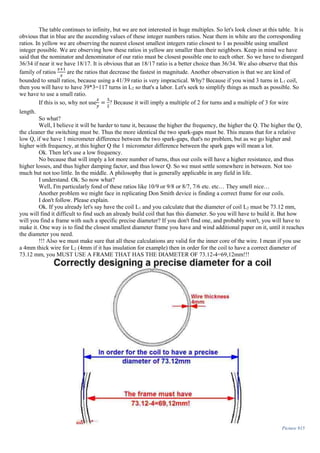
![Applications
Ok. Let's put some of the things we've learn into practice. Let's start with the first analyzed system, the Tesla
Transformer, patent nr. 381,970
The first practical consideration is the core:
Picture 98
And what is made of:
Picture 99
Let’s quote Tesla:
So then, insulated soft iron wire...
I will insulate the wire with electrical tape, and achieve the beehives shape of the core described above, using ordinary
sewing wire:
“I use a core, A, which is close upon itself [...] I make it of thin strips, plates, or wires of soft
iron electrically insulated as far as practicable.”
Nikola Tesla US patent 381970, page 2, line 52](https://image.slidesharecdn.com/researchinsolidstatefreeenergygeneratorsver7-5-22-130606180846-phpapp02/85/Research-in-solid-state-free-energy-generators-ver-7-5-22-60-320.jpg)


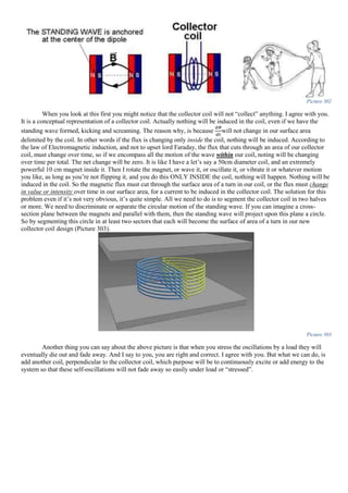
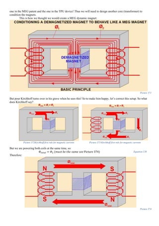
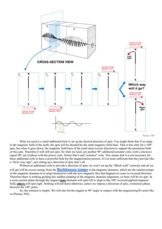
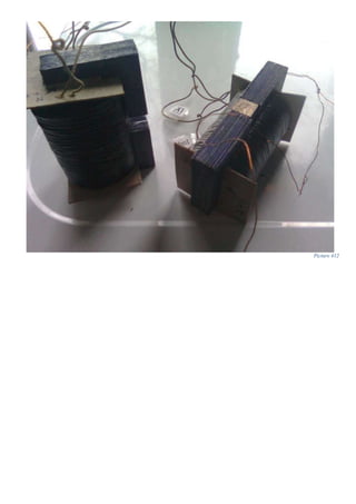
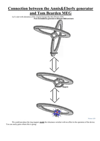
![Now, if we study the patent carefully, we will understand that in this device, and probably in the Steven TPU
also, that in fact the magnet serves not as the “helper” or “catalyst” as we have thought, but is
actually the only “person” who works in this device. The only true “worker”. The magnet is the one that is
doing all the labor! The input coils, just “excite” the magnet, or “dynamising” it, or “KICK” it, in order to
make the static magnetic field of the magnet, a dynamic field. We can actually say that THE
MAGNET is really powering the device (MEG & TPU & Flynn alike) and the input coils (a.k.a.
“actuators”) are just there to just kick the magnet in the butt, so that it’s field won’t become static as it normally want to
be.
This stated in the patent:
An analogy to this, is that the magnet is you at work, doing all the hard labor. The input coils are your boss, that
kicks you in the butt so that you always keep going and not to take a break for a coffee or something. Another analogy
is that the magnet is your heart, and the small input signal, is your heart beat, is the divine small input source (The Boss)
that keeps you going and alive. These analogies can continue forever. But I think that it’s pretty clear:
Picture 186
If all this would to be true, and they are, then the magnet will do all the work (as in a scalar quantity) and
according to the first law of thermodynamics that states that when work (as in thermodynamics) is done to a
system its energy state changes by the same amount. This put this in other words, will mean that the:
“[…] the present invention should be considered not as a perpetual motion machine, but rather as a system in which
flux radiated from a permanent magnet is converted into electricity, which is used both to power the apparatus and
to power an external load”
Tom Bearden Motionless Electromagnetic Generator (MEG) US patent number 6.362.718 March, 26, 2002, page 12,
paragraph 2, line 2.](https://image.slidesharecdn.com/researchinsolidstatefreeenergygeneratorsver7-5-22-130606180846-phpapp02/85/Research-in-solid-state-free-energy-generators-ver-7-5-22-96-320.jpg)


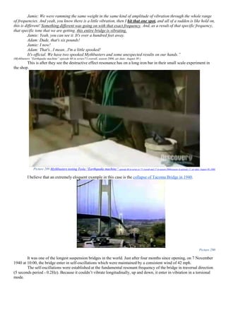
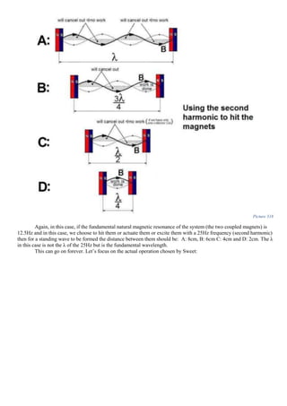
![Picture 287 Mythbusters testing Tesla “Earthquake machine” episode 60 in series or 71 overall and 17 in season 2006(season 4) episode 17, air date: August 30, 2006
A partial transcript of the experiment:
"All of a sudden, this myth is giving Adam and Jamie, a good vibe, and it's not the traffic because that's on a
completely separate bridge.
Picture 288 Mythbusters testing Tesla “Earthquake machine” episode 60 in series or 71 overall and 17 in season 2006(season 4) episode 17, air date: August 30, 2006
Adam: It totally feels like the whole structure is ringing to that Hertz. [...]
But the best is yet to come. After some more tuning, they find a sweet spot (sub-harmonic A/N)
Jamie: Oh my God. It feels like a big semi-trailer truck is rolling right by us right now!
Adam: And that's only 6 pounds of weight moving 25 times per second!
Jamie: It actually makes me a little concerned, believe it or not.
Adam: I'm totally stunned come out here and find this thing vibrating at the correct frequency to be felt
hundreds of feet away from the source. That is totally amazing. Did not expected that!](https://image.slidesharecdn.com/researchinsolidstatefreeenergygeneratorsver7-5-22-130606180846-phpapp02/85/Research-in-solid-state-free-energy-generators-ver-7-5-22-137-320.jpg)
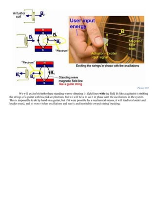
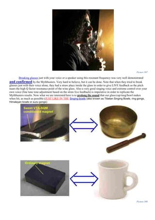
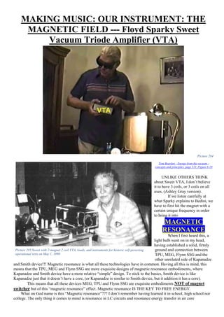
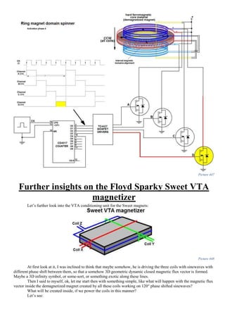
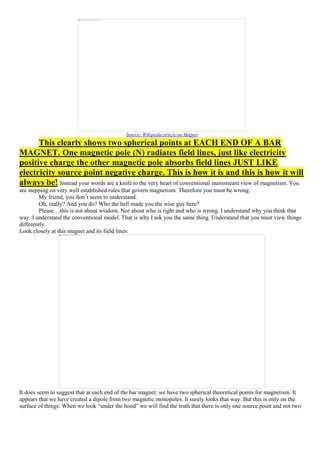
![Antique Old Tibetan singing bowl is exactly like a Sweet VTA
conditioned magnet
(An ordinary magnet is like an ordinary cup/mug/glass/bowl
but a Sweet VTA magnet is exactly like a Tibetan singing bowl)
This is the difference between a VTA magnet and an ordinary magnet.
The antique old Tibetan singing bowl is the most apparent/simple/unsophisticated/ordinary/common man-made
OVERUNITY device. More energy coming out than put in. More energy coming out in the form of self-oscillations
than the energy that it took to hit it. It doesn't even have to be hit, just slightly touched and it will sing, if it’s properly
constructed (made by hand).
This is what I mean when I say “self-oscillations”. Why make the sound last longer? Because we are
interested in hitting/touching the glass/cup/mug/bowl as rare as possible and not to use/expend to much energy in the
“hitting/touching” process compared to the energy that we will extract from the self-oscillations in this
glass/cup/mug/bowl.
Why do I say Overunity? You can say that if you were able to “stress” these sound waves, and extract all their
energy from them, then they will be instantly silenced. This is correct, but for this bowl to do work, it will have to be
constantly slightly and gently hit/struck/touched in-phase with the self-oscillating resonant frequency so that a
constructive interference pattern is created so that the natural self-oscillations will not fade away under a load.
Not every glass/cup/mug/bowl sings in self-oscillations at its
resonant frequency, therefore not every magnet will be a “singing”
magnet capable of maintaining its oscillations once struck or hit. This is
also backed up by Tom Bearden words in his book, I quote:
But fortunately unlike the glasses/cups/mugs or bowls, the magnet can be “conditioned” or “remolded” or
“remade” or “re-beaked” or to be more precise “re-magnetized” so that it will hold the “singing” self-oscillation longer
once struck. This is the “conditioning” phase we are after. I believe it to be a special re-magnetizing process using
the resonant frequency of the magnet/field using a very strange extremely unusual and unique re-magnetization process
using sinewave feed to the coil. A re-magnetization in both direction, not just one, so that a “shear” is created.
Therefore, our magnet will have a more dynamic field, rather than a static one, in theory anyway. This theory is an
educated guess, and partially backed up by Tom Bearden, I quote:
It’s not a dynamic field, forever or perpetually, it just the self-oscillation of the magnetic field. It will
eventually fade away, but the process can be restarted with yet another hit/struck/touched/spike/input signal. Because
this field doesn't make the subject to any type of friction, these self-oscillations in the magnetic field will in theory last a
lot longer than the sound waves oscillations in the Tibetan bowl which are subject to friction by moving the air back and
forth.
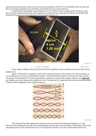
To determine the resonant frequency of a magnet/magnetic field we use a thin razor blade placed in unstable
equilibrium on top of a magnet (Picture 309 and Picture 310):
[...] the magnet was useless because it would not "hold" the activation and retain it. Magnets whose magnetic field
variation did not exceed 10% were ideal. So Sweet only found about 1 in 10 or even 1 in 30 magnets that would
retain the self-oscillation state when initiated.”
(“Energy from the vacuum - concepts and principles” page 309, paragraph 1)
“That fact can be used, e.g., to create magnets whose fields appear normal, but which deviate from the normal
behavior of ordinary magnets, and which produce anomalies in their magnetic fields.”
(“Energy from the vacuum - concepts and principles” page 363, paragraph 1)](https://image.slidesharecdn.com/researchinsolidstatefreeenergygeneratorsver7-5-22-130606180846-phpapp02/85/Research-in-solid-state-free-energy-generators-ver-7-5-22-148-320.jpg)
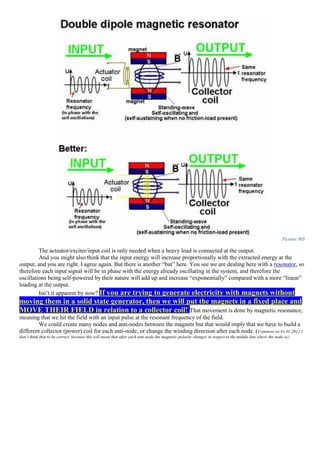
![Picture 309
Picture 310
These oscillations are reported by Tom Bearden to have happened by themselves (self-oscillating):
This is exactly like the sound keeps going in a Tibetan singing bowl!
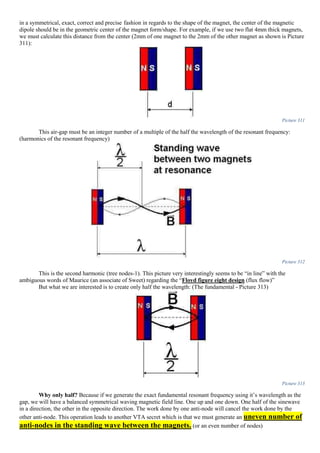
The air-gap or the distance between the magnets.
This air-gap must be extremely and precisely well calculated in order for the standing wave to be formed. This
is done using the formula:
𝑑[𝑚] =
1
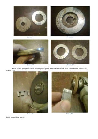
2 ∗ 𝑓𝑟𝑒𝑠𝑜𝑛𝑎𝑛𝑐𝑒[𝐻𝑧]
Equation 112
Where:
d-distance between the magnets expressed in meters;
fresonance -is the resonant frequency of the magnet/magnetic field expressed in Hertz.
Another very important point is that this distance is not the actual distance between the magnets but is the
distance between the centers of the two magnetic dipoles. Considering that the material of the magnet was magnetized
“I also locked up one of his specially conditioned magnets for 24 hours, with a piece of shim stock sitting on the flat
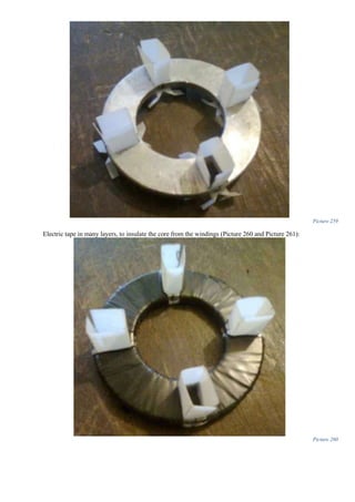
of the magnet and waving to and fro continuously, steadily performing work by moving air. When I opened the lock
the next day, the shim stock was still there on the magnet and oscillating, having continuously done work against the
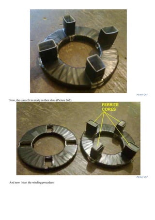
air resistance for 24 hours with absolutely no energy input by the operator. “
(Tom Bearden - Energy from the vacuum - concepts and principles page 307, paragraph 1)](https://image.slidesharecdn.com/researchinsolidstatefreeenergygeneratorsver7-5-22-130606180846-phpapp02/85/Research-in-solid-state-free-energy-generators-ver-7-5-22-149-320.jpg)
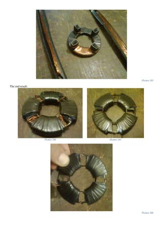
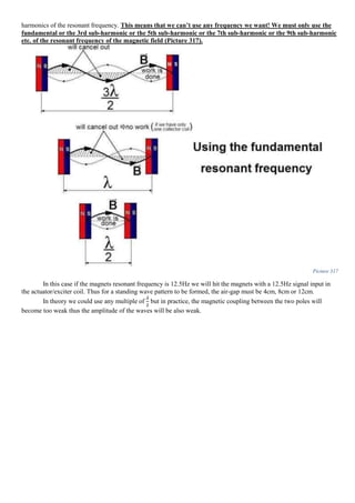
![If we carefully listen to what very few things Sparky is pointing out, few things but of an extreme importance,
we find out that after determining the resonant frequency of a magnet, that first each magnet has a slightly different
resonant frequency, and second, when we bring to identical magnets closer to each other, their fields gets mingled, and
the natural resonance frequency will be an average of the two:
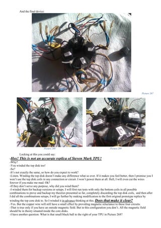
Picture 314
A partial transcript of Tom Bearden video of Sparky saying just this:
If we carefully analyze the videotape, and listen to what they are saying, we will understand that Sweet actually
tried to explain to Tom Bearden and John Bedini the working principle prior to the recording of the video. This is an
obvious rational deduction, based on the pre-indoctrinated/pre-fabricated answers (wrong answers) given especially by
Bedini to Sweet when he is trying to finish his sentences. This only leads to the conclusion that fortunately for us, they
most likely had a prior conversations about the working principle of operation behind the VTA and the
conditioner/conditioning of the magnets, prior to the videotaping. It is fortunately for us, because these “finishing the
sentences” wrong answers, gives us clues and deeper insights on how the VTA really works. Thanks to Bedini wrong
answer “Hole is?” we can say with extreme conviction that the air-gap is indeed extremely important, and as presented
above, without the proper determination of it, the standing wave will not form. Another point we must not ignore, is the
answer “With the iron bar, yeah” also made by Bedini. I’m not fully convinced, but I think he is referring either in
replicating the VTA effect in a transformer, where determining the iron-bar-core magnetic resonant frequency is crucial
for the operation (comment on 04.02.2012 this could also be more likely), or most likely his is referring to another not so obvious
conditioning secret, in using a coil with an iron-bar core for the re-conditioning (re-magnetizing) to increase the flux
density and facilitate an easier re-magnetization. Thus the resonant magnetic frequency will change because we have
added an additional mass that captures and distorts the magnetic field, changing the resonant frequency of the system.
Thus an additional determination of the magnetic resonance of the iron bar will be required.
The fact that Sparky Sweet is swearing and not only that he is swearing twice, denotes to me that most likely he
was somehow “traumatized” and extremely annoyed and frustrated by not finding the right maximum amplitudes at the
“[...] Sweet: You have to take two magnets now. Right? Find out first what that...
Bedini: Hole is? (Most likely referring to the air-gap A/N)
Sweet: No, no. Find out first what the frequency is. The natural frequency. The magnetic resonant frequency.
Bedini: With the Iron bar, yeah.
Sweet: Find out what that is. Right? Then, I just took the two magnets, found what the maxim is, and I put them
together like this. [...]
Sweet: Then I found what the frequency was. Now what it will do, what will do, it will average out the God damn
frequency, God damn resonant frequency in this one and that one.
Bedini: Right.
Sweet: It will average it out. Right? […]”
(Floyd Sparky Sweet VTA-SQM Secrets videoclip filmed by Tom Bearden in Sherman Oaks, California April/May 1987 minute 6 second 30 part 4 –permalink click here)](https://image.slidesharecdn.com/researchinsolidstatefreeenergygeneratorsver7-5-22-130606180846-phpapp02/85/Research-in-solid-state-free-energy-generators-ver-7-5-22-151-320.jpg)


![There is no other logical psychological reason behind his swearing besides the frustration he had when he
experienced this beat frequency.
Think about it. If you have a beat frequency of 2 minutes, then it means that your period T will be 120 seconds.
This means a beat frequency of 0,008 Hz or 8.3 mHz. This means that the first magnet had the natural resonant
frequency at 12,512 Hz let’s say and the other magnet had the natural magnetic resonant frequency at 12,520 Hz. For
this reason a beat frequency of 2 minutes had to happen, due to the desynchronization of the two established wobbling
domains spin in the VTA magnets.
So the answer and the solution to our problem is to create a wobbling domain spin in each magnet through a
dynamic re-magnetization process for our demagnetized magnets, at precisely 12,516 Hz (average of the two for our
given example). And this is why Sweet insists on FIRST accurately determining the natural magnetic resonant
frequency of each particular magnet first thing first.
The reason for this, again, as I stated, is that you will have to know this frequency prior of the demagnetization
process of the magnets (prior of “screwing up” the magnetism by heating them above Curie point). And only after that
determination, you know now at what frequency you should set up the wobbling domain spin wave so that it will
be self-sustaining.
The Floyd Sweet VTA-SQM Time-machine/antigravity device
Any researcher in this fringe domain (that is kind-of separated from the free-energy domain of study)
will tell you that antigravity devices are also time-machines. The reason behind this is that gravity and time are
intimately connected in the space-time fabric of the universe. Gravity directly affects time. This is a fundamental fact.
No one can argue with that. Amazingly enough Tom Bearden in his book “Energy from the vacuum - concepts and
principles” describes the Floyd VTA as an antigravity device also:
Picture 465
Tom Bearden - Energy from the vacuum - concepts and principles, page 319, Figure 6-14
What we see in Picture 465 is a simple weight of the VTA to load of the VTA graph.
[...] it will average out the God damn frequency, God damn resonant frequency in this one and that one […]”
(Floyd Sparky Sweet VTA-SQM Secrets videoclip filmed by Tom Bearden in Sherman Oaks, California April/May 1987 minute 7 second 36 part 4 –permalink click here)
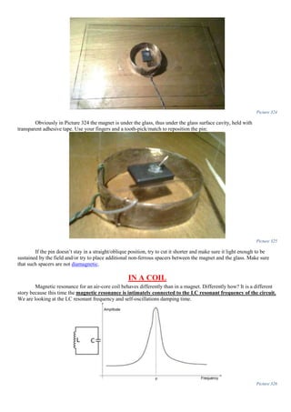
“[…] we noticed that, at full power output of 500 watts, his unit weighed a little less on the bench than when not
powered.”
(Tom Bearden - Energy from the vacuum - concepts and principles” page 316 paragraph 3)](https://image.slidesharecdn.com/researchinsolidstatefreeenergygeneratorsver7-5-22-130606180846-phpapp02/85/Research-in-solid-state-free-energy-generators-ver-7-5-22-245-320.jpg)
![Picture 475
When I look at this (Picture 475), it makes me cry, and shout towards the sky. This is so sad! It makes me bitter
just by looking at how he powers it. Naudin definitely was in a hurry to test it out, so he ignored all the firing sequence,
control circuit, family groups, and all that. It’s insane! Marko clearly said that we shouldn’t try this: (click here to hear
Marko saying this)!
Quote:
This clearly means we shouldn't try to power both wires/coils at the same time.
Maybe I’m wrong, but if I do, then let’s analyze Marko words in more detail.
Right here in his own words he describes the signal that we have to use to power the coil. Let’s quote him when
he describes this signal:
So in my mind this is what he’s describing:
We will call this the <Standard firing sequence for the standard
configuration Marko Rodin coil>
“[…] they are so separated from one another, than that’s why one wire is on at a given time, because if both wires
have the same family number group on at the same time, then this coil wouldn’t work, it will have resistance”.
(Marko Rodin's vortex-based mathematics part 19 of 44 minute 0 second 49 permalink)
“That one wire…there’s two wires here. That one wire, ALL the positives are in one wire at a minute of the
first stage. There’s three stages. It’s a firing stage. The first activation sequence of this coil, only the right wire is
all positive (that’s your 1, 4, 7). The second activation stage is all your left wire is all positive (is activated). And
now the first family number group 1, 4, 7…the other wire is totally off. And then they’re both off. None of them are
positive, they’re all neither positive, and the middle space in there becomes all positives (The 3, 9, 6)”
(Marko Rodin's vortex-based mathematics part 18 of 44 minute 4 second 13 permalink)](https://image.slidesharecdn.com/researchinsolidstatefreeenergygeneratorsver7-5-22-130606180846-phpapp02/85/Research-in-solid-state-free-energy-generators-ver-7-5-22-253-320.jpg)
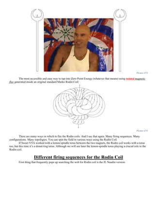
![Picture 476
But wait, later, in the http://www.youtube.com/watch?v=-9MKHMfy4T0& - t=1m50spresentation, Marko describes a
different type of activation sequence.
Let me quote this particular conversation in case you didn’t follow the link, and to make sure I understand it right:
In my mind by the word “wire” I understand “coil” right? So Marko answer to Charlie question will look like this:
"[...] when it hits one coil the electricity goes in one way, when it hits the other coil it goes in the opposite
direction."
Now from his words can be deduced that the new activation sequence will look like this: (Firing sequence version 2)
Picture 477
But wait again! It’s getting trickily by the minute! Let’s turn back a few seconds in the same conversation, and analyze
Marko words again. To me, this guy Charlie definitely knows how to put the right questions, but is the answers of
Marko that are confusing):
“[Charlie:] 1, 4 and 7 are ALWAYS POSITIVE? (Just like in my presented signal diagram above - Picture
477)
[Marko:] No. (Ups! It means that my firing sequence is not right)
“[Charlie:]-So, you are saying the polarity switches when the current reverses its direction?
[Marko:]- [...] when it hits one wire the electricity goes in one way, when it hits the other wire it goes in the
opposite direction.”
(Marko Rodin's vortex-based mathematics part 19 of 44 minute 1 second 50 permalink)](https://image.slidesharecdn.com/researchinsolidstatefreeenergygeneratorsver7-5-22-130606180846-phpapp02/85/Research-in-solid-state-free-energy-generators-ver-7-5-22-254-320.jpg)
![[Marko:] 1, 4, 7 are always positive… (Marko is interrupted here)
[Charlie:] Then they flip? They reverse the polarity? Is that what you mean?
[Marko:]OR1, 4, 7 are always negative.”
(Marko Rodin's vortex-based mathematics part 19 of 44 minute 0 second 10 permalink)
Ok, in that 2 letter word there “OR” may lay the key. In that 2 letter word “OR” may lay the
information that the presented signal diagrams for the activation sequence of the Rodin coil may be correct. In that 2
letter word “OR” could lay the information that the Rodin coil could run like this:
Picture 478
Same signal (firing sequence) but the wires are reversed. Same thing. No difference in operation. Only a
conceptual difference. Same meat different gravy.
But wait again! Dear God! It’s getting more confusing by the second! Let’s continue the conversation:
“[Marko:] This coil here…the negative 1, 4, 7 are ALL on the wire that the positive 8, 2, 5 are on. You don’t
have…And the positive 8, 2, 5… and the positive 1, 4, 7 all have the negative 8, 2, 5” (Marko Rodin's vortex-based mathematics part 19 of
44 minute 0 second 30 permalink)
This one’s the nasty one. Can’t figure out the head and tail of this one. It could describe this type of signal: (Firing
sequence version 3)
Picture 479](https://image.slidesharecdn.com/researchinsolidstatefreeenergygeneratorsver7-5-22-130606180846-phpapp02/85/Research-in-solid-state-free-energy-generators-ver-7-5-22-255-320.jpg)

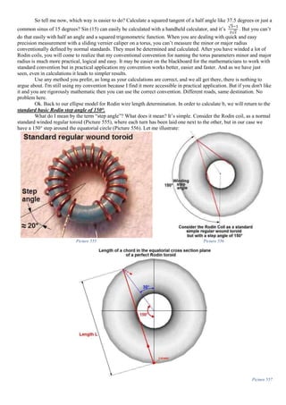
![Picture 550
So, now let’s take this step by step. What do we need? We need the perimeter of an ellipse. It is also called
circumference of the ellipse. This is not an easy equation, but we can use simpler approximate versions instead.
We can use Ramanujan equation for the circumference of the ellipse:
𝐶 ≈ 𝜋 [3(𝑎 + 𝑏) − √(3𝑎 + 𝑏)(𝑎 + 3𝑏)] Equation 151
Or a better approximation given by the
Equation to approximate the small Rodin turn (complete turn/12) using the ellipse model:
𝐶 ≈ 𝜋(𝑎 + 𝑏)
[
1 +
3 (
𝑎 − 𝑏
𝑎 + 𝑏
)
2
10 + √4 − 3 (
𝑎 − 𝑏
𝑎 + 𝑏
)
2
]
Equation 152
Where a and b are given by:
Picture 551
Or they could be reversed; it is not relevant in our case.
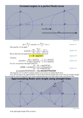
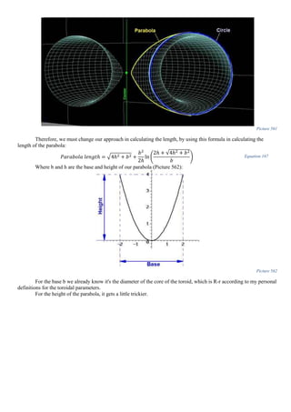
Variable “a” is simple. It is the radius of the core of the perfect Rodin torus:](https://image.slidesharecdn.com/researchinsolidstatefreeenergygeneratorsver7-5-22-130606180846-phpapp02/85/Research-in-solid-state-free-energy-generators-ver-7-5-22-293-320.jpg)
![R (Major radius) R+r
r (Minor radius) R-r
(R+r)/2 R (Major radius)
(R-r)/2 r (Minor radius)
Table 2
Note: One should learn these conversions by heart if wants to really follow my calculations. I will often switch back and forth between these two conventions, because
sometimes it’s easier one way and harder the other and vice-versa.
RODIN PERFECT TORUS CONDITION USING STANDARD
CONVENTION NAMING PARAMETERS FOR A TORUS
Ok. In simpler terms the standard convention major radius is in my definition the semi-sum and the standard
minor radius as the semi-difference.
Generally in my calculations I will make these notations:
r-minor radius in my convention for torus parameters;
R-major radius in my convention for torus parameters;
rc-minor radius standard convention for torus parameters;
Rc –major radius standard convention for torus parameters;
Now, I will start from previous determined condition, and we write:
R ∗ sin(15°) = 𝑟 Equation 139
But from my convention we know that:
𝑅 𝑐 =
𝑅 + 𝑟
2
Equation 154
𝑟𝑐 =
𝑅 − 𝑟
2
Equation 155
Ok. Now let’s substitute Equation 139Error! Reference source not found. in Equation 154 and write it like
this:
Equation 139 ⟶ Equation 154 ⟹
𝑅 𝑐 =
𝑅 + 𝑅 ∗ sin(15°)
2
=
𝑅[1 + sin(15°)]
2
⟺ 𝑅 =
2𝑅 𝑐
1 + sin(15°)
Equation 156
Let’s modify Equation 139 like this:
Equation 139Error! Reference source not found. ⟺ 𝑅 =
𝑟
sin(15°)
Equation 157
Substitute this in Equation 155 and we get:
Equation 157 → Equation 155 ⇒ 𝑟𝑐 =
𝑟
sin(15°)
− 𝑟
2
Equation 158
Bring above at the same denominator:
Equation 158 ⟺ 𝑟𝑐 =
𝑟
sin(15°)
−
𝑟 ∗ sin(15°)
sin(15°)
2
=
𝑟 − 𝑟 ∗ sin(15°)
sin(15°)
2
=
𝑟[1 − sin(15°)]
2 ∗ sin(15°)
⟹ 𝑟 =
2 ∗ 𝑟𝑐 ∗ sin(15°)
1 − sin(15°)
Equation 159
Ok. Now. I’m going to rewrite our original condition in Equation 139 using these standard conventional
parameters. So we substitute Equation 156 and Equation 159 in Equation 139Error! Reference source not found. and
we write:
Equation 156, Equation 159
𝑖𝑛
→ Equation 139Error! Reference source not found. ⇒
2𝑅 𝑐
1 + sin(15°)
∗ sin(15°) =
2 ∗ 𝑟𝑐 ∗ sin(15°)
1 − sin(15°)
|: [2 ∗ sin(15°)] ⟺
𝑅 𝑐
1 + sin(15°)
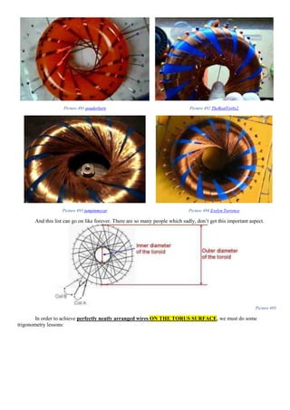
=
𝑟𝑐
1 − sin(15°)
Equation 160
Equation 160 ⟹ 𝑟𝑐 = 𝑅 𝑐 ∗ [
1 − sin(15°)
1 + sin(15°)
] = 𝑅 𝑐 ∗
𝑐𝑜𝑣𝑒𝑟𝑠𝑖𝑛(15°)
𝑐𝑜𝑣𝑒𝑟𝑐𝑜𝑠𝑖𝑛(15°)
= 𝑅 𝑐 ∗
𝑣𝑒𝑟𝑠𝑖𝑛(75°)
𝑣𝑒𝑟𝑐𝑜𝑠(75°)
= 𝑅 𝑐 ∗
2 ∗ sin2(37,5°)
2 ∗ cos2(37,5°)
Equation 161
Where the coversine, covercosine, versin and vercos are the historic shorthands used in the past for navigation and to calculate the distance between two points on a
sphere.
And we finally write:
𝒓 𝒄 = 𝑹 𝒄 ∗ 𝐭𝐚𝐧 𝟐( 𝟑𝟕, 𝟓°) Equation 162
Where:
rc-minor radius standard convention for torus parameters;
Rc –major radius standard convention for torus parameters;](https://image.slidesharecdn.com/researchinsolidstatefreeenergygeneratorsver7-5-22-130606180846-phpapp02/85/Research-in-solid-state-free-energy-generators-ver-7-5-22-295-320.jpg)
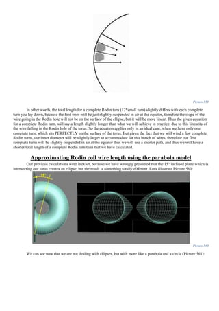
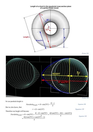
![This length L of a small Rodin turn (from one pole to another) can be easily determined from Equation 163:
𝐿 = 2 ∗ 𝑅 ∗ sin(
𝛼
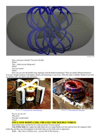
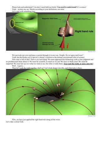
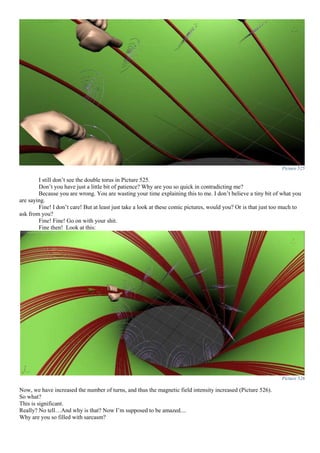
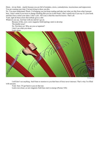
2
) = 4 ∗ 𝑏 Equation 163
Where in our case α is 150 degrees
This length can be easily seen that it is four times our b in the ellipse:
𝑏 =
𝐷 ∗ 𝑠𝑖𝑛(75°)
4
=
𝑅 ∗ sin(75°)
2
Equation 164
From all of this, we can now write the
Equation to approximate the total length of a complete Rodin turn using
ellipse model:
𝐿 𝑡𝑜𝑡𝑎𝑙 ≅ 12 ∗ 𝜋 ∗ (
𝐷 − 𝑑
4
+
𝐷 ∗ sin(75°)
4
) ∗
[
1 +
3 (
1 −
𝑑
𝐷
− sin(75°)
1 −
𝑑
𝐷
+ sin(75°)
)
2
10 + √4 − 3 ((
1 −
𝑑
𝐷
− sin(75°)
1 −
𝑑
𝐷
+ sin(75°)
)
2
)
]
Equation 165
Picture 558
To simplify Equation 165 we will reach this constant:
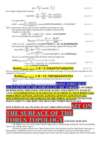
𝑹𝒐𝒅𝒊𝒏 𝑭𝒖𝒍𝒍−𝒕𝒖𝒓𝒏 ≅ 𝑹 ∗ 𝟑𝟐. 𝟑𝟏𝟕𝟕𝟖𝟕𝟔𝟓𝟔𝟏𝟔𝟔𝟓𝟎 Equation 166
Although this might seem neat, fancy, extravagant, cool, or whatever, it is not correct. You could try to verify
the above formula by taking a perfect Rodin torus, and again I repeat myself, a perfect Rodin torus is a toroid where the
inner hole diameter is smaller than the total big diameter of the whole torus with a factor of sin (15°). So take such a
torus, measure the diameters, and calculate a complete Rodin turn using the above formula. Then take a piece of sewing
string, cut it at the result you get, and verify the equation.
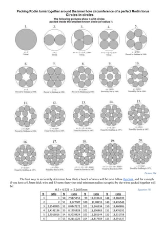
Note that first thing first, this formula is an approximation, and is very close to reality so you don’t have to
worry, unless you are planning for more than 100 complete turns in Rodin coil A for example, which is a titanic work.
Second, this formula only applies to only one complete turn! When you have winded 2 complete turn, the 3rd
winding will theoretically arrange itself with the two before it in a compact close together cylinders (packaging). It
depends on how many complete turns you have (Picture 559):](https://image.slidesharecdn.com/researchinsolidstatefreeenergygeneratorsver7-5-22-130606180846-phpapp02/85/Research-in-solid-state-free-energy-generators-ver-7-5-22-297-320.jpg)
![Equation 169 =
𝑅[2 sin(60° + 15°) + sin(15°) − 1]
2
=
𝑅[2 sin(60°) cos(15°) + 2 cos(60°) sin(15°) + sin(15°) − 1]
2
=
𝑅 [√3 ∗ (
1 + √3
2√2
) +
2(√3 − 1)
2√2
− 1]
2
=
𝑅 (
√3 + 3 + 2√3 − 2 − 2√2
2√2
)
2
= 𝑅 (
3√3 − 2√2 + 1
4√2
) = 𝑅 ∗ 0,595335348
Equation 170
So now, I'm not going to go in too much detail, due to extreme complexity of the equation, but what I'm going
to give is the end result:
𝑺𝒎𝒂𝒍𝒍 𝑹𝒐𝒅𝒊𝒏 𝒕𝒖𝒓𝒏 = 𝑹 ∗ 𝟓, 𝟓𝟒𝟑𝟏𝟎𝟗𝟔𝟗𝟖𝟖 Equation 171
𝑹𝒐𝒅𝒊𝒏 𝑭𝒖𝒍𝒍−𝒕𝒖𝒓𝒏 ≅ 𝑹 ∗ 𝟑𝟑, 𝟐𝟓𝟖𝟔𝟓𝟖𝟏𝟗𝟐𝟖 Equation 172
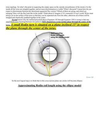
1. The correct determination of the Rodin coil length using the lemniscate
model
What we are really dealing here is something along the lines of Cassinian ovals. We must study the Curves of
Perseus produced by intersecting (cutting) a ring torus (donut torus) with a plane. NOT an inclined plane like in
Villarceau circles, but a plane that is parallel to the axis of the torus and tangent to the interior inner circle of the torus
(the circle formed by the inner radius), this gives a plane curve, called a "spiric section of Perseus". Thus we are dealing
with a special case of curves of Perseus called the curve of Booth or the hippopede of Proclus.
Picture 565 Picture 566
So we are dealing with a special hippopede ("foot of a horse" or "horse fetter") called the "hippopede of
Proclus", aka "lemniscate of Booth" which is a special curve of Booth that is hyperbolic and NOT elliptic or oval.
So in other words, we are trying to determine the total arc length of the hyperbolic Booth lemniscate, or simply put
what is the length of the infinity symbol? How long is the infinity? If you catch my drift.
The lemniscate of Bernoulli is both a curve of Booth and a curve of Cassini.
These curves were studied by Jakob Bernoulli, Cassini, Gauss, and Euler. Their study has led to interesting
problems in approximation theory and elliptic functions.
Lemniscate of Bernoulli](https://image.slidesharecdn.com/researchinsolidstatefreeenergygeneratorsver7-5-22-130606180846-phpapp02/85/Research-in-solid-state-free-energy-generators-ver-7-5-22-301-320.jpg)
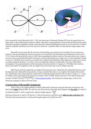

![Picture 574
In the Rodin lemniscate, we can calculate further this ratio.
Picture 575
We do know that in the Bernoulli lemniscate, the ratio between the total lemniscate length and its height, is:
2𝑎√2
𝑎
= 2√2 = 2.828427124746190 Equation 175
In other words, the length of Bernoulli lemniscate is 2√2 longer than its height (Picture 575).
Now let's look at the Rodin lemniscate:
Picture 576
We don't want to work with two variables R and r so knowing their relationship:
𝑟 = 𝑅 ∗ sin(15°) Equation 139
we can easily know that the Rodin lemniscate height is:
𝐻𝑒𝑖𝑔ℎ𝑡 = 𝑅 − 𝑟 = 𝑅 − Equation 139 = 𝑅 − 𝑅 ∗ sin(15°) = 𝑅[1 − sin(15°)] Equation 176
Now let's make their ratio:
𝐿𝑒𝑛𝑔𝑡ℎ
𝐻𝑒𝑖𝑔ℎ𝑡
=
Equation 163
Equation 176
=
2𝑅 sin(75°)
𝑅[1 − sin(15°)]
=
2 sin(75°)
[1 − sin(15°)]
Equation 177
But we want to work with the same angle in order to identify trigonometric identities, so let's transform the denominator
in Equation 177 in its equivalent form:](https://image.slidesharecdn.com/researchinsolidstatefreeenergygeneratorsver7-5-22-130606180846-phpapp02/85/Research-in-solid-state-free-energy-generators-ver-7-5-22-305-320.jpg)
![2 sin(75°)
[1 − sin(15°)]
=
2 sin(75°)
[1 − cos(75°)]
=
2 sin(75°)
𝑣𝑒𝑟𝑠𝑖𝑛(75°)
Equation 178
Where the versin in Equation 178 is the less known versed sine (flipped sine) which equals:
2 sin(75°)
𝑣𝑒𝑟𝑠𝑖𝑛(75°)
=
2 sin(75°)
2𝑠𝑖𝑛2(
75°
2
)
=
sin(75°)
𝑠𝑖𝑛2(37.5°) Equation 179
But again, we want to work with the same angle, so let's write our ratio like this:
sin(75°)
𝑠𝑖𝑛2(37.5°)
=
sin(2 ∗ 37.5°)
𝑠𝑖𝑛2(37.5°)
Equation 180
Now we recognize in Equation 180 a trigonometric identity at the nominator:
sin(2 ∗ 37.5°)
𝑠𝑖𝑛2(37.5°)
=
2 sin(37.5°) cos(37.5°)
𝑠𝑖𝑛2(37.5°)
Equation 181
The power two of the sinus at the denominator gets reduced with one of the sinus at the nominator in Equation 181 so
our ratio will be:
2 sin(37.5°) cos(37.5°)
𝑠𝑖𝑛2(37.5°)
=
2 cos(37.5°)
sin(37.5°)
Equation 182
But this is cotangent of 37.5°. So, we have finally determined the:
Exact ratio for perfect Rodin lemniscate parameters:
2 cos(37.5°)
sin(37.5°)
=
𝟐 𝐜𝐨𝐭(𝟑𝟕. 𝟓°) =
𝑻𝒐𝒕𝒂𝒍 𝑳𝒆𝒏𝒈𝒕𝒉 𝒐𝒇 𝑹𝒐𝒅𝒊𝒏 ∞
𝑻𝒐𝒕𝒂𝒍 𝑯𝒆𝒊𝒈𝒉𝒕 𝒐𝒇 𝑹𝒐𝒅𝒊𝒏 ∞
= 𝟐. 𝟔𝟎𝟔𝟒𝟓𝟎𝟕𝟒𝟓𝟔𝟖𝟐𝟒𝟏𝟎
≠ 2.828427124746190 (𝑓𝑟𝑜𝑚 𝑡ℎ𝑒 𝐵𝑒𝑟𝑛𝑜𝑢𝑙𝑙𝑖 𝑙𝑒𝑚𝑛𝑖𝑠𝑐𝑎𝑡𝑒 𝑝𝑎𝑟𝑎𝑚𝑒𝑡𝑒𝑟𝑠 𝑟𝑎𝑡𝑖𝑜 Equation 175)
Equation 183
Constructing the Rodin lemniscate
What we are trying to accomplish is to build the Rodin lemniscate starting from the end result. I mean normally
to construct a lemniscate we must know the distance between the foci, but this is exactly what we don't know in our
case. What we have to do is trace back the solution. We must start from the end result. We know the end result and after
we are done we finally determine the startup variables using advanced Euclidian trigonometry.
We know the length of the lemniscate, we know its height, but we don't know its foci. How do we construct it?
Solution:
For a total distance D of the entire Rodin lemniscate length, we determine the radius of the circle with its origin on one
of the foci is D/2.
One of the foci is departed from the extremities of the lemniscate by approximate
2.8702296521445457615670381627828.
Divide D/2 at this constant and you will get a value which is the length of the segment from the outmost eccentric
lemniscate point and its focal point.
To find out the foci distance in the Rodin lemniscate divide the length of the lemniscate by:
3,298243911904550
To find the approximate area of a Rodin Lemniscate multiply the square radius of the whole torus by
1.0298578492491697286021559856865
<working on proof>
<work temporary abandoned>
One Rodin full turn wire length calculation
(multiply the radius of the torus with this value)
Using straight lines
Using the ellipse
model
Using the parabola
model Using Bernoulli lemniscate model Using the Rodin lemniscate model](https://image.slidesharecdn.com/researchinsolidstatefreeenergygeneratorsver7-5-22-130606180846-phpapp02/85/Research-in-solid-state-free-energy-generators-ver-7-5-22-306-320.jpg)

![Picture 586 Picture 587
Picture 588
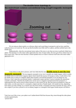
Naudin, back in 1999, built the Moebius Tripole (Picture 587) which creates a tripole field (Picture 588) closely
resembling the double torus (Picture 586).
You are wrong!
Why?
You are mistaken, when you say, and I quote: “[…] tripole field closely resembling the double torus”.
Why?
Because, it doesn’t resemble at all!
What?
IT’S EXACTLY THE DOUBLE TORUS! Allow me to also illustrate the irrelevant knots done along the iron
bar (core) in the working of the device and the field that creates (Picture 589):
Picture 589
Notice it’s the same original old Naudin design (Picture 587). There is not a single difference from his
schematic, so I haven’t changed anything…YET.
Let’s look at these knots, shall we?
Why?
Because, it’s important.
Why?
I want to prove something.](https://image.slidesharecdn.com/researchinsolidstatefreeenergygeneratorsver7-5-22-130606180846-phpapp02/85/Research-in-solid-state-free-energy-generators-ver-7-5-22-314-320.jpg)


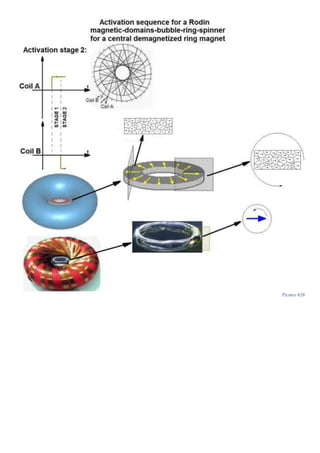
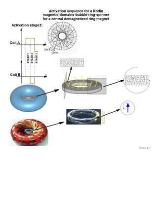
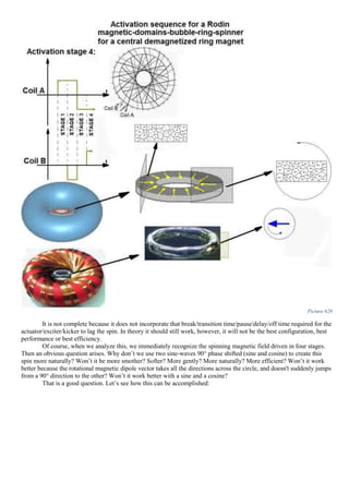
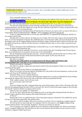
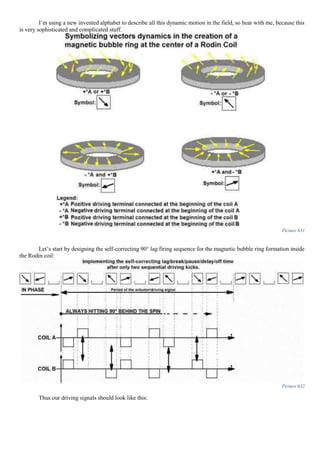
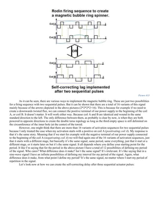
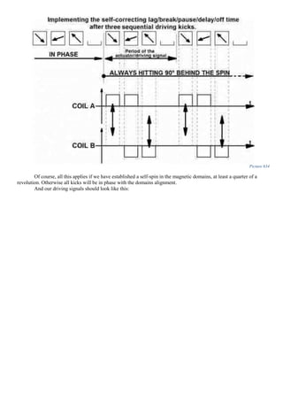
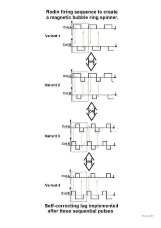
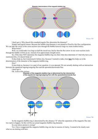
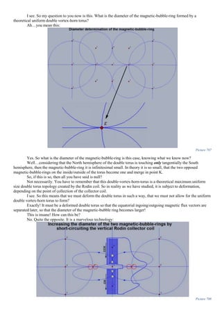
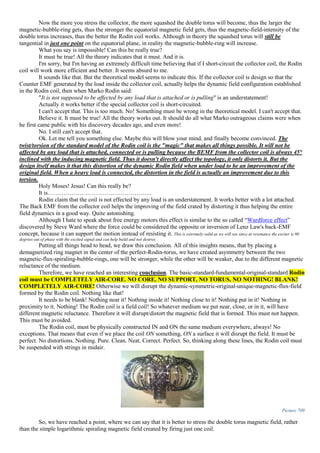
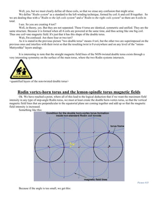
![Picture 629
Interesting configuration. However, I will give you three good unbreakable reasons why this should NOT work:
1. As we will see, there is no way to implement (at least in the drawing presented) the essential 90° lag between
the actuator field and the spinning magnetic bubble ring. This will make sense later on.
2. Marko clearly stated that his coil works in PDC (Pulsed Direct Current). My guess is probably because of the
reason 1.
3. Studying the physics of the bubble rings
Picture 630 Diver blowing bubble rings (photos: Wim Bakker)
and how some scuba divers are able to imitate the dolphins and to create such water bubble rings, we find out
that abrupt closing and opening and sudden release of pressure is crucial and essential for success in the technique
described here.
Quote:
Who am I? What do I seek? What I am doing here? And why?
For the Rodin coil to work correctly we must incorporate the necessary break/transition time/pause/delay/off
time in the firing sequence.
Why?
As I stated it is required.
“[...].Abrupt closing is essential. [...] Rings can be created by letting air escape through an orifice that is opened
and closed abruptly.”
Source: http://www.deepocean.net/deepocean/index.php?science09.php](https://image.slidesharecdn.com/researchinsolidstatefreeenergygeneratorsver7-5-22-130606180846-phpapp02/85/Research-in-solid-state-free-energy-generators-ver-7-5-22-344-320.jpg)


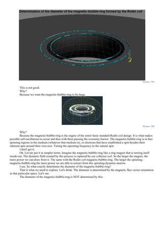
![111 120 69 1 37 60 0,5664062 0,0879369 1,648252 197,7902853 31,4793016 7,879904334
112 45 68 2,667 14 45 0,5591929 0,0854812 1,658075 74,61338153 11,87508849 8,045877735
114 60 66 2 19 30 0,544639 0,0806647 1,677341 100,6404682 16,01742798 8,385044358
115 72 65 1,667 23 36 0,5372996 0,0783043 1,686783 121,4483682 19,32910813 8,55829286
116 90 64 1,333 29 45 0,5299193 0,075976 1,696096 152,6486573 24,29478837 8,734022223
117 40 63 3 13 20 0,5224986 0,0736799 1,70528 68,21121315 10,85615175 8,912260905
118 180 62 0,667 59 90 0,5150381 0,0714163 1,714335 308,5802283 49,11206867 9,093037682
120 3 60 40 1 3 0,5 0,0669873 1,732051 5,196152423 0,826993343 9,462322208
122 180 58 0,667 61 90 0,4848096 0,0626901 1,749239 314,8630946 50,1120179 9,842112258
123 120 57 1 41 60 0,4771588 0,0605914 1,757634 210,916107 33,56834101 10,03602207
124 90 56 1,333 31 45 0,4694716 0,0585262 1,765895 158,9305667 25,2945853 10,23264909
125 72 55 1,667 25 36 0,4617486 0,0564946 1,774022 127,72956 20,32879085 10,43202421
126 20 54 6 7 10 0,4539905 0,0544967 1,782013 35,64026097 5,672323706 10,63417856
128 45 52 2,667 16 45 0,4383711 0,050603 1,797588 80,89146417 12,87427638 11,04695085
129 120 51 1 43 60 0,4305111 0,0487074 1,805171 216,6204682 34,4762183 11,25763235
130 36 50 3,333 13 18 0,4226183 0,0468461 1,812616 65,25416067 10,38552223 11,47122019
132 30 48 4 11 15 0,4067366 0,0432273 1,827091 54,81272746 8,723716519 11,90724448
134 180 46 0,667 67 90 0,3907311 0,0397476 1,84101 331,3817472 52,74104312 12,35528491
135 8 45 15 3 4 0,3826834 0,0380602 1,847759 14,78207252 2,352639911 12,58389359
136 45 44 2,667 17 45 0,3746066 0,0364081 1,854368 83,44654691 13,28093042 12,81560549
138 60 42 2 23 30 0,3583679 0,0332098 1,867161 112,0296512 17,83007276 13,28847253
140 18 40 6,667 7 9 0,3420201 0,0301537 1,879385 33,82893435 5,384042121 13,77415399
141 120 39 1 47 60 0,3338069 0,0286793 1,885283 226,2339579 36,00625269 14,02188418
142 180 38 0,667 71 90 0,3255682 0,0272407 1,891037 340,3866872 54,17422383 14,27291889
144 5 36 24 2 5 0,309017 0,0244717 1,902113 9,510565163 1,513653457 14,7850365
145 72 35 1,667 29 36 0,3007058 0,0231415 1,907434 137,3352409 21,85758245 15,04618657
146 180 34 0,667 73 90 0,2923717 0,0218476 1,91261 344,2697121 54,79222644 15,31077549
147 120 33 1 49 60 0,2840153 0,0205901 1,917639 230,1167364 36,62421608 15,57883659
148 90 32 1,333 37 45 0,2756374 0,0193692 1,922523 173,0271053 27,53811909 15,85040305
150 12 30 10 5 6 0,258819 0,0170371 1,931852 23,18221983 3,689564878 16,40418379
152 45 28 2,667 19 45 0,2419219 0,0148521 1,940591 87,32661536 13,8984625 16,97237867
153 40 27 3 17 20 0,2334454 0,013815 1,94474 77,78959363 12,38059835 17,26196165
154 180 26 0,667 77 90 0,2249511 0,012815 1,94874 350,7732233 55,8272924 17,5552437
155 72 25 1,667 31 36 0,2164396 0,011852 1,952592 140,586625 22,37505631 17,85225584
156 30 24 4 13 15 0,2079117 0,0109262 1,956295 58,68885604 9,340621544 18,15302859
158 180 22 0,667 79 90 0,190809 0,0091864 1,963254 353,385786 56,24309467 18,76597531
159 120 21 1 53 60 0,1822355 0,0083725 1,96651 235,9811778 37,55757093 19,07820745
160 9 20 13,33 4 9 0,1736482 0,0075961 1,969616 17,72653955 2,821266394 19,39431644
162 20 18 6 9 10 0,1564345 0,0061558 1,975377 39,50753362 6,287819266 20,03827345
164 90 16 1,333 41 45 0,1391731 0,004866 1,980536 178,2482524 28,36909046 20,69805489
165 24 15 5 11 12 0,1305262 0,0042776 1,98289 47,58935335 7,574080824 21,0339409
166 180 14 0,667 83 90 0,1218693 0,0037269 1,985092 357,3166146 56,86870546 21,37385433
168 15 12 8 7 15 0,1045285 0,0027391 1,989044 29,83565686 4,74849227 22,06584834
170 36 10 3,333 17 18 0,0871557 0,0019027 1,992389 71,72601826 11,41555035 22,77419418
171 40 9 3 19 20 0,0784591 0,0015413 1,993835 79,7533867 12,69314572 23,13454234
172 90 8 1,333 43 45 0,0697565 0,001218 1,995128 179,561529 28,57810494 23,49902751
174 60 6 2 29 30 0,052336 0,0006852 1,997259 119,8355442 19,07241921 24,24045987
175 72 5 1,667 35 36 0,0436194 0,0004759 1,998096 143,8629439 22,89649865 24,61742834
176 45 4 2,667 22 45 0,0348995 0,0003046 1,998782 89,94517443 14,31521912 24,99857619
177 120 3 1 59 60 0,0261769 0,0001713 1,999315 239,917758 38,18409712 25,38390944
178 180 2 0,667 89 90 0,0174524 7,615E-05 1,999695 359,9451703 57,28705309 25,77343209
180 2 0 60 1 1 0 0 2 4 0,636619772 26,56505118
Table 4
The Table 4 was done in Excel using these formulas:
First column are all the numbers from 1 to 180 without the primes (7, 11, 13, 17, 19… 169, 173, 179). We can’t have a
prime step-angle because one of its multiple must divide by 360, meaning that our wire must eventually end where it
started. Since prime numbers can only divide by 1 and themselves, they must be discarded from our table. We can't have
a step-angle larger than 180° because it's like for example you have a step-angle of 200° which is the same as saying
you have a step-angle of 160°=[180° − (200° − 180°)] in the other winding direction. So it's the same story just that
it's reversed.
The second column-"Number of outer points" was produced using the simple algorithm previously described. Again,
the number of points a specific winding creates is given by the first multiple of the step-angle that divides itself by 360.
(Least common multiple of the step angle and 360 all divided by the step angle)
𝐿𝐶𝑀(𝑠𝑡𝑒𝑝 𝑎𝑛𝑔𝑙𝑒, 360)
𝑠𝑡𝑒𝑝 𝑎𝑛𝑔𝑙𝑒
Equation 184
Angle at one of the outer points=(360-A2*2)/2
Angle per sector(band)= =(360/B2)/3
Nr of complete 360° revolutions, before ending where we started=(A2*B2)/360 or =LCM(A2;360)/360 (Least common
multiple of the step angle and 360 all divided by 360)](https://image.slidesharecdn.com/researchinsolidstatefreeenergygeneratorsver7-5-22-130606180846-phpapp02/85/Research-in-solid-state-free-energy-generators-ver-7-5-22-398-320.jpg)
![The first small turn that is parallel to another previous laid small turn=I used another algorithm here.
Inner radius to outer radius ratio==SIN(RADIANS(C2/2))
Core radius=(1-SIN(RADIANS(A2/2)))/2
Length of a chord for a radius R=1 torus=2*SIN(RADIANS(A2/2))
Full Rodin turn length in the equatorial plane=I2*B2
(Total length of a complete full turn) / (length of the outside circumference of the torus)=J2/(2*PI())
Angle ∠EAB*=DEGREES(ATAN((TAN(RADIANS(A151/4))*TAN(RADIANS(A151/4)))/2)) was determined from
the perfect Rodin torus equation for standard or non-standard step-angles:
r = R ∗ sin(
Angle at one of the outer points
2
) = 𝑅 ∗ sin (
360 − 2 ∗ 𝑠𝑡𝑒𝑝𝑎𝑛𝑔𝑙𝑒
2
2
) ⇒ Equation 185
𝒓 = 𝑹 ∗ 𝒔𝒊𝒏 (
𝟏𝟖𝟎 − 𝒔𝒕𝒆𝒑𝒂𝒏𝒈𝒍𝒆
𝟐
) = 𝑹 ∗ 𝐜𝐨𝐬 (
𝒔𝒕𝒆𝒑𝒂𝒏𝒈𝒍𝒆
𝟐
) Equation 186
(Note that I use different notations system for torus parameters from conventional parameters notations of toroids
Which is required, as I have stated countless times, so that the wires always sit on the surface of the torus
regardless of what the type of torus or step-angle.
The angle ∠EAB defines the perfect torus, regardless of the step-angle, so that the wires are always laid on the
surface of the torus.
Picture 715
The formula for this angle was calculated as follows:
𝑖𝑛 ⊿𝐴𝐵𝐸 𝑤𝑒 𝑎𝑝𝑝𝑙𝑦 tan(𝐴) =
|𝐸𝐵|
|𝐴𝐵|
=
(𝑅 − 𝑟)
2
𝑅 + 𝑟
Equation 187
But from perfect Rodin torus condition Equation 186 our relation becomes:
tan(𝐴) =
[
𝑅 − 𝑅 ∗ cos (
𝑠𝑡𝑒𝑝𝑎𝑛𝑔𝑙𝑒
2
)
2 ]
𝑅 + 𝑅 ∗ cos (
𝑠𝑡𝑒𝑝𝑎𝑛𝑔𝑙𝑒
2
)
=
𝑅 ∗ [1 − cos (
𝑠𝑡𝑒𝑝𝑎𝑛𝑔𝑙𝑒
2 )]
2
𝑅 ∗ [1 + cos (
𝑠𝑡𝑒𝑝𝑎𝑛𝑔𝑙𝑒
2
)]
=
[1 − cos(
𝑠𝑡𝑒𝑝𝑎𝑛𝑔𝑙𝑒
2 )]
2 ∗ [1 + cos (
𝑠𝑡𝑒𝑝𝑎𝑛𝑔𝑙𝑒
2
)]
=
1
2
∗ 𝑡𝑎𝑛2
(
𝑠𝑡𝑒𝑝𝑎𝑛𝑔𝑙𝑒
4
) ⇒
Equation 188
∡𝑨 = 𝐚𝐭𝐚𝐧 [
𝟏
𝟐
∗ 𝒕𝒂𝒏 𝟐
(
𝒔𝒕𝒆𝒑𝒂𝒏𝒈𝒍𝒆
𝟒
)] Equation 189
This table just scratches the surface of all the unique variables created by all these special toroids. It is far from
complete. It's just the warm-up. It can provide a starting place and guiding lines to others who are working along these
lines, and there are many researches out there that are playing with non-standard Rodin step-angles. I hope it provides
useful insight.
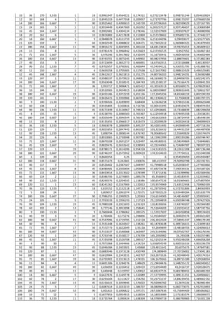
Some Non-standard Rodin step-angles:](https://image.slidesharecdn.com/researchinsolidstatefreeenergygeneratorsver7-5-22-130606180846-phpapp02/85/Research-in-solid-state-free-energy-generators-ver-7-5-22-399-320.jpg)
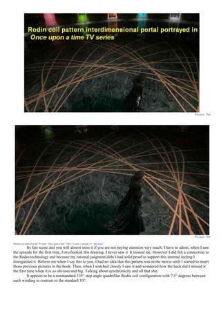
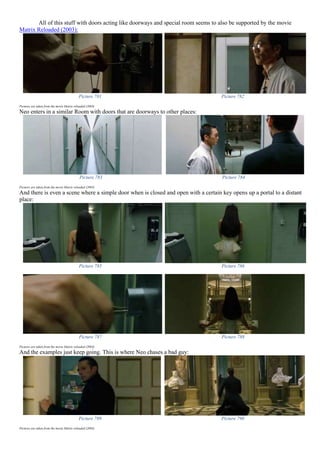
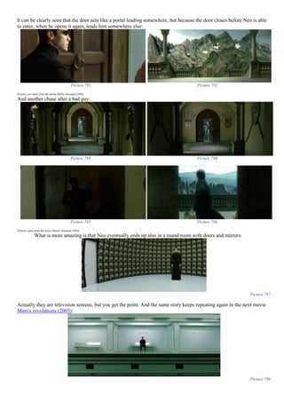
![Picture 766
Now take that! What do you have to say about that?
Nothing. I still think this is absurd and nonsense. It’s just a coincidence. Nothing more. What you are doing
here is called „wishful thinking” and its madness and has nothing to do with a true scientific approach to things. So I
expect you to be serious about this and continue on with the real study of Rodin technology and not these mumbo jumbo
fantasy movies.
Fine then!
Fine!
Interesting to note that all this crap about hats, doors, teleportation and rooms seems to be in tune with other
movies like The Adjustment Bureau (2011). In this movie there’s these guys called the „Adjustment
Bureau” who supervise, observe, adjust, manipulate and change people’s life, events and circumstances when they are
not on their true path dictated by the „Chairman”. These guys all wear some mysterious hats, which just happens to
serve the same purpose of instantaneous travel from two points in space by opening certain doors just like we have
spoken until now.
Picture 767 Picture 768
Pictures are taken from the movie The Adjustment Bureau (2011)
Let me write a partial transcript of some important dialog in the movie:
First of all I’m not going to enter now in too much detail, but going fast very far ahead, water has a major role
in the true real activation of the Rodin technology, as we will see, and since the human mind is a torus at the Holy
Baptism the mind gets activated and a particle accelerated spin will be imprinted on the water inside the pineal gland
“-There's something about water. It blocks our ability to read your decisions. […]
-What if i could move as fast as you? Teach me about the doors.
-The rain will stop in the next hour. That's the only thing keeping them from seeing us right now. If we are going to
do this, we will need all night to do it, and a place surrounded by water to do it in. Always turn the door knob
clockwise […]”
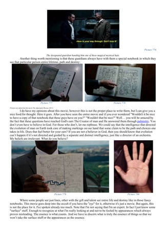
The Adjustment Bureau (2011)](https://image.slidesharecdn.com/researchinsolidstatefreeenergygeneratorsver7-5-22-130606180846-phpapp02/85/Research-in-solid-state-free-energy-generators-ver-7-5-22-414-320.jpg)
![activating it. This seems to interfere with many of the process of correctly reading the memory of someone which is
stored on the charged spheres on the Abha torus. More on that later.
Second, the door knob turning in one correct direction seems to suggest a certain particle spin direction around
a vortex point about which we will also speak later in this book.
Picture 769 Picture 770
Pictures are taken from the movie The Adjustment Bureau (2011)
With the hat on, now all doors are not just doors, but DOORWAYS! Meaning that with these special "hats"
simple doors become doorways or portals of instantaneous travel like we also see in the movie Jumper (2008):
Picture 771 Picture 772 Picture 773
However, in this case, there is a slight difference in how the portals used by jumpers operate. If you watch carefully,
you will realize that they are not actually naturally curving and wrapping space-time, but actually shatter it leaving scars
behind (Picture 773).
Picture 774 Picture 775
This is where the “paladins” prevent the self-healing property of the space-time fabric, by amplifying the
scaring/window/portal left by the “jumpers” so that they too could use the jump portals (Picture 774 and Picture 775).
What seems interesting in Adjustment Bureau, on the other hand, is that they can’t teleport without the hat on
their head. So all the doors are locked:
“-Put your hand on my shoulder and don't let go until we cross the threshold.
-Are these ever locked?
-Not when you are wearing one of our hats. […]
-Even you guys can't get through the doors without your hats on, right?
-Right. It's one of the ways the chairmen limits our power. Water is another way.”
The Adjustment Bureau (2011)](https://image.slidesharecdn.com/researchinsolidstatefreeenergygeneratorsver7-5-22-130606180846-phpapp02/85/Research-in-solid-state-free-energy-generators-ver-7-5-22-415-320.jpg)


![Picture 848
𝑓(𝑠𝑡𝑒𝑝𝑎𝑛𝑔𝑙𝑒) =
2 − √2
{
4 −
1
{
[1 − cos (
𝑠𝑡𝑒𝑝𝑎𝑛𝑔𝑙𝑒
2
)]
2 ∗ [1 + cos(
𝑠𝑡𝑒𝑝𝑎𝑛𝑔𝑙𝑒
2
)]
}
}
=
2 − √2
4 −
2 ∗ [1 + cos (
𝑠𝑡𝑒𝑝𝑎𝑛𝑔𝑙𝑒
2 )]
[1 − cos (
𝑠𝑡𝑒𝑝𝑎𝑛𝑔𝑙𝑒
2 )]
=
2 − √2
2 [2 −
1
tan2 (
𝑠𝑡𝑒𝑝𝑎𝑛𝑔𝑙𝑒
4 )
]
=
𝟐 − √𝟐
𝟐 [𝟐 − 𝒄𝒐𝒕 𝟐 (
𝒔𝒕𝒆𝒑𝒂𝒏𝒈𝒍𝒆
𝟒 )]
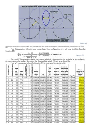
Equation 227
𝑓(150) ≅ 1 Equation 228
Picture 849
Field lines never intersect, however exception being the source point charges of any dipole (they are intersection points). Picture is intended to study geometrical patterns and not field
lines.
I wonder if it's not exactly 1, then what would the step-angle have to be so that the angle condition for the
balanced symmetric Rodin double-spindle-torus be satisfied?
Let's think.
We know we need an angle must be ∠𝑨 = 𝟏𝟔, 𝟑𝟐𝟒𝟗𝟒𝟗𝟗𝟒° from relation (14), so how do we proceed?
We write this:](https://image.slidesharecdn.com/researchinsolidstatefreeenergygeneratorsver7-5-22-130606180846-phpapp02/85/Research-in-solid-state-free-energy-generators-ver-7-5-22-456-320.jpg)
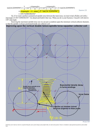
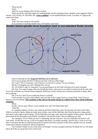
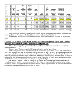
![Again, I only represented the upper spindle torus, for simplicity reasons, but there's two of them. The topology
is a double lemon-spindle torus into one. One field. One. Just that it has the shape of a double torus topology, but it is
one field. One. Not two. Not separated. Nothing like that. It's one unified field.
Note that the central lemon diameter IS NOT EXACTLY:
𝑅 − 𝑟
2
∗ (2 − √2) Equation 230
because that is in an ideal case where we have a step-angle of 149.716984382341°. So then let’s do this:
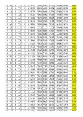
THE RODIN CENTRAL LEMON DIMENSIONS:
Let’s start by drawing this:
Picture 851
Field lines never intersect, however exception being the source point charges of any dipole (they are intersection points). Picture is intended to study geometrical patterns and not field
lines.
Let’s begin with the width of the central lemon or its diameter SU in Picture 851:
|𝑆𝑈| = 2 ∗ |𝑆𝑉| Equation 231
So let’s write:
|𝑆𝐿| − |𝑉𝐿| = |𝑆𝑉| Equation 232
But:
|𝑉𝐿| = |𝑇𝐹| = 𝑟 Equation 233
And:
|𝑆𝐿| = 𝑟𝑐 Equation 234
Because:
|𝑆𝐿| = |𝐿𝐷| = |𝐷𝐸| Equation 235
Where:
r=minor radius in my convention
rc-minor radius in standard convention
Now we substitute Equation 234 and Equation 233 in Equation 232 and we get:
Equation 234, Equation 233 ⟶ Equation 232 ⇒ |𝑆𝑉| = rc − r Equation 236
We know that:
𝑟𝑐 =
𝑅 − 𝑟
2
=
𝑅 − 𝑅 ∗ sin(15°)
2
=
𝑅 ∗ [1 − sin(15°)]
2
Equation 237
And that:
𝑟 = 𝑅 ∗ sin(15°) Equation 238
So now our Equation 236 becomes:](https://image.slidesharecdn.com/researchinsolidstatefreeenergygeneratorsver7-5-22-130606180846-phpapp02/85/Research-in-solid-state-free-energy-generators-ver-7-5-22-458-320.jpg)
![Equation 237
Equation 238
} ⟶ Equation 236 ⟶ Equation 231:
𝐿𝑒𝑚𝑜𝑛 𝑑𝑖𝑎𝑚𝑒𝑡𝑒𝑟 = 2 ∗ [
𝑅 ∗ [1 − sin(15°)]
2
− 𝑅 ∗ sin(15°)]
= 𝑅 ∗ [1 − sin(15°) − 2 ∗ sin(15°)]
Equation 239
So we can write:
𝑹𝒐𝒅𝒊𝒏 𝒄𝒆𝒏𝒕𝒓𝒂𝒍 𝒍𝒆𝒎𝒐𝒏 𝒅𝒊𝒂𝒎𝒆𝒕𝒆𝒓 = 𝑹 ∗ [ 𝟏 − 𝟑 ∗ 𝐬𝐢𝐧(𝟏𝟓°)] Equation 240
However we can also write:
𝑳𝒆𝒎𝒐𝒏 𝒅𝒊𝒂𝒎𝒆𝒕𝒆𝒓 = 𝑹 ∗ [𝐬𝐢𝐧 𝟐(𝟑𝟕, 𝟓°) − 𝐬𝐢 𝐧(𝟏𝟓°)] = 𝑹 ∗ 𝟎, 𝟐𝟐𝟑𝟓𝟒𝟐𝟖𝟔𝟒𝟔𝟗𝟐𝟒𝟑𝟖 Equation 241
Because in Equation 236 rc also equals𝑅 ∗ sin2
(37,5°). But we will stick to the first relation, because in
practical applications, the less advanced functions the better and faster you work with a handheld calculator.
Now let’s take a more difficult task in calculating the Rodin central lemon length (or height) PO in the previous
picture.
When we look at this segment PO we might notice the same thing. It’s made of two equal segments PV and
VO. So we write:
|𝑃𝑂| = |𝑃𝑉| + |𝑉𝑂| = 2 ∗ |𝑃𝑉| Equation 242
Ok. What about segment PV? Well it can be determined from right angle triangle ⊿PVL, because we know VL and PL.
We should calculate the angle PLV because it’s a constant in the perfect Rodin torus:
We apply the cosine trigonometric function on this angle and we write:
cos( 𝑃𝐿𝑉) =
|𝑉𝐿|
|𝑃𝐿|
⟹ 𝑃𝐿𝑉 = arccos (
𝑉𝐿
𝑃𝐿
) Equation 243
However we can easily notice that VL=r and PL equals rc where r is my minor radius and rc is the conventional
minor radius.
So now our angle becomes:
𝑃𝐿𝑉 = arccos(
𝑟
𝑟𝑐
) = arccos [
𝑅 ∗ sin(15°)
𝑅 − 𝑟
2
]
= arccos [
𝑅 ∗ sin(15°)
𝑅 − 𝑅 ∗ sin(15°)
2
]
= arccos {
2 ∗ 𝑅 ∗ sin(15°)
𝑅 ∗ [1 − sin(15°)]
} = arccos[
2 ∗ sin(15°)
1 − sin(15°)
]
= arccos [
2 ∗ sin(15°)
2 ∗ sin2(37,5°)
] = arccos [
sin(15°)
sin2(37,5°)
] = 𝟒𝟓. 𝟕𝟎𝟏𝟓𝟏𝟒𝟎𝟖𝟖𝟏𝟕𝟏𝟕°
Equation 244
Now in the same right angle triangle ⊿PVL we apply this time a sine trigonometric function to get our much
desired PV segment:
𝐼𝑛 𝑟𝑖𝑔ℎ𝑡 𝑎𝑛𝑔𝑙𝑒 ⊿𝑃𝑉𝐿: sin( 𝑃𝐿𝑉) =
|𝑃𝑉|
|𝑃𝐿|
⟹ |𝑃𝑉| = |𝑃𝐿| ∗ sin( 𝑃𝐿𝑉) Equation 245
So considering also Equation 243 we can write:
𝑹𝒐𝒅𝒊𝒏 𝑪𝒆𝒏𝒕𝒓𝒂𝒍 𝒍𝒆𝒎𝒐𝒏 𝒉𝒆𝒊𝒈𝒉𝒕 = 𝟐 ∗ 𝒓 𝒄 ∗ 𝐬𝐢𝐧( 𝟒𝟓. 𝟕𝟎𝟏𝟓𝟏𝟒𝟎𝟖𝟖𝟏𝟕𝟏𝟕°) Equation 246
But I’m not happy with using this decimal angle. I want to express this lemon height/length based on simple
angles. In order to do that it will be useful to write something like this:
𝑅𝑜𝑑𝑖𝑛 𝐶𝑒𝑛𝑡𝑟𝑎𝑙 𝑙𝑒𝑚𝑜𝑛 ℎ𝑒𝑖𝑔ℎ𝑡 = 2 ∗ 𝑅 ∗ sin2
(37,5°) ∗ sin{arccos [
sin(15°)
sin2(37,5°)
]} Equation 247
And since we know that sin(arccos(𝑥)) = √1 − 𝑥2 where x is obviously expressed in radians, since we are not dealing
with complex numbers made with √−1 = 𝑖 or some prefer j (not to be confused with instantaneous value for current),
we can write:](https://image.slidesharecdn.com/researchinsolidstatefreeenergygeneratorsver7-5-22-130606180846-phpapp02/85/Research-in-solid-state-free-energy-generators-ver-7-5-22-459-320.jpg)
![𝑅𝑜𝑑𝑖𝑛 𝐶𝑒𝑛𝑡𝑟𝑎𝑙 𝑙𝑒𝑚𝑜𝑛 ℎ𝑒𝑖𝑔ℎ𝑡 = 2 ∗ 𝑅 ∗ sin2
(37,5°) ∗ √1 − [
sin(15°)
sin2(37,5°)
]
2
= 2 ∗ 𝑅 ∗ sin2
(37,5°) ∗ √1 − [
sin2(15°)
sin4(37,5°)
] = 2 ∗ 𝑅 ∗ sin2
(37,5°)
∗ √
sin4(37,5°) − sin2(15°)
sin4(37,5°)
= 2 ∗ 𝑅 ∗ sin2
(37,5°) ∗
√sin4(37,5°) − sin2(15°)
sin2(37,5°)
= 2 ∗ 𝑅 ∗ √sin4(37,5°) − sin2(15°)
Equation 248
This can be further simplified:
𝑅𝑜𝑑𝑖𝑛 𝐶𝑒𝑛𝑡𝑟𝑎𝑙 𝑙𝑒𝑚𝑜𝑛 ℎ𝑒𝑖𝑔ℎ𝑡 = 2 ∗ 𝑅 ∗ √
[1 − cos(75°)]2
4
−
1 − cos(30°)
2
= 2 ∗ 𝑅 ∗ √
[1 − cos(75°)]2
4
−
1 − cos(30°)
2
= 2 ∗ 𝑅 ∗ √
1 − 2 ∗ cos(75°) + cos2(75°) − 2 + 2 ∗ cos(30°)
4
= 𝑅 ∗ √2 ∗ cos(30°) − 2 ∗ cos(75°) +
1 + cos(150°)
2
− 1
=
𝑅
√2
∗ √4 ∗ cos(30°) − 4 ∗ cos(75°) − 1 + cos(150°)
=
𝑅
√2
∗ √2√3 − √6 + √2 − √3
2
⁄ − 1 =
𝑅
√2
∗ √
4√3 − 2√6 + 2√2 − √3 − 2
2
Equation 249
And we can finally write:
𝑹𝒐𝒅𝒊𝒏 𝑪𝒆𝒏𝒕𝒓𝒂𝒍 𝒍𝒆𝒎𝒐𝒏 𝒉𝒆𝒊𝒈𝒉𝒕 =
𝑹
𝟐
∗ √ 𝟑√𝟑 + 𝟐√𝟐 − 𝟐√𝟔 − 𝟐
= 𝑹 ∗ 𝟎, 𝟓𝟑𝟎𝟒𝟕𝟏𝟓𝟎𝟐𝟗𝟕𝟕𝟖𝟖𝟓
Equation 250
I think I have missed a binomial squared in my calculations, but I’m not very sure. I’m a little rusty, so experienced
readers will have to further simplify this formula if I missed something.
This central lemon is also called “vesica piscis” in sacred geometry. It’s one of the most important sacred
geometric figures also known as “mandorla” which is an aureola surrounding Christ in majesty in early medieval
illuminated manuscripts. A very important descriptive parameter about vesica piscis is the ratio between height and
diameter. In our standard 150 step angle this ratio is 2.373019168863816712886272637337
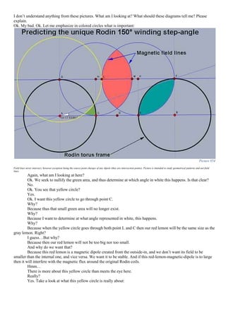
Predicting the unique Rodin 150° winding step-angle
There is another method by which it can be determined that the standard 150° step-angle winding for the Rodin
coil is a unique and special step-angle:
Look at this:
Picture 852 Picture 853](https://image.slidesharecdn.com/researchinsolidstatefreeenergygeneratorsver7-5-22-130606180846-phpapp02/85/Research-in-solid-state-free-energy-generators-ver-7-5-22-460-320.jpg)


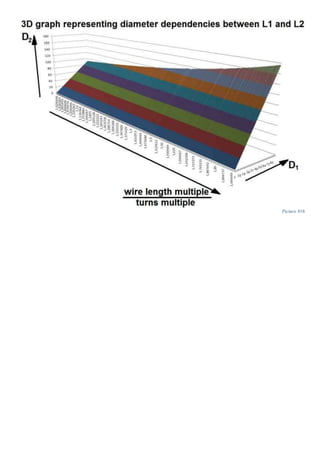
![𝑾 𝑳 𝟐
𝑾 𝑳 𝟏
=
𝟐𝟗𝟒𝟎, 𝟓𝟑𝒎𝒎
𝟒𝟐𝟎. 𝟎𝟕𝒎𝒎
≅ 𝟕 Equation 268
Well, I'll be damned! You really have hit two rabbits with one stone. This is a very important aspect in tuning to
magnetic resonance.
Yes it is. And if you wonder how I did it, it's simple. You think that there are two rabbits…but in fact there is
only one rabbit…but I will speak about that later…
We can do a lot of work around Don Smith double condition for magnetic resonance.
Really? Is there more to say about this?
Yes it is. We have just scratched the surface. Ok. Follow my line of thought. Another important aspect we must
consider, is that in order to maximize the inductive coupling between coil L1 and coil L2, the diameters D1 and D2 must
be close together as possible.
Why? Inductive coupling? Why? It's not an energy transfer! It's just an actuator! You are contradicting yourself.
No. I am not. Please understand that if coil L2 has a diameter D2 of 68mm it's impractical to use an actuator L1
coil with diameter D1 of 7.08 mm. (48/5). It is absurd.
Why?
Because it is damn to small. That's why!
Why?
Because it's like a dog or a cat pushing a huge truck.
You have to be more academic for me to understand.
Ok. Ok. The magnetic field intensity of coil L1 should be large enough to counteract the natural damping factor
in the system. The energy in the actuator field must be greater than the energy loss in the system due to friction and
other losses. Note that the load doesn't affect the double torus magnetic field geometry. So it is eliminated from our
equation of losses in the system.
Ok. Now I get it. So how is this relevant to our table?
It is. Because in order to eliminate this problem for good, it's a good way to wind coil L1 with thick heavy AWG
wire just in case. You never know the energy requirements and also to reduce internal resistance of the coil and thus
increase the Q. Better to be on the safe side, if you know what I mean. Ok. So even if you are actuating with High
voltage and low current, it doesn't hurt to have thick heavy AWG wire in coil L1. And to be really sure you don't have
this under-rating design problem, we should build coil L1 so that it is almost the same diameter as coil L2 but still
capable of sliding inside it, in order to maximize the inductive coupling.
Hmm…ok…good point. How can this be mathematically written?
We could write something like this:
𝐷2
𝐷1
< 2 ⇔
𝑥
𝑦
< 2 Equation 269
Or:
𝑥
𝑦
→ 𝑐𝑙𝑜𝑠𝑒 𝑡𝑜 1 𝑎𝑠 𝑝𝑜𝑠𝑠𝑖𝑏𝑙𝑒 Equation 270
Or:
|𝐷2 − 𝐷1| → 0 𝑏𝑢𝑡 ≠ 0 𝑠𝑖𝑛𝑐𝑒 𝐷2 ≠ 𝐷1 Equation 271
Ok. How can we implement this condition in our table?
Well, let's think about all the possible ratios between x and y in the interval (0.50]. We take 1 with all the
variables till 50, then we take 2 with all the variables till 50, and so on, so we have: 50*50=2500. But under-unity ratios
are not permitted, because x>y (the multiple of wire length must be greater than the multiple of turns). So we reduce
half of these ratios. 2500/2=1250. Now we sort all the valid values in ascending order and we get something like this:](https://image.slidesharecdn.com/researchinsolidstatefreeenergygeneratorsver7-5-22-130606180846-phpapp02/85/Research-in-solid-state-free-energy-generators-ver-7-5-22-508-320.jpg)
![Be very careful with these details! This things matter more than you could possible imagine!!! You will see
later how.
The easiest way is to find two diameters that follow one of these ratios like:
𝑥 + 1
𝑥
, 𝑥 ∈ ℕ+
∗ Equation 272
I believe, that Don Smith searched for a pre-made coil that has a diameter in a perfect ratio with one of the
standard diameters PVC tubes on the market. Once he found a pre-made coil with a diameter of let's say 70mm with 24
turns, then he most likely used such a ratio so that for example he would have used this math:
𝐷2 = 70𝑚𝑚
𝑇2 = 24
; Equation 273
But:
𝑦 =
𝑇2
𝑇1
Equation 274
and:
𝐷2
𝐷1
=
𝑦 + 1
𝑦
⇒
𝐷2
𝐷1
=
𝑇2
𝑇1
+ 1
𝑇2
𝑇1
=
𝑇2 + 𝑇1
𝑇1
∗
𝑇1
𝑇2
⇒ 𝑫 𝟏 =
𝑫 𝟐 ∗ 𝑻 𝟐
𝑻 𝟐 + 𝑻 𝟏
Equation 275
So, if for example he chooses to wind 3 turns in coil L1 then its diameter must be:
𝐷1 =
70𝑚𝑚 ∗ 24
24 + 3
= 62,22𝑚𝑚 Equation 276
Nr of turns in L1 → 1 2 3 4 5 6 7 8 9 10
Diameter of L1 [mm] → 67.2 64.62 62.22 60 57.93 56 54.19 52.5 50.91 49.41
Table 12
Of course then you must take into account the thickness of L1 wire so that the PVC pipe will have the correct
diameter. If not, then we could tweak the number of turns at a decimal number so that we arrive at a certain standard
PVC diameter.
As it can be seen, this can be attacked from many possible angles. And this is just a case among other cases. All
this discussion is when you know the L2 parameters like diameter and turns, but you could start the other way around.
Start from L1 parameters and determine the rest. Again, as it can be seen, this is a very, very, very long story… The only
thing that remains unchanged are the formulas used that determine the rest of the unknown parameters.
We could continue this never ending story by trying to build the coils using frames that you have at your
disposal in your house. Any perfect cylinder could be used as a frame for a coil in replica for a Don Smith device.
However, finding a certain diameter jar or bottle for our frame will be a tedious work, so for some people will seem
more convenient to try and buy a premade coil, but for others will try to make it.
So I will give some help to those in the second group of people who are trying to build the coils from scratch.
What if we could plug in all the frame diameters we have access to in the computer, and let the computer spit
out what particular jars and bottles to use that are in a perfect Don Smith double condition perfect ratio. So for example
I'm interested in saying to the computer:
"Hey! I have these bottles that have these diameters: 45mm and 70mm etc. I also have a jar with the
diameter of 82mm".
Then I want to computer to give me an answer something like this:
"Use the moonshine bottle in your kitchen as frame for L2 and the honey jar in the store as frame for L1.
They are in perfect Smith ratio."
Won't that be cool, or what? Such a program will be cool to have, so let's design one. By the way, I don't have
the habit of drinking, and I don't have a moonshine bottle in my kitchen. It was just an example. You get the picture.
We can write a simple programming code that is capable of such a task. I have chosen to write it in AutoIt -
AutoHotkey:
Here it goes.
#NoEnv
SetBatchLines -1
ListLines Off
V1=984.2519685039370078740157480315
V2=1181.1023622047244094488188976378
V=1082.6771653543307086614173228342
FileDelete, C:diam2.txt
FileDelete, C:diam3.txt
Loop, read, C:diam.txt ;to know how many lines I have](https://image.slidesharecdn.com/researchinsolidstatefreeenergygeneratorsver7-5-22-130606180846-phpapp02/85/Research-in-solid-state-free-energy-generators-ver-7-5-22-511-320.jpg)
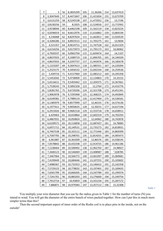
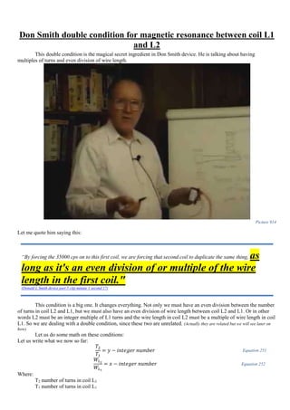
![My point is that in a Smith system we say that the coils L1 and L2 are in magnetic
resonance if this staircase area delimited by the coils are in a perfect ratio.
I don't get it.
Ok. For example the staircase green area delimited by the coil L2 equals 48 mm2
and the staircase green area
delimited by coil L1 equals 12mm2
, their ratio is:
48𝑚𝑚2
12𝑚𝑚2
=
4
1
Equation 278
Or in other words, the area delimited by coil L2 is exactly 4 times bigger than the area of coil L1.
Hmm…. Interesting….
Picture 919
Let's test this condition and the formula for this green staircase area in a few examples. Let's see what we get:
Input variables Output parameters
D2
[mm]
T2
[turns
] x/y
height L2
[mm]
D1
[mm]
T1
[turns]
WL1
[mm]
WL2
[mm]
WL2/
WL1
pitch L1
[mm]
pitch L2
[mm]
Area L1
[mm2
]
Area L2
[mm2
]
Area
L2/Area
L1
simple
area L1
simple
area L2 L2/L1
50 20
10/
03
71.59258
263 15
6.66666
6667
314.159
2654
3141.59
2654 10 1
3.57962
9131
1178.362
593
39280.10
9 33.334484
1178.097
245
39269.90
817
33.3333
3333
54 20
05/
04
77.31998
924 43.2 5
678.584
0132
3392.92
0066 5 1
3.86599
9462
7328.906
294
45816.31
913
6.2514538
04
7328.707
342
45804.42
089 6.25
54 20
19/
18
77.31998
924
51.1578
9474
1.11111
1111
178.574
7403
3392.92
0066 19 1
3.86599
9462
2283.921
153
45816.31
913
20.060376
9
2283.876
942
45804.42
089
20.0555
5556
Table 13
Where:
D2 diameter of coil L2 in mm
T2 number of turns in coil L2
x/y Smith double condition ratio](https://image.slidesharecdn.com/researchinsolidstatefreeenergygeneratorsver7-5-22-130606180846-phpapp02/85/Research-in-solid-state-free-energy-generators-ver-7-5-22-517-320.jpg)
![height of the coil L2 expressed in mm
D1 diameter of coil L1 =A3/(VALUE(LEFT(C3;2))/VALUE(RIGHT(C3;2)))
T1 number of turns in coil L1 =B3/VALUE(RIGHT(C3;2))
WL1 total wire length of coil L1 =E3*PI()*F3
WL2 total wire length of coil L2 =A3*PI()*B3
WL2/WL1 ratio of wire lengths =H3/G3
Pitch L1 distance between two consecutive turns in coil L1 expressed in mm
Pitch L2 distance between two consecutive turns in coil L2 expressed in mm =D3/B3
Staircase Area of coil L1 expressed in mm2
=(PI()*POWER((E3/2);2)*F3)/SQRT(1-POWER(J3/(2*PI()*(E3/2));2))
Staircase Area of coil L2 expressed in mm2
=(PI()*POWER(A3/2;2)*B3)/SQRT(1-POWER(K3/(2*PI()*(A3/2));2))
Ratio of the two staircase areas =M3/L3
Simple area of the coil L1 calculated as a simple planar area [mm2
] =(PI()*E3*E3*F3)/4
Simple area of the coil L2 calculated as a simple planar area [mm2
] =(PI()*A3*A3*B3)/4
L2/L1 ratio of simple area coil L1 and simple area coil L2 =P3/O3
Our area ratio doesn't seem to be in a perfect ratio in all cases. We seem to have found an example in the last
third case where we are almost at a multiple of 20 of surface area between coil L1 and coil L2 but the ratio 19/18 seem a
little too big for my taste. If for example I choose to wind 4 turns in coil L1 I hate the fact that I will have to wind
4*18=72 turns in coil L2. Don't you?
So I don't like all these results. I want something good. I want to see all the valid Smith ratios that also generate
perfect area ratios! That's what I want!
Ok then. This is what I'm interested:
ratio
value
x
y
area
areareminder
x-y
ratio
value
x
y
area
areareminder
x-y
ratio
value
x
y
area
areareminder
x-y
ratio
value
x
y
area
areareminder
x-y
ratio
value
x
y
area
areareminder
x-y
'2/1
2
2
1
4
0
1
'24/12
2
24
12
48
0
12
'21/1
21
21
1
441
0
20
'35/5
7
35
5
245
0
30
'44/1
44
44
1
1936
0
43
'6/4
1.5
6
4
9
0
2
'21/9
2.33
21
9
49
0
12
'42/21
2
42
21
84
0
21
'34/4
8.5
34
4
289
0
30
'48/4
12
48
4
576
0
44
'4/2
2
4
2
8
0
2
'20/8
2.5
20
8
50
0
12
'30/9
3.33
30
9
100
0
21
'33/3
11
33
3
363
0
30
'46/2
23
46
2
1058
0
44
'3/1
3
3
1
9
0
2
'18/6
3
18
6
54
0
12
'28/7
4
28
7
112
0
21
'32/2
16
32
2
512
0
30
'45/1
45
45
1
2025
0
44
'12/9
1.33
12
9
16
0
3
'16/4
4
16
4
64
0
12
'24/3
8
24
3
192
0
21
'31/1
31
31
1
961
0
30
'50/5
10
50
5
500
0
45
'6/3
2
6
3
12
0
3
'15/3
5
15
3
75
0
12
'22/1
22
22
1
484
0
21
'32/1
32
32
1
1024
0
31
'48/3
16
48
3
768
0
45
'4/1
4
4
1
16
0
3
'14/2
7
14
2
98
0
12
'44/22
2
44
22
88
0
22
'48/16
3
48
16
144
0
32
'46/1
46
46
1
2116
0
45
'20/16
1.25
20
16
25
0
4
'13/1
13
13
1
169
0
12
'33/11
3
33
11
99
0
22
'40/8
5
40
8
200
0
32
'50/4
12.5
50
4
625
0
46
'12/8
1.5
12
8
18
0
4
'26/13
2
26
13
52
0
13
'26/4
6.5
26
4
169
0
22
'36/4
9
36
4
324
0
32
'48/2
24
48
2
1152
0
46
'8/4
2
8
4
16
0
4
'14/1
14
14
1
196
0
13
'24/2
12
24
2
288
0
22
'34/2
17
34
2
578
0
32
'47/1
47
47
1
2209
0
46
'6/2
3
6
2
18
0
4
'42/28
1.5
42
28
63
0
14
'23/1
23
23
1
529
0
22
'33/1
33
33
1
1089
0
32
'48/1
48
48
1
2304
0
47
'5/1
5
5
1
25
0
4
'28/14
2
28
14
56
0
14
'46/23
2
46
23
92
0
23
'44/11
4
44
11
176
0
33
'50/2
25
50
2
1250
0
48
'30/25
1.2
30
25
36
0
5
'21/7
3
21
7
63
0
14
'24/1
24
24
1
576
0
23
'42/9
4.67
42
9
196
0
33
'49/1
49
49
1
2401
0
48
'10/5
2
10
5
20
0
5
'18/4
4.5
18
4
81
0
14
'48/24
2
48
24
96
0
24
'36/3
12
36
3
432
0
33
'50/1
50
50
1
2500
0
49
'6/1
6
6
1
36
0
5
'16/2
8
16
2
128
0
14
'42/18
2.33
42
18
98
0
24
'34/1
34
34
1
1156
0
33
'50/49
1.02
50
49
51
0.02
1
'42/36
1.17
42
36
49
0
6
'15/1
15
15
1
225
0
14
'40/16
2.5
40
16
100
0
24
'38/4
9.5
38
4
361
0
34
'49/48
1.02
49
48
50
0.02
1
'24/18
1.33
24
18
32
0
6
'40/25
1.6
40
25
64
0
15
'36/12
3
36
12
108
0
24
'36/2
18
36
2
648
0
34
'48/47
1.02
48
47
49
0.02
1
'18/12
1.5
18
12
27
0
6
'30/15
2
30
15
60
0
15
'33/9
3.67
33
9
121
0
24
'35/1
35
35
1
1225
0
34
'47/46
1.02
47
46
48
0.02
1
'15/9
1.67
15
9
25
0
6
'24/9
2.67
24
9
64
0
15
'32/8
4
32
8
128
0
24
'42/7
6
42
7
252
0
35
'46/45
1.02
46
45
47
0.02
1
'12/6
2
12
6
24
0
6
'20/5
4
20
5
80
0
15
'30/6
5
30
6
150
0
24
'40/5
8
40
5
320
0
35
'45/44
1.02
45
44
46
0.02
1
'10/4
2.5
10
4
25
0
6
'18/3
6
18
3
108
0
15
'28/4
7
28
4
196
0
24
'36/1
36
36
1
1296
0
35
'44/43
1.02
44
43
45
0.02
1
'9/3
3
9
3
27
0
6
'16/1
16
16
1
256
0
15
'27/3
9
27
3
243
0
24
'48/12
4
48
12
192
0
36
'43/42
1.02
43
42
44
0.02
1
'8/2
4
8
2
32
0
6
'48/32
1.5
48
32
72
0
16
'26/2
13
26
2
338
0
24
'45/9
5
45
9
225
0
36
'42/41
1.02
42
41
43
0.02
1
'7/1
7
7
1
49
0
6
'32/16
2
32
16
64
0
16
'25/1
25
25
1
625
0
24
'44/8
5.5
44
8
242
0
36
'41/40
1.03
41
40
42
0.02
1
'14/7
2
14
7
28
0
7
'24/8
3
24
8
72
0
16
'50/25
2
50
25
100
0
25
'42/6
7
42
6
294
0
36
'49/40
1.23
49
40
60
0.02
9
'8/1
8
8
1
64
0
7
'20/4
5
20
4
100
0
16
'30/5
6
30
5
180
0
25
'40/4
10
40
4
400
0
36
'40/39
1.03
40
39
41
0.03
1
'40/32
1.25
40
32
50
0
8
'18/2
9
18
2
162
0
16
'26/1
26
26
1
676
0
25
'39/3
13
39
3
507
0
36
'39/38
1.03
39
38
40
0.03
1
'24/16
1.5
24
16
36
0
8
'17/1
17
17
1
289
0
16
'39/13
3
39
13
117
0
26
'38/2
19
38
2
722
0
36
'38/37
1.03
38
37
39
0.03
1
'16/8
2
16
8
32
0
8
'34/17
2
34
17
68
0
17
'30/4
7.5
30
4
225
0
26
'37/1
37
37
1
1369
0
36
'37/36
1.03
37
36
38
0.03
1
'12/4
3
12
4
36
0
8
'18/1
18
18
1
324
0
17
'28/2
14
28
2
392
0
26
'38/1
38
38
1
1444
0
37
'36/35
1.03
36
35
37
0.03
1
'10/2
5
10
2
50
0
8
'45/27
1.67
45
27
75
0
18
'27/1
27
27
1
729
0
26
'42/4
10.5
42
4
441
0
38
'41/35
1.17
41
35
48
0.03
6
'9/1
9
9
1
81
0
8
'36/18
2
36
18
72
0
18
'36/9
4
36
9
144
0
27
'40/2
20
40
2
800
0
38
'35/34
1.03
35
34
36
0.03
1](https://image.slidesharecdn.com/researchinsolidstatefreeenergygeneratorsver7-5-22-130606180846-phpapp02/85/Research-in-solid-state-free-energy-generators-ver-7-5-22-518-320.jpg)
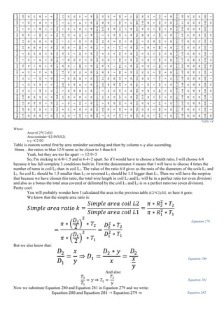
![𝑆𝑖𝑚𝑝𝑙𝑒 𝑎𝑟𝑒𝑎 𝑟𝑎𝑡𝑖𝑜 𝑘 =
𝐷2
2
∗ 𝑇2
(
𝐷2
𝑥
𝑦 )
2
∗ 𝑇2
𝑦
=
𝐷2
2
∗ 𝑇2
𝐷2
2
∗ 𝑦2
𝑥2 ∗ 𝑇2
𝑦
=
𝐷2
2
∗ 𝑇2
𝐷2
2
∗ 𝑦 ∗ 𝑇2
𝑥2
𝑘 =
𝐷2
2
∗ 𝑇2 ∗ 𝑥2
𝐷2
2
∗ 𝑦 ∗ 𝑇2
=
𝑥2
𝑦
Equation 283
We want this variable k to be close to an integer as possible.
𝑘 ∈ ℕ+
∗
Input variables Output parameters
D2 [mm]
T2
[turns]
x+1/x
height
L2
D1
[mm]
T1
[turns]
T2/T1
WL1
[mm]
WL2
[mm]
WL2/WL1
pitch
L1
[mm]
pitch
L2
[mm]
Area L1
[mm2]
Area L2
[mm2]
Area L2
/Area
L1
simple
area L1
simple
area L2
L2/L1
50 20 06/04 71.59 33.33 5 4 523.6 3141.59 6 1 3.5796 4363.52 39280.1 9.00193 4363.32 39269.9 9
50 10 06/04 71.59 33.33 2.5 4 261.8 1570.8 6 1 7.1593 2181.76 19655.4 9.00895 2181.66 19635 9
50 5 06/04 71.59 33.33 1.25 4 130.9 785.398 6 1 14.319 1090.88 9858.52 9.03721 1090.83 9817.48 9
45 20 06/04 64.43 30 5 4 471.24 2827.43 6 2 3.2217 3535.09 31816.9 9.00031 3534.29 31808.6 9
45 10 06/04 64.43 30 2.5 4 235.62 1413.72 6 3 6.4433 1768.04 15920.9 9.0048 1767.15 15904.3 9
45 5 06/04 64.43 30 1.25 4 117.81 706.858 6 4 12.887 884.37 7985.4 9.02948 883.573 7952.16 9
40 20 06/04 57.27 26.67 5 4 418.88 2513.27 6 5 2.8637 2797.51 25139.3 8.98629 2792.53 25132.7 9
40 10 06/04 57.27 26.67 2.5 4 209.44 1256.64 6 6 5.7274 1399.86 12579.4 8.98623 1396.26 12566.4 9
40 5 06/04 57.27 26.67 1.25 4 104.72 628.319 6 7 11.455 700.582 6309.45 9.00602 698.132 6283.19 9
35 20 06/04 50.11 23.33 5 4 366.52 2199.11 6 8 2.5057 2150.88 19247.3 8.94857 2138.03 19242.3 9
35 10 06/04 50.11 23.33 2.5 4 183.26 1099.56 6 9 5.0115 1077.16 9631.14 8.9412 1069.01 9621.13 9
35 5 06/04 50.11 23.33 1.25 4 91.63 549.779 6 10 10.023 539.551 4830.68 8.95314 534.507 4810.56 9
30 20 06/04 42.96 20 5 4 314.16 1884.96 6 11 2.1478 1595.44 14140.8 8.8633 1570.8 14137.2 9
30 10 06/04 42.96 20 2.5 4 157.08 942.478 6 12 4.2956 800.126 7075.94 8.84353 785.398 7068.58 9
30 5 06/04 42.96 20 1.25 4 78.54 471.239 6 13 8.5911 401.384 3549.07 8.84207 392.699 3534.29 9
Table 15
A slight different working principle behind Don Smith device
Wait, I thought you have presented the working principle. Why are you talking about another?
Listen. I don't claim anything. I am not that person who hits with his fist on the table saying: "It is this way!”
No. I am not like that.
Ok. But ten why are you presenting a different working principle? Does this mean that the previous is wrong?
No. In my eyes they are both correct. But in the eyes of the reader it will probably not. However there are slight
differences. So it is just as I said. I am the junkyard keeper. If you like the way I envision the working principle, fine.
Take it, assume it's yours, tell everybody what a new idea you have about Don Smith or Rodin coil, or whatever device
you like. I don't care. If you don't like what I'm saying, then don't read. My motto in life is if you don't like something,
then don't look. Nobody is forcing you do to something. Free will is our most precious gift from our Creator. I'm just a
simple average Joe, who collects thoughts, idea, garbage, gold nuggets (just because they are shiny stones, not because I find them valuable),
junks, bullshits, and all sorts of crap. All jumbled together in this junkyard of a book. If you think something is
valuable. Fine. Take it. It's yours. I don't care. You take whatever you want. Assume it's yours. I don't care. I'm
irrelevant. The messenger is not important. It is the message that is valuable. If you like the message, fine. Take it. If
you don't then don't listen and don't look. Nobody is forcing anybody here.
Wait. You are the messenger? What that makes you? Moses with the tablets?
Look. I already told you that I'm nobody. If you can't accept that, then just
label me "The Junkyard keeper" and go on with it. I speak a lot of gibberish anyway.
You are selling yourself a little too short, don’t you think?
Oh, no!...No, no, no…No! You are mistaken. I’m not selling myself at all!
You got it all wrong!
I don’t follow…
I’m not after selling myself, I’m in fact giving myself freely, no charge, no
cost, nothing. I seek a pure exacerbation of altruism.
Picture 920 this is how I see this book](https://image.slidesharecdn.com/researchinsolidstatefreeenergygeneratorsver7-5-22-130606180846-phpapp02/85/Research-in-solid-state-free-energy-generators-ver-7-5-22-520-320.jpg)
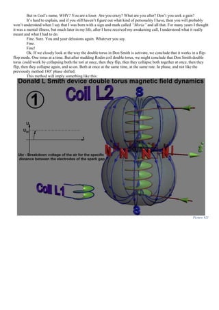
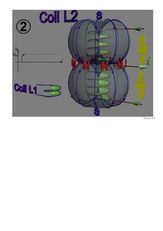
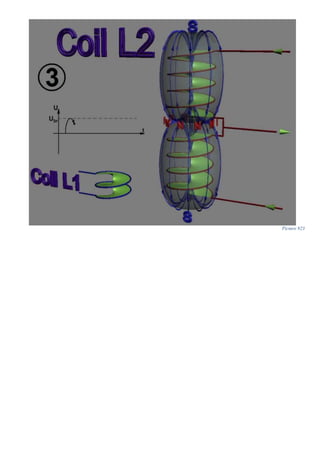
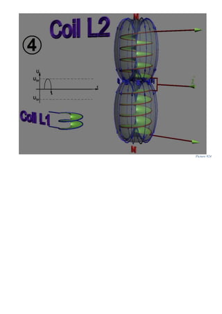
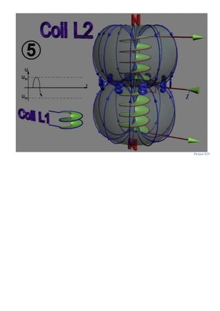
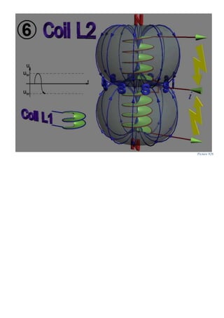
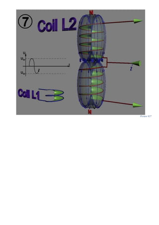
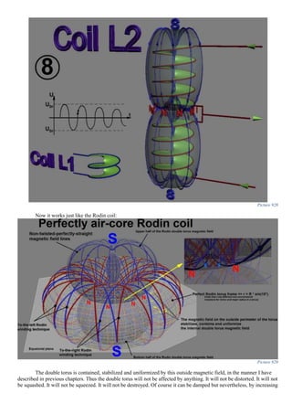
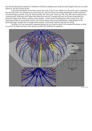
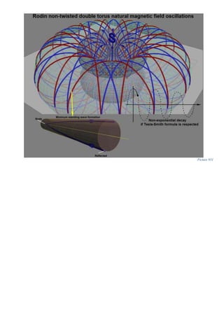
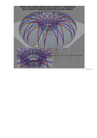
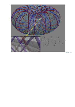
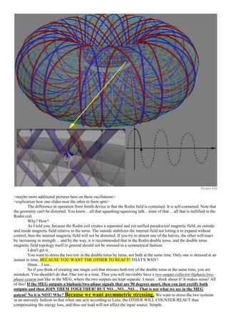
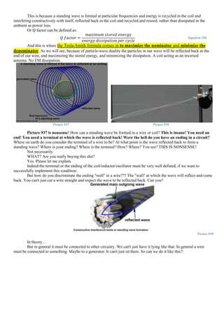
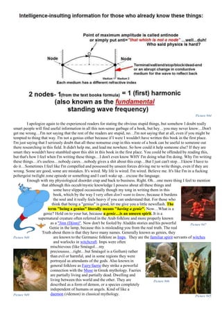
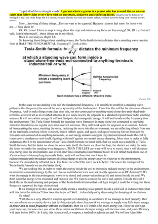
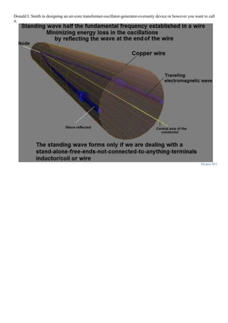
![insulation material around the wire. Trying to figure out exactly the value for such a refractive index for different
insulation materials is extremely difficult since it majorly depends on the wavelength we are using. For example the
refractive index for a material has a different value for red light than it has for violet light. However the energy in our
device doesn’t approach visible light EM radiation, because if it were so, we would see the wires glow, and that is
absurd of course. Therefore let’s stick to things we do know for a fact.
We know for a fact that in a LC tank circuit the resonant frequency is determined by:
𝑓𝐿𝐶 [𝐻𝑧] =
1
2𝜋√ 𝐿[𝐻] 𝐶[𝐹]
Equation 294
Where:
FLC-resonant frequency of our LC tank circuit expressed in Hertz;
L – Inductance value of our coil expressed in Henrys;
C- Capacitance value of our capacitor expressed in Farads;
We also know that Tesla recommends using this formula in oscillating inductors:
𝑓𝑇𝑒𝑠𝑙𝑎[𝐻𝑧] =
𝑐 [ 𝑚
𝑠⁄ ]
4 ∗ 𝑙 [𝑚]
Equation 295
Where:
Ftesla-frequency dictated by Tesla-Smith formula to establish standing wave patterns in stand-alone-not-connected-to-anything-free-ends-open-terminals inductors expressed in Hertz;
c-speed of light in the conductive medium of the wire our inductor is made of (Copper, aluminum or whatever we use) expressed in meters per second;
l – the total length of our wire that makes up our coil expressed in meters;
What we need to do is to make these two separated and apparent different formulas together. Thus we bring the
magnetic resonance with LC resonance together. I know, I know. I make a very confusing overlapping of terms when I
refer to “magnetic resonance” with that concept when we researched VTA magnetic resonance.
My response to this apparent confusion is that if you were able to bring Donald L. Smith and Floyd Sparky
Sweet together face to face, they will definitely disagree and argue on this term as “magnetic resonance”. I have heard
Smith speaking of magnetic resonance in his device, but I believe he refers to something different than Sweet is talking
about. I believe that Floyd Sparky Sweet concept of “magnetic resonance” is much closer to the real concept of
“magnetic resonance”
From all of my studies I believe that the true concept of “magnetic resonance” is something very different from
what I have described in this book, which is majorly connected to quantum physics, atomic moment, Bohr magneton
and all that. However, we will not speak about that in this book, because for one it’s a little beyond my area of expertise
and it’s not the subject of this book.
To make it short and end this confusion, I will say that it’s just wording. That’s all. Just words. I don’t see why
anybody should argue and fight about just because they believe that something has a different name. Personally I
believe it’s the most foolish thing to do. There was too much blood spilled on this Earth in the true name of God, either
it’s Allah or Yahweh. Instead of coming together and ask ourselves how we can both be right we pull out the sword. So
many disagreements between men just because we don’t use the proper words. This is such a sad situation. They are just
words. It is the fundamental unspoken idea that is important here. It is understanding. Not words. Words are irrelevant.
They are just a means, just a tool. Equations, numbers, formulas, these never lie. Mathematics is a universal language of
nature. If we can’t make ourselves understood through words then let’s use a more transcendental language as
mathematics.
Ok. So let’s take this crucial piece of data about LC resonance and standing waves and place the…](https://image.slidesharecdn.com/researchinsolidstatefreeenergygeneratorsver7-5-22-130606180846-phpapp02/85/Research-in-solid-state-free-energy-generators-ver-7-5-22-544-320.jpg)
![CORNERSTONE
OF THE DON
SMITH DEVICE
𝟏
𝟐𝝅√ 𝑳[𝑯] 𝑪[𝑭]
= 𝒌
𝒄 [ 𝒎
𝒔⁄ ]
𝟒 ∗ 𝒍 [𝒎]
Equation 296
Smith LC
standing
wave
Where:
L – Inductance value of our coil expressed in Henrys;
C- Capacitance value of our capacitor expressed in Farads;
k-integer natural positive constant different from 0 like 1, 2, 3, 4, 5 etc. adimensional;
c-speed of light in the conductive medium of the wire our inductor is made of (Copper, aluminum or whatever we use) expressed in meters per second;
l – the total length of our wire that makes up our coil expressed in meters;
This is a monumental formula. It lies at the core
principle of Don Smith device! I don’t understand why those who have successfully
replicated Don Smith device are not talking about it. And I ask now the excruciating painful question: WHY?
IN GOD’S NAME, WHY???
You can’t even begin to understand the pain I’m going through right now…Sadly, God is not answering my
question…maybe someday I will find out the answer to this question…maybe…just maybe…
Let’s work with this formula a little and determine the inductance.
Wait, you are confusing me, I thought we were talking about determining the capacitance value for the
capacitor in our Don Smith device. Why do you say now that we have to calculate the inductance?
Patience, my friend, patience. We will get there. Look at what I’m doing and understand:
1
2𝜋√ 𝐿[𝐻] 𝐶[𝐹]
=
𝑐 [ 𝑚
𝑠⁄ ]
4 ∗ 𝑙 [𝑚]
|
2
⟺
1
4𝜋2 𝐿[𝐻] 𝐶[𝐹]
=
𝑘2
∗ 𝑐2[ 𝑚
𝑠⁄ ]
16 ∗ 𝑙2 [𝑚]
Equation 297
Now let’s extract the inductance:
𝐿[𝐻] =
16 ∗ 𝑙2
[𝑚]
𝑐2[ 𝑚
𝑠⁄ ] ∗ 4𝜋2 ∗ 𝐶[𝐹]
=
4 ∗ 𝑙2
[𝑚]
𝑘2 ∗ 𝑐2[ 𝑚
𝑠⁄ ] ∗ 𝜋2 ∗ 𝐶[𝐹]
Equation 298
Now, let’s think about this little l. What is it?
It’s the total length of our wire in our coil expressed in meters.
True, but what does it equals to?
Well…
Think about it! Remember that we are using standard basic single-layer helical round wire coil inductor,
therefore its length will be:](https://image.slidesharecdn.com/researchinsolidstatefreeenergygeneratorsver7-5-22-130606180846-phpapp02/85/Research-in-solid-state-free-energy-generators-ver-7-5-22-545-320.jpg)
![𝑇𝑜𝑡𝑎𝑙 𝑙𝑒𝑛𝑔ℎ𝑡 𝑜𝑓 𝑜𝑢𝑟 𝑤𝑖𝑟𝑒 (𝑙)[𝑚] = 𝜋 ∗ 𝑑 [𝑚] ∗ 𝑛 Equation 299
Where:
d-diameter of our coil expressed in meters;
n-number of turns in our coil adimensional;
What we have just done is determined the length of our wire by calculating the length of one turn (which is the
circumference of the circle (2πR=2D)) and then multiplied this by the number of turn. Simple.
Note that when we have a relative large winding pitch such a formula will not be very accurate, and direct measurement of the wire before creating our coil may be required.
Now let’s rewrite our final inductance formula for the Smith device cornerstone:
𝐿[𝐻] =
4 ∗ ( 𝜋 ∗ 𝑑 [𝑚] ∗ 𝑛)2
𝑘2 ∗ 𝑐2[ 𝑚
𝑠⁄ ] ∗ 𝜋2 ∗ 𝐶[𝐹]
=
4 ∗ 𝑑2
[ 𝑚] ∗ 𝑛2
𝑘2 ∗ 𝑐2[ 𝑚
𝑠⁄ ] ∗ 𝐶[𝐹]
Equation 300
Where:
L – Inductance value of our coil expressed in Henrys;
d-diameter of our coil expressed in meters;
n-number of turns in our coil adimensional;
k-integer natural positive constant different from 0like 1, 2, 3, 4, 5 etc. adimensional;
c-speed of light in the conductive medium of the wire our inductor is made of (Copper, aluminum or whatever we use) expressed in meters per second;
C- Capacitance value of our capacitor expressed in Farads;
Ok. Now let’s write the Wheeler's inductance formula for standard basic single-layer helical round wire coil
inductor:
𝐿[µ𝐻] =
𝑑2[𝑚] ∗ 𝑛2
𝑙𝑒𝑛[𝑚] + 0,45 ∗ 𝑑[𝑚]
| ∗ (10−6
) ⟺ 𝐿[𝐻] =
𝑑2[𝑚] ∗ 𝑛2
(𝑙𝑒𝑛[𝑚] + 0,45 ∗ 𝑑[𝑚]) ∗ (106)
Equation 301
Where:
L – Inductance value of our coil expressed in Henrys;
d-diameter of our coil expressed in meters;
n-number of turns in our coil adimensional;
len-length of our coil from one terminal to the other (note that is not the total length of the wire, that is why I named it “len” so that it will not be confused with l. It is expressed in meters;
Note that this formula only holds when len≥0.4d, meaning it’s valid only for “long coils” which pretty much means that
is valid when we apply it for our Don Smith coil.
Now let’s see what this Smith cornerstone is made of by writing:
4 ∗ 𝑑2[𝑚] ∗ 𝑛2
𝑘2
∗ 𝑐2[ 𝑚
𝑠⁄ ] ∗ 𝐶[𝐹]
=
𝑑2[𝑚] ∗ 𝑛2
(𝑙𝑒𝑛[𝑚] + 0,45 ∗ 𝑑[𝑚]) ∗ (106)
Equation 302
Now that we have finally got rid of inductance in our Smith cornerstone formula let’s calculate our much
desired capacitor value:
𝐶[𝐹] =
106
∗ (𝑙𝑒𝑛[𝑚] + 0,45 ∗ 𝑑[𝑚]) ∗ 4 ∗ 𝑑2[𝑚] ∗ 𝑛2
𝑑2[𝑚] ∗ 𝑛2 ∗ 𝑘2
∗ 𝑐2[ 𝑚
𝑠⁄ ]
⟹ Equation 303
DON SMITH DEVICE CAPACITOR VALUE FORMULA
𝑪[𝑭] =
𝟒 ∗ 𝟏𝟎 𝟔
∗ ( 𝒍𝒆𝒏[ 𝒎] + 𝟎, 𝟒𝟓 ∗ 𝒅[𝒎])
𝒌 𝟐 ∗ 𝒄 𝟐[ 𝒎
𝒔⁄ ]
Equation
304
Where:
C- Capacitance value of our capacitor expressed in Farads;
len-length of our coil from one terminal to the other (note that is not the total length of the wire, that is why I named it “len” so that it will not be confused with l. It
is expressed in meters;
d-diameter of our coil expressed in meters;
k-integer natural positive constant different from 0like 1, 2, 3, 4, 5 etc. adimensional;
c-speed of light in the conductive medium of the wire our inductor is made of (Copper, aluminum or whatever we use) expressed in meters per second;
Picture 953
Again you might ask how the capacitor value can be variable if we have this k at the denominator. My answer
is…actually I already have addressed this issue, but here I go again. The reason is because the resonant LC frequency
can be set on theoretical any harmonic of our standing wave pattern. It is recommended for maximum efficiency that](https://image.slidesharecdn.com/researchinsolidstatefreeenergygeneratorsver7-5-22-130606180846-phpapp02/85/Research-in-solid-state-free-energy-generators-ver-7-5-22-546-320.jpg)

![The thing that the experienced readers will quickly start to cling on, it that I’m wrong in these picture because I
totally ignore the coupling factor between the coils, and I disregard the mutual inductance.
Ok. My response is: No. I am not. The mutual inductance basically is how much a coil influences the other coil.
In other terms is how much of the magnetic field of coil A cuts the wires of coil B. The mutual inductance is determined
by this formula:
𝑀[𝐻] = 𝑘 ∗ √ 𝐿2𝑎 ∗ 𝐿2𝑏 Equation 305
Where:
M-is the mutual inductance expressed in henrys;
k-is the coefficient of coupling between the coils adimensional (between 0 and 1);
La and Lb are the inductances of the two coils expressed in henrys;
How does this mutual inductance comes into play in all of this?
Well it is required to take it into account in our case when calculating series and parallel total inductance.
For example. The experienced readers will say that I’m wrong and that the total inductance of this circuit:
Picture 956
is according to the text books actually:
𝐿 𝑡𝑜𝑡𝑎𝑙 =
𝐿2𝑎 ∗ 𝐿2𝑏 − 𝑀2
𝐿2𝑎 + 𝐿2𝑏 − 2𝑀
Equation 306
Now if L2a=L2b which it does, since it is how the Don Smith device is really constructed, then the text-book formula
for the parallel equivalent total inductance will now become:
𝐿 𝑡𝑜𝑡𝑎𝑙 =
(𝐿2𝑎)2
− 𝑀2
2 ∗ 𝐿2𝑎 − 2𝑀
=
(𝐿2𝑎 + 𝑀)(𝐿2𝑏 − 𝑀)
2 ∗ (𝐿2𝑏 − 𝑀)
=
𝐿2𝑎 + 𝑀
2
Equation 307
So. Let’s now calculate this mutual inductance M.
If we take a closer look, at the formula for M:
𝑀[𝐻] = 𝑘 ∗ √ 𝐿2𝑎 ∗ 𝐿2𝑏 Equation 308
We will realize that it’s all about this k factor which is the coupling coefficient. But how can we determine this k? What
is it made of?
The answer is that the coefficient of coupling, k is at maximum value - equal to 1, (unity) when all the lines of
flux of one coil cuts all of the turns of the other coil. And corollary, when the coupling coefficient k is at minimum
value 0, (zero) then all the lines of flux of one coil never touches or cuts, or crosses the turns of the other coil.
Hmm....So, then how can we determine the coupling coefficient k in our Don Smith device case?
Let’s remember how our double torus magnetic field geometry/topology looks like:](https://image.slidesharecdn.com/researchinsolidstatefreeenergygeneratorsver7-5-22-130606180846-phpapp02/85/Research-in-solid-state-free-energy-generators-ver-7-5-22-549-320.jpg)
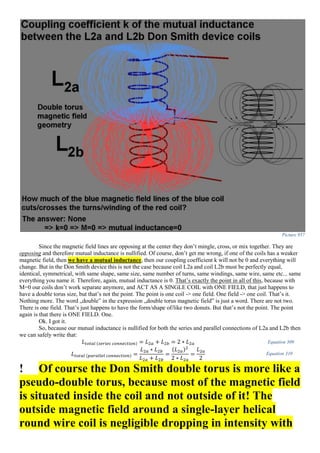
![Picture 960
Picture 961
Picture 962
which is exactly what I have here on the blackboard. It has 2800 windings. We are going to run a current which is
something like 4.5 Amperes and I’m going to tell you what that current is, because I have a current meter there for you
and I also have a meter which indicates the magnetic field. The lower one is the current meter. And the maxim current
you see there as 3 will be 6 amperes. The upper one it’s calibrated in such a way that its full scale 3 we would have 300
Gauss. I have a magnetic Hall probe which allows me to measure the magnetic field in the vicinity of this solenoid. […]
and evaluate the magnetic field near the opening of the solenoid. Then we can go in there and then we can also probe
the outside.](https://image.slidesharecdn.com/researchinsolidstatefreeenergygeneratorsver7-5-22-130606180846-phpapp02/85/Research-in-solid-state-free-energy-generators-ver-7-5-22-552-320.jpg)
![Picture 963
It’s a little higher than I previously assumed. And here it comes this probe. I am now a foot away from the entrance and
you see nothing.
Picture 964 Picture 965
Picture 966 Picture 967
Amazing! And when I come out here, I move it back and forth about 20 cm [and is still constant] […]](https://image.slidesharecdn.com/researchinsolidstatefreeenergygeneratorsver7-5-22-130606180846-phpapp02/85/Research-in-solid-state-free-energy-generators-ver-7-5-22-553-320.jpg)
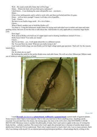
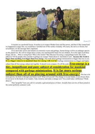
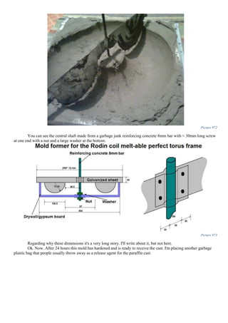
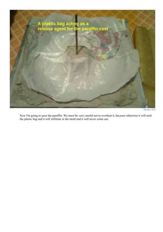
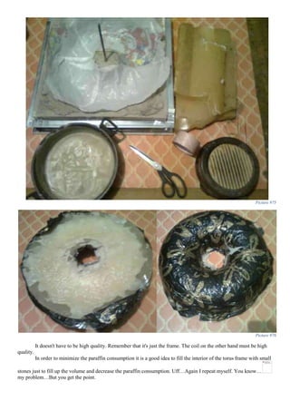
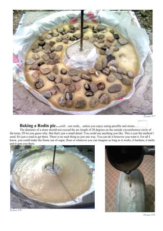
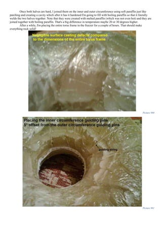

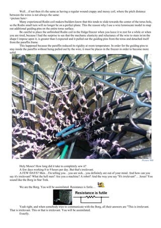
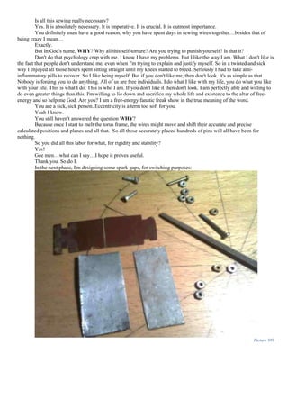
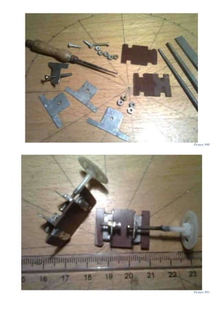
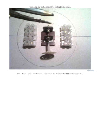
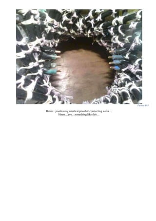
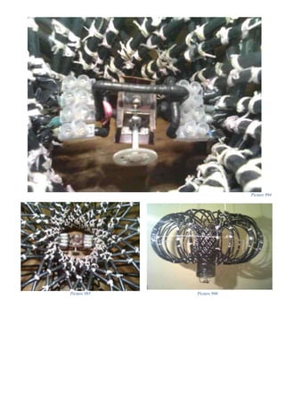
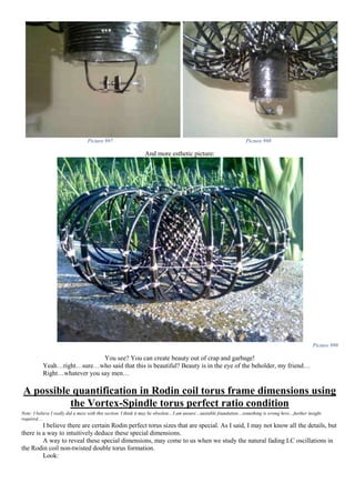
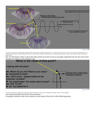
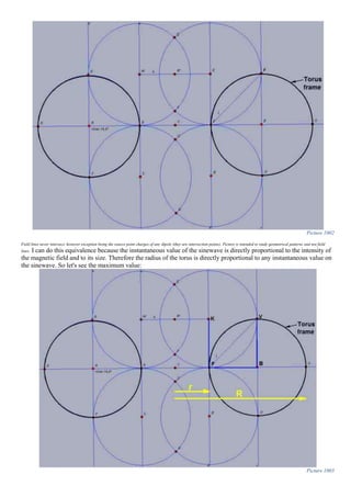
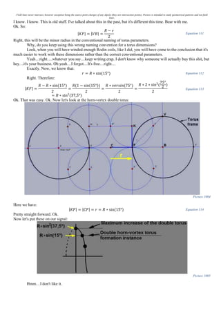
![Let me explain, and translate what we have just determined. This means that The Diameter of the whole Rodin
frame must be in a sin (15) perfect ratio with the inner diameter.
Yeah, we knew that. That's old news. This is garbage, as I said. Useless…
Not so fast. Think about this. You are wrong. It's more than meets the eye here. You don't understand. The
Radius of the whole Rodin frame must LITERALY BE a multiple of sin (15).
Hmm…
NOT JUST WITH SIN (15) GRATER THAN THE INNER SMALLER r! It must be itself a multiple of sin
(15) so that the Larger Diameter be in an even division with the inside diameter! Don't you see? This dictates that R and
r to be in an even division!!! Not just in a sin (15) ratio of sizes. And think about where we have started our analysis and
where we have reached. We wanted the maximum increase of the Rodin double torus magnetic field to be a perfect
multiple integer of the size of the double vortex and the Rodin coil responded and told us that in order for that to happen
the Diameter of the entire torus must be in an even division with the inner diameter of the hole.
<work temporary abandoned>
INDUCTANCE APPROXIMATION FOR THE RODIN COIL
Why do we need to do this?
Because in tuning LC resonance to the standing wave in the wire we must know the inductance of the Rodin
coil so that we must choose the appropriate capacitance to adjust it according to the Tesla-Smith-standing-wave
formula.
Let me make it simpler with an example:
I have a Rodin coil that has a total length of 36 meters and an inductance of 1µH.
Ok. Now Tesla-Smith formula dictates that we must use in our coil a minimum frequency of:
𝑓 =
299792458 𝑚
𝑠⁄
4 ∗ 36𝑚
= 2081892,06𝐻𝑧 ≈ 2𝑀𝐻𝑧 Equation 319
(or multiples of 2 MHz like 4 MHz, 8 MHz) to form a standing wave pattern inside the wire.
Ok. Now. If we want to set up this frequency in our Rodin coil, without forcing it and do it in a more natural way, we
must set the natural LC resonance to oscillate at 2MHz.
Ok. We know that the Rodin inductance is 1µH, then the question is what should the capacitance be?
We know that the natural LC resonance has the well-known formula:
𝑓[𝐻𝑧] =
1
2𝜋√ 𝐿[𝐻] 𝐶[𝐹]
Equation 320
So we write:
2081892,06𝐻𝑧 =
1
2𝜋√0,000001 ∗ 𝐶[𝐹]
|
2
⟺
1
4𝜋2 ∗ 1 ∗ 10−6 ∗ 𝐶[𝐹]
= 4334274549491,0436 𝐻𝑧
⟺ 4𝜋2
∗ 1 ∗ 10−6
∗ 𝐶[𝐹] =
1
4334274549491,0436 𝐻𝑧
| ∶ 4𝜋2
∗ 1 ∗ 10−6
⟹ 𝐶[𝐹] = 5,8441 ∗ 10−9
= 5,8𝑛𝐹
Equation 321
Of course this will imply that we must know the inductance of the Rodin coil…
Wait! I have an idea…What if we do this with a simple regular coil. Won’t it work? I mean, if this is what
we’re after, then why not do this with a simple regular coil?
Uff…because, if we do that, then if we tap into this LC tank circuit with a different coil that resonates on the
same frequency, we will diminish the energy in our original coil. It won’t be anything special. No magic. No overunity.
No gain. Nothing. The magnetic field will have to be on the double torus shape so that it will not be affected by our
load.
Hmm…Great. Then let’s just place two coils in opposition natural oscillating at the resonant frequency of what
Tesla-Smith formula dictates.
No. It will still not work.
Why? I mean not be affected by any load is something extraordinary!
Yes. But you won’t have overunity.
Why?](https://image.slidesharecdn.com/researchinsolidstatefreeenergygeneratorsver7-5-22-130606180846-phpapp02/85/Research-in-solid-state-free-energy-generators-ver-7-5-22-580-320.jpg)
![Because the natural LC oscillations in this two coils working in opposition, will eventually decay regardless if
you tap into this field or not. Regardless if you stress this field, by connecting through induction a collector coil, the
oscillations will still die out eventually, and you will run out of energy in the LC tank circuit. So you still don’t have
overunity.
Ok. Then let’s provide an additional input energy to this LC tank circuit!
True. But you must not connect your coil directly to an input generator, because it will disrupt the standing
wave. You want your Tesla-Smith standing wave to remain in your LC tank circuit. To be trapped there. If you connect
a wire to this oscillator, your standing wave will go also through this wire. So the only way to input additional energy
into this double torus LC tank oscillator is through induction so that your standing wave will not be disrupted or
perturbed. Then this actuator/exciter/kicker/pusher coil will have to be excited with 2 MHz (in our previous example)
with an energy higher than the total energy loss in our system, so that we can compensate it. And by all of this we have
reached at the Don Smith device. However, Smith device L2 coil is not very long, so the standing wave will form at
much higher frequencies, so the most accessible easy way to facilitate this high frequency switching at the input
actuator is by using a good-old fashion encapsulated spark-gap. It will not oscillate exactly on our frequency, because
the spark-gap has high switching noise and many harmonics. So if we set one of the lower harmonics on this frequency
that we need, then we should in theory overcome the system energy loses and attain overunity. So it’s not that simple as
you imagine. Can we get serious and get back to our Rodin inductance determination now?
Ok. We know from a conventional that a solenoid inductance can be approximated using this formula:
𝐿 =
µ0µ 𝑟 𝑁2
𝐴
𝑙
Equation 322
Where:
L=inductance of the coil expressed in mH
µ0= Permeability of free space 4*π*10-7
(adimensional)
µr=Relative permeability (adimensional).
N=number of turns in the coil (adimensional)
A=cross-sectional area of one loop in the coil expressed in mm2
l=length of the solenoid expressed in mm
Note that the Relative permeability µr sometimes noted with k is the ratio of the permeability of a specific medium to
the permeability of free space µ0:
µ 𝑟 =
µ
µ0
= 𝑘 Equation 323
Therefore our formula now becomes:
𝐿 =
µ0
µ
µ0
𝑁2
𝐴
𝑙
=
µ𝑁2
𝐴
𝑙
=
𝑘µ0 𝑁2
𝐴
𝑙
Equation 324
A more correct writing will be:
𝐿[𝑚𝐻] =
𝑘µ0 𝑁2
𝜋𝑅[𝑚𝑚]
2
𝑙[𝑚𝑚]
Equation 325
Again where:
L=inductance of the coil expressed in mH
k=relative permeability of the medium inside the coil (iron or air or whatever may be. (It can be found in tables and it's for example 1.00000037 for air and 4000 for
electrical steel)
µ0= Permeability of free space 4*π*10-7
R=radius of one circular loop in the solenoid express in mm
l=length of the solenoid expressed in mm
Now, to really understand a formula we must use imagination and picture what we are actually doing in the coil.
For start let's discard almost all the parameters in our formula and see what we are dealing here:
Let's drastically and dramatically simplify our inductance formula like this:
𝐿 = 𝑇𝑢𝑟𝑛𝑠 ∗ 𝐴𝑟𝑒𝑎 Equation 326
I already hear the police on my tail and experience readers freaking out. Ok fine! I'll change it like this:
𝐿 ≈ 𝑇𝑢𝑟𝑛𝑠 ∗ 𝐴𝑟𝑒𝑎 Equation 327
Nope. The experienced readers probably are still angry at me. Fine. Ok. Fine. Now they definitely must be at peace:
𝐿
𝑖𝑠 𝑑𝑖𝑟𝑒𝑐𝑡𝑙𝑦 𝑝𝑟𝑜𝑝𝑜𝑟𝑡𝑖𝑜𝑛𝑎𝑙 𝑡𝑜
→ 𝑇𝑢𝑟𝑛𝑠 ∗ 𝐴𝑟𝑒𝑎 Equation 328
Satisfied? Ok. Let's continue and illustrate this:](https://image.slidesharecdn.com/researchinsolidstatefreeenergygeneratorsver7-5-22-130606180846-phpapp02/85/Research-in-solid-state-free-energy-generators-ver-7-5-22-581-320.jpg)
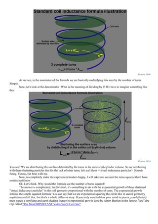
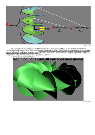
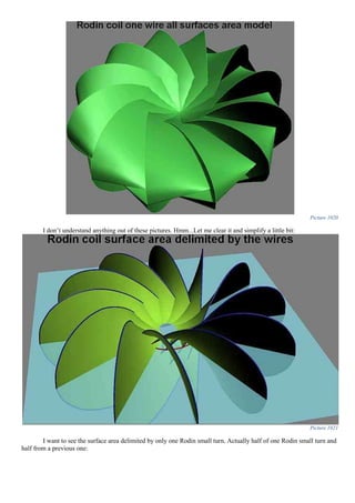

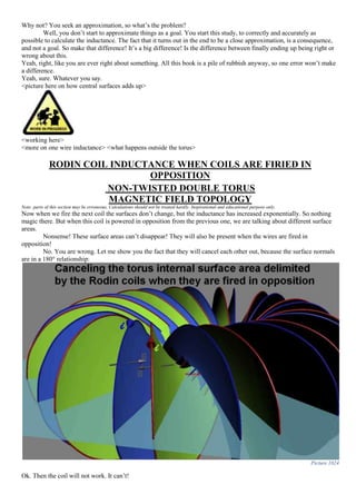
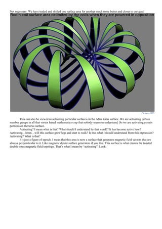
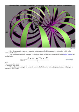
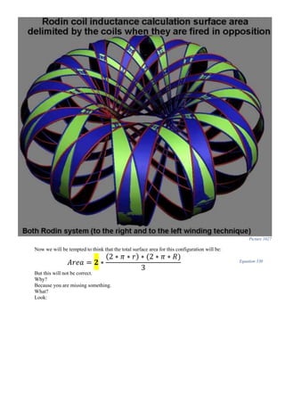
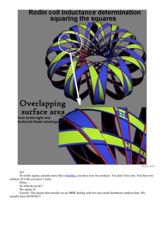
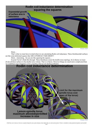
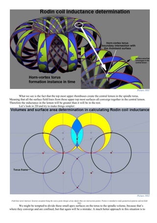
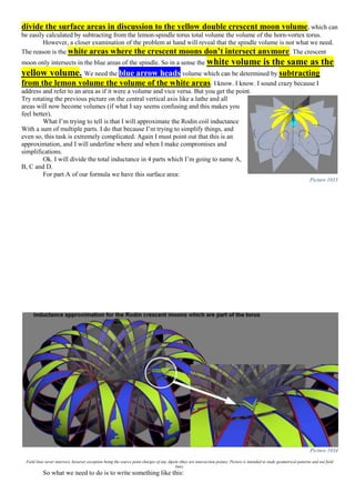
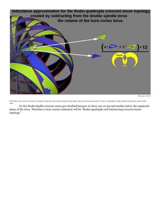
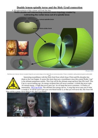
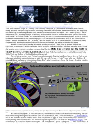
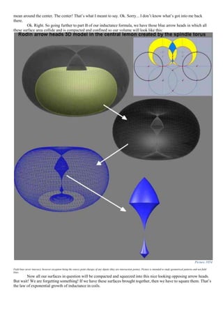
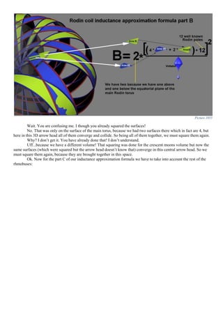
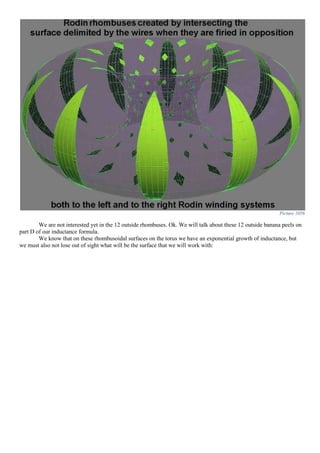

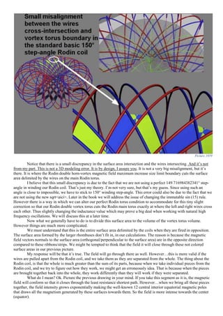
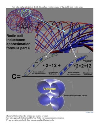
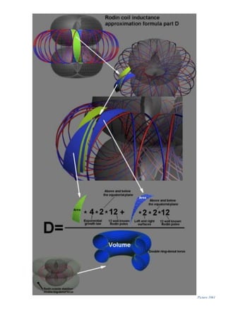
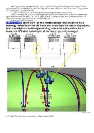
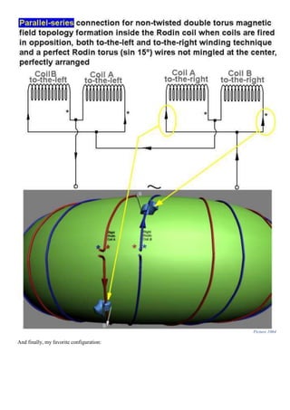
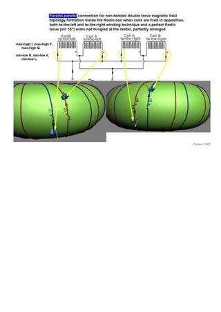
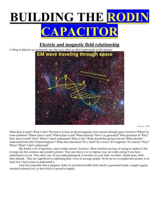
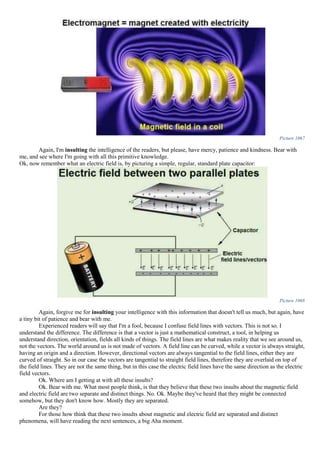
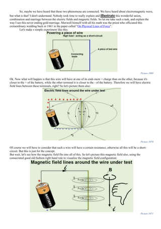
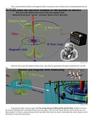
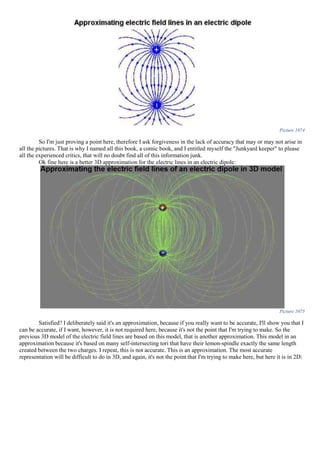
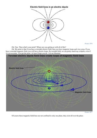
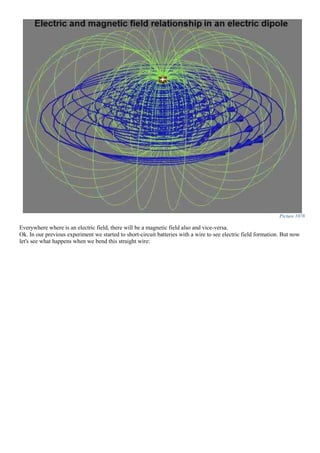

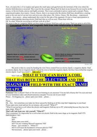
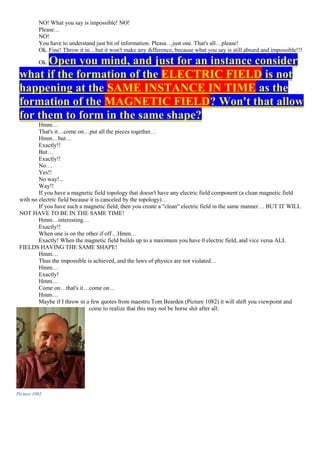
![“A succinct evaluation of that diagram and notion is given by Evans, one of the great electrodynamic theoreticians
of our times: <<I broadly agree … that the transverse plane wave view of vacuum electrodynamics is the biggest
blunder of twentieth century science. >>
Dr. Robert H. Romer, former Editor of the American Journal of Physics, also chastised the horrid
diagram shown in Figure 1-4, purporting to illustrate the transverse plane wave traveling through 3-space. In
endnote 24 of his noteworthy editorial, Dr. Romer takes that diagram to task as follows:
Picture 1083
<<...THAT DREADFUL DIAGRAMpurporting to show the electric and
magnetic fields of a plane wave, as a function of position (and/or time?) that besmirch the pages of almost every
introductory book. ...IT IS A HORRIBLE DIAGRAM!!!
MISLEADING' WOULD BE TOO KIND A WORD;
'WRONG' IS MORE ACCURATE! ...perhaps then, for historical interest,
[we should] find out how that diagram came to CONTAMINATEour literature in the first
place. >>
Picture 1084
Indeed, each point along the z-axis, is a momentary "3-space frozen slice" [...] So the entire diagram is a set of
"frozen 3-space observations", in which nothing at all is moving [...] What we are looking at in Figure 1-4 is the
iterative and very rapid results of continual "3-space observations" (frozen 3-snapshots) of an on-going 4-space
interaction.”
(Tom Bearden - Energy from the Vacuum - concepts and principles, page 52-53, paragraph 2)
"The notion of the transverse EM wave flowing through space is an artifact of the ubiquitous substitution of
the effect for the cause in Maxwellian electrodynamics. […] nonetheless, it seems we are stuck with the
ubiquitous transverse EM wave model.
So electrodynamics is still riddled with that nearly all-pervasive error, and it seems it will likely never be
corrected. The leaders of the scientific community do not seem to wish it done and will not allow it to be funded. In
short, the community is so comfortable with that grave error that it will almost defend it to the death. The so-called
transverse EM wave in 3-space has come to be accepted as if it were a law of nature.”
(Tom Bearden - Energy from the Vacuum - concepts and principles, page 207, paragraph 4)](https://image.slidesharecdn.com/researchinsolidstatefreeenergygeneratorsver7-5-22-130606180846-phpapp02/85/Research-in-solid-state-free-energy-generators-ver-7-5-22-626-320.jpg)
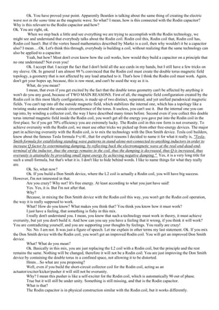
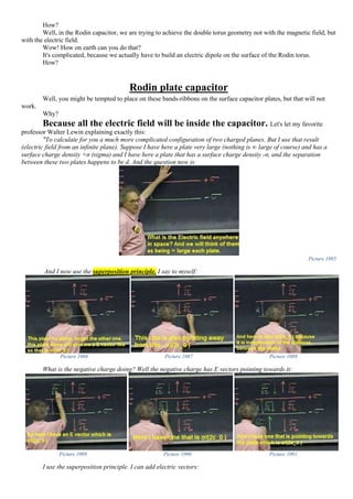
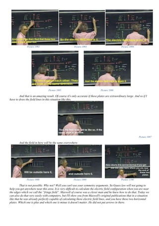
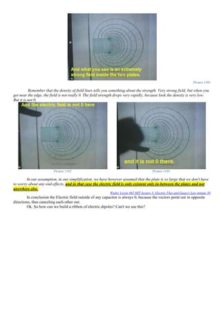
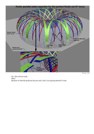
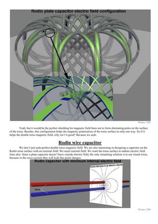
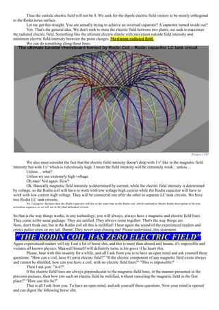
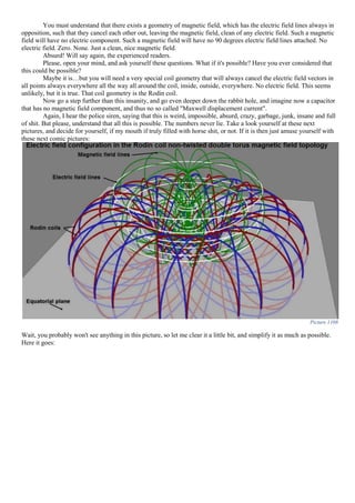
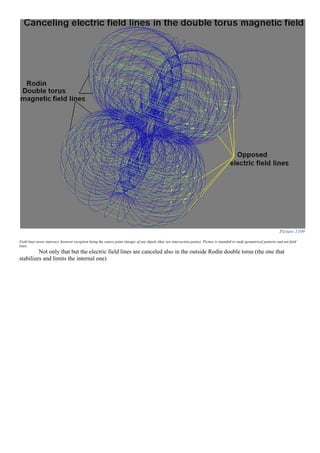

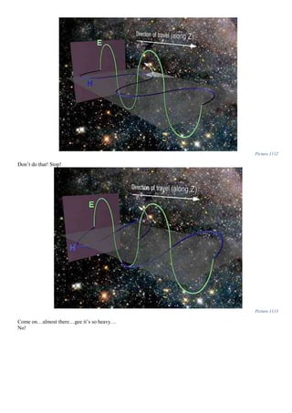

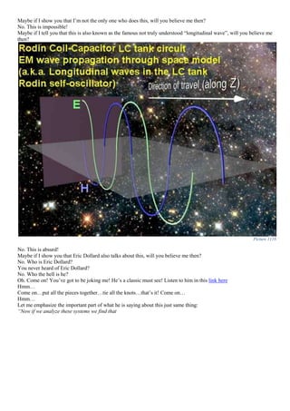
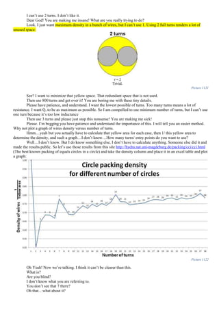
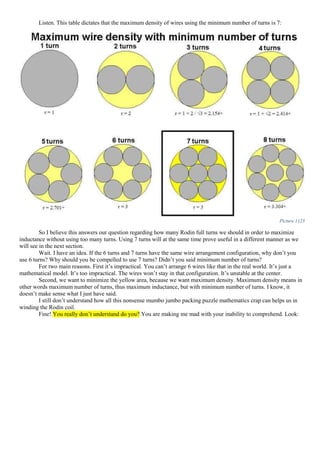
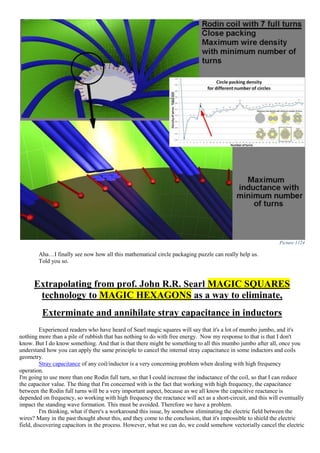


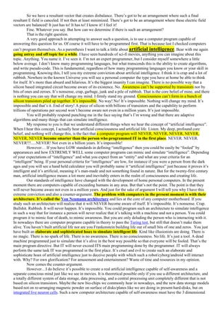

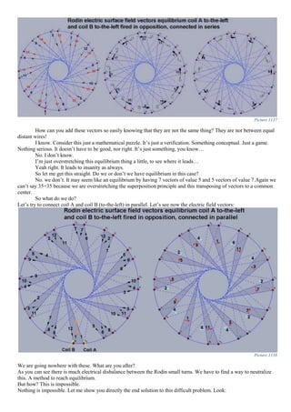
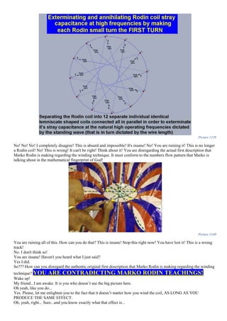
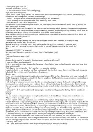
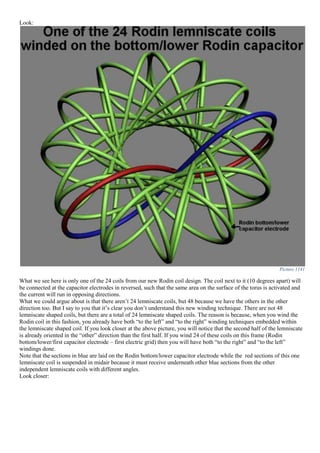
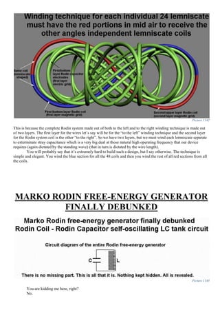
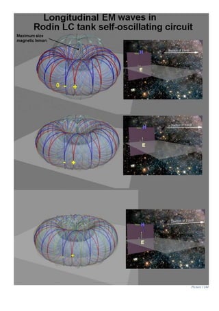
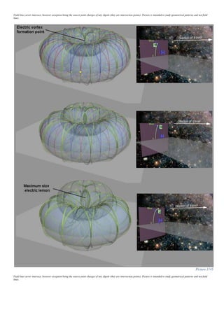
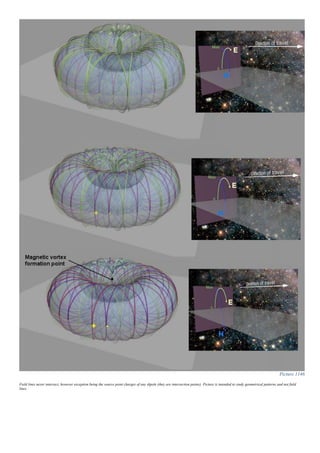
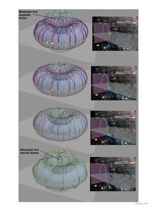
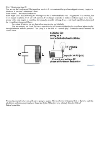
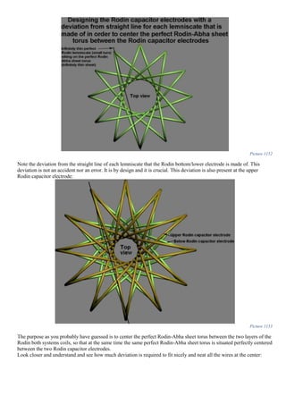
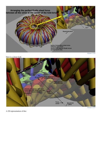
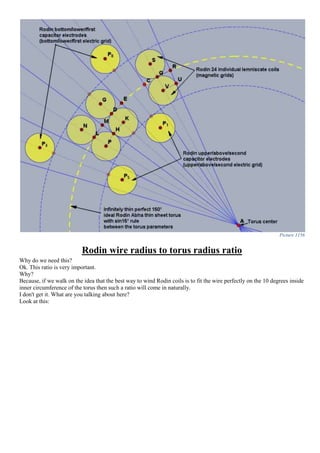
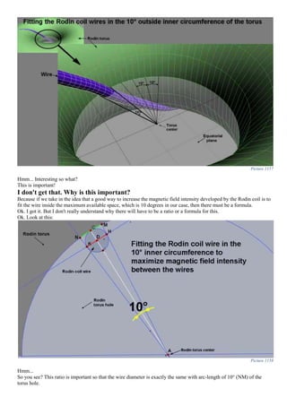
![If we know the small radius r of the inner torus hole we can determine the maximum wire size diameter (including
insulation) and vice-versa. If we know the wire diameter (including insulation) we can determine the radius of the
perfect infinitely thin sheet Abha Rodin 150° torus such that the wires fit nicely on the surface of the torus.
So what we need is to determine a relationship between segment KH and segment AC, where KH is the Rodin coil wire
diameter and segment AC is the small radius “r” of the inner hole of the torus.
|𝐾𝐻| ⊥ |𝐴𝐶| (𝑠𝑒𝑔𝑚𝑒𝑛𝑡 𝐾𝐻 𝑝𝑒𝑟𝑝𝑒𝑛𝑑𝑖𝑐𝑢𝑙𝑎𝑟 𝑡𝑜 𝑠𝑒𝑔𝑚𝑒𝑛𝑡 𝐴𝐶) Equation 332
𝑖𝑛 𝑡𝑟𝑖𝑎𝑛𝑔𝑙𝑒 ⊿𝐻𝐷𝐴 𝑤𝑒 ℎ𝑎𝑣𝑒: {
∡𝐻𝐷𝐴 = 90°
∡𝐷𝐴𝐻 = 5° 𝑏𝑒𝑐𝑎𝑢𝑠𝑒 |𝐷𝐴| 𝑖𝑠 𝑏𝑖𝑠𝑒𝑐𝑡𝑜𝑟 𝑜𝑓 𝑜𝑢𝑟 10° 𝑎𝑛𝑔𝑙𝑒
∡𝐷𝐻𝐴 = 85° 𝑏𝑒𝑐𝑎𝑢𝑠𝑒 𝑡ℎ𝑒 𝑠𝑢𝑚 𝑜𝑓 𝑎𝑙𝑙 𝑎𝑛𝑔𝑙𝑒𝑠 𝑖𝑛 𝑎 𝑡𝑟𝑖𝑎𝑛𝑔𝑙𝑒 𝑖𝑠 180°
Equation
333
𝑡ℎ𝑒𝑟𝑒𝑓𝑜𝑟𝑒 ⟶ 𝑏𝑦 𝑎𝑝𝑝𝑙𝑖𝑛𝑔 𝑎 𝑡𝑟𝑖𝑔𝑜𝑛𝑜𝑚𝑒𝑡𝑟𝑖𝑐 𝑓𝑢𝑛𝑐𝑡𝑖𝑜𝑛 𝑤𝑒 𝑐𝑎𝑛 𝑤𝑟𝑖𝑡𝑒: tan(𝐻̂) =
|𝐷𝐴|
|𝐷𝐻|
Equation
334
We can also write:
|𝐴𝐶| = |𝐷𝐴| + |𝐶𝐷| Equation 335
Let’s replace for convenience notation segment DH with small letter “i”
But segment CD is the same as segment DH, therefore:
|𝐴𝐶| = |𝐷𝐴| + 𝑖 Equation 336
By substituting further we have:
|𝐴𝐶| = 𝑖 ∗ tan(85°) + 𝑖 ⟹ Equation 337
𝒓 = 𝒊 ∗ (𝟏 + 𝐭𝐚𝐧( 𝟖𝟓°)) Equation 338
Or a more general formula:
𝒓 = 𝒊 ∗ [𝟏 + 𝐭𝐚𝐧 (𝟗𝟎° −
𝑨𝒏𝒈𝒍𝒆 𝒑𝒆𝒓 𝒔𝒆𝒄𝒕𝒐𝒓/𝒃𝒂𝒏𝒅
𝟐
)] Equation 339
Where:
r-small radius of the torus (radius of the inner hole of the torus) such that the perfect sin15 infinitely thin sheet torus lies at the center of the wires; It’s not the ideal radius, it’s the true
radius such that the ideal thin sheet torus forms in the middle of the wire. So this radius is slightly larger than ideal to accommodate for this. We are not winding the wires ON a perfect
sin15 torus, but on a different torus, such that the perfect infinitely thin sheet torus is formed in the middle of the wires.
i-radius of the Rodin coil wires;
This formula is always valid no matter the step angle. Angle per sector/band can be found in the table for all
valid Rodin step-angles configurations given previously in this book.
Where r is the small radius of the Rodin torus inner hole, and small letter “i” is the radius of the Rodin coil wires, and
there we have our much desired relationship/ratio/formula.
However, this is not so much important as we have originally thought, because the perfect-Rodin-Abha-infinitely-thin-
sheet-torus is situated elsewhere. Look:
Picture 1159
As we look at the above picture, we might say that we have achieved our goal, but that’s not quite true because we are
forgetting something. We are forgetting that we have two layers of Rodin coil wires one layer that is winded “to the
left” and the other layer above the first one that is winded “to the right”. Therefore the truth looks like this:](https://image.slidesharecdn.com/researchinsolidstatefreeenergygeneratorsver7-5-22-130606180846-phpapp02/85/Research-in-solid-state-free-energy-generators-ver-7-5-22-672-320.jpg)
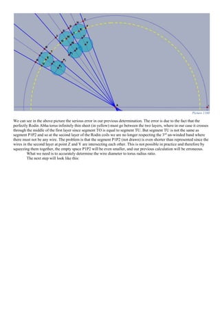
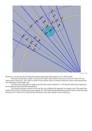
![Picture 1162
This translates in geometry terms as centering the virtual wire between the two layers (circle in red) on our long
name yellow circle.
Note that the two section marked in black in the right portion of the picture are now equal due to the average
law.
Now let’s think how we can express this mathematically:
First we acknowledge that both our wires in the first layer and second layer have the same diameter as the virtual wire
between them marked in red in the right side of our picture. Then we realize that the radius AN (segment from the
center of the torus point A to point N (outer edge of the red circle), this segment [AN] can be easily calculated from our
previously determined formula.
|𝐴𝑁| = 𝑖 ∗ (1 + tan(85°)) Equation 340
Where small letter “i” is the Rodin coil wire radius
Then we just add the segment ND to our formula and there we go:
𝑇𝑟𝑢𝑒 𝑟𝑎𝑑𝑖𝑢𝑠 𝑟 = |𝐴𝑁| + 𝑖 = 𝑖 ∗ (1 + tan(85°)) + 𝑖 Equation 341
𝑻𝒓𝒖𝒆 𝒓𝒂𝒅𝒊𝒖𝒔 𝒓 = 𝒊 ∗ ( 𝟐 + 𝐭𝐚𝐧( 𝟖𝟓°)) Equation 342
Let’s give two examplesfor all of our work:
1. Let’s assume we have a multistrand/multifilar PVC insulated copper wire with a diameter of 4,7mm. To
accurately build the perfect torus frame such that the wires correctly respect the empty space between them
(first and second layer), we will apply our formula, and have:
𝑇𝑜𝑟𝑢𝑠 𝑠𝑚𝑎𝑙𝑙 𝑟𝑎𝑑𝑖𝑢𝑠 𝑟 =
4,7
2
∗ (2 + tan(85°)) = 2,35 ∗ 13,43 = 31,56𝑚𝑚 Equation 343
And by applying the formula which is very well known by now:
𝑇𝑜𝑟𝑢𝑠 𝑙𝑎𝑟𝑔𝑒 𝑅𝑎𝑑𝑖𝑢𝑠 𝑅 =
31,56𝑚𝑚
sin(15°)
=
31,56𝑚𝑚
0,259
= 121,94𝑚𝑚 Equation 344
2. We have a torus frame with a total Diameter of D=155,3mm. We are being asked: What is the maximum
admissible wire diameter we could use such that the 3rd
un-winded empty band/space is accurately respected
between the wires at the center hole. If we use a wire to thick we will squeeze it too much at the center and we
will no longer have an empty space between the wires which must be equal to a wire diameter.
So, again, what is the maximum admissible wire diameter we are allowed to use?
To answer this question, we use the same formula:
𝑖 =
𝑟
2 + tan(85°)
Equation 345
Where i is the wire radius and r is the torus inner hole radius
We use the well rooted formula for perfect Rodin torus:](https://image.slidesharecdn.com/researchinsolidstatefreeenergygeneratorsver7-5-22-130606180846-phpapp02/85/Research-in-solid-state-free-energy-generators-ver-7-5-22-675-320.jpg)
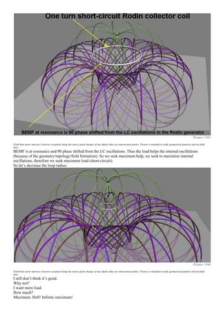
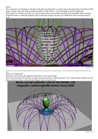
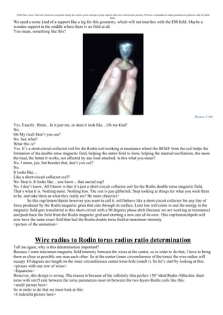
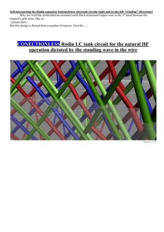

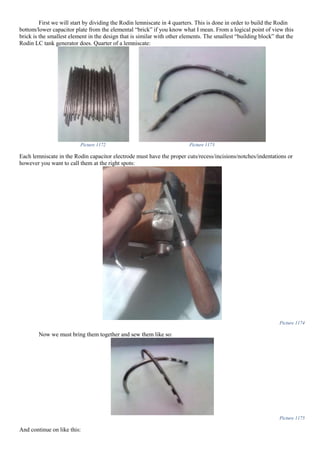
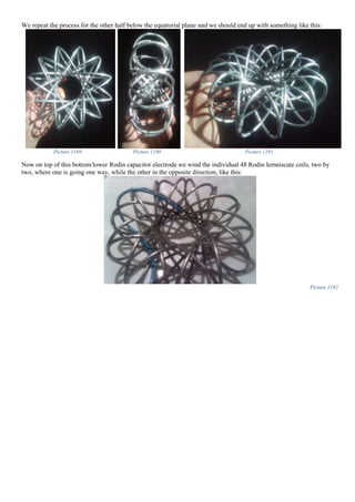
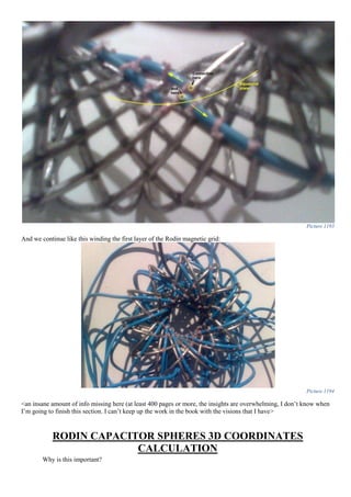
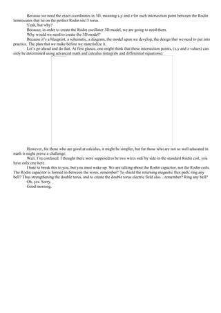
![We can say that:
|𝐶𝐵| = |𝐶𝑆| + |𝑆𝑃2| + |𝑃2 𝐵|
𝑎𝑛𝑑
|𝑆𝑃2| = |𝑃0 𝑃1|
} ⇒ |𝐶𝐵| = |𝐶𝑆| + |𝑃0 𝑃1| + |𝑃2 𝐵|
And since
|𝐶𝑆| = |𝑃2 𝐵|
|𝑃0 𝑃1| = 2 ∗ 𝑟
} ⇒ |𝐶𝐵| = 2 ∗ |𝐶𝑆| + 2 ∗ 𝑟
Where r is the small radius of the torus according to my non-conventional torus parameters definition.
Our main step-angle CAB determines the length of our lemniscate/chord CB and it’s:
𝐶𝐵 = 2 ∗ 𝑅 ∗ sin(
𝑠𝑡𝑒𝑝 𝑎𝑛𝑔𝑙𝑒
2
) = 2 ∗ 𝐶𝐴 ∗ sin(75°)
But: |𝐶𝐴| = 𝑅 where R is the big radius according to my convention. Therefore we can finally write:
2 ∗ |𝐶𝑆| + 2 ∗ 𝑟 = 2 ∗ 𝑅 ∗ sin(75°)
And, although may be irritating repeating over and over that:
𝑟 = 𝑅 ∗ sin(15°)
So we have:
2 ∗ |𝐶𝑆| + 2 ∗ 𝑅 ∗ sin(15°) = 2 ∗ 𝑅 ∗ sin(75°) | /2
We can divide all the equation by 2 and we get that:
|𝐶𝑆| = 𝑅 ∗ [sin(75°) − sin(15°)]
Since:
sin(𝐴) − sin(𝐵) = 2 cos (
𝐴 + 𝐵
2
) sin(
𝐴 − 𝐵
2
)
We can write:
|𝐶𝑆| = 𝑅 ∗ 2 ∗ cos(45°) ∗ sin(30°) ⇒
|𝐶𝑆| = 𝑅 ∗
√2
2
Now, in our right angle triangle PSC we can finally write:
in ⊿PSC: cos(𝑃𝐶𝑆̂ ) =
𝑎𝑑𝑗𝑎𝑐𝑒𝑛𝑡
ℎ𝑦𝑝𝑜𝑡𝑒𝑛𝑢𝑠𝑒
=
|𝐶𝑆|
|𝐶𝑃|
We need segment CP, so
|𝐶𝑃| =
𝑅 ∗ √2
2 ∗ cos(15°)
In the end we are after something else. This is a close up of the tiny segment we are trying to calculate:](https://image.slidesharecdn.com/researchinsolidstatefreeenergygeneratorsver7-5-22-130606180846-phpapp02/85/Research-in-solid-state-free-energy-generators-ver-7-5-22-691-320.jpg)
![This black segment can be expressed:
|𝑃𝑃7| = |𝐶𝑃7| − |𝐶𝑃| = 2 ∗ 𝑟𝑐 −
(𝑅 𝑐 + 𝑟𝑐) ∗ √2
2 ∗ cos(15°)
But we already know by now, the golden rule for building perfect 150 step angle tori, which is for conventional
parameters:
𝑟𝑐 = 𝑅 𝑐 ∗ 𝑡𝑎𝑛2
(37,5°)
And for simplicity reasons, we will make the notation:
𝑘 = 𝑡𝑎𝑛2
(37,5°)
Therefore, our segment:
|𝑃𝑃7| = 2 ∗ 𝑟𝑐 −
√2 ∗ (
𝑟𝑐
𝑘
+ 𝑟𝑐)
2 ∗ cos(15°)
= 2 ∗ 𝑟𝑐 −
(𝑟𝑐 + 𝑘 ∗ 𝑟𝑐) ∗ √2
2 ∗ 𝑘 ∗ cos(15°)
=
[2 ∗ 𝑘 ∗ cos(15°)] ∗ 2 ∗ 𝑟𝑐
[2 ∗ 𝑘 ∗ cos(15°)]
−
(𝑟𝑐 + 𝑘 ∗ 𝑟𝑐) ∗ √2
2 ∗ 𝑘 ∗ cos(15°)
=
4 ∗ 𝑘 ∗ 𝑟𝑐 ∗ cos(15°) − √2 ∗ 𝑟𝑐 ∗ (𝑘 + 1)
2 ∗ 𝑘 ∗ cos(15°)
=
√2 ∗ [2√2 ∗ 𝑘 ∗ 𝑟𝑐 ∗ cos(15°) − 𝑟𝑐 ∗ (𝑘 + 1)]
2 ∗ 𝑘 ∗ cos(15°)
=
2√2 ∗ 𝑘 ∗ 𝑟𝑐 ∗ cos(15°) − 𝑟𝑐 ∗ (𝑘 + 1)
√2 ∗ 𝑘 ∗ cos(15°)
=
𝑟𝑐 ∗ [2√2 ∗ 𝑘 ∗ cos(15°) − (𝑘 + 1)]
√2 ∗ 𝑘 ∗ cos(15°)
I detest the fact that these trigonometric values for 15° angle are hard to come about:
𝐬𝐢𝐧( 𝟏𝟓°) =
√ 𝟑−𝟏
𝟐√𝟐
and 𝐜𝐨𝐬( 𝟏𝟓°) =
√ 𝟑+𝟏
𝟐√𝟐
I hate and resent the fact that these formulas are hard to find. In God’s name, WHY? Does these angles have
leprosy or something? Why aren’t they mentioned in standard tables for trigonometric functions values? Why are they
avoided? In God’s name, WHY? I’m tormented by this question. WHY? Maybe someone out there, reading this, will
know the answer, and will be kind to enlighten me. Please.](https://image.slidesharecdn.com/researchinsolidstatefreeenergygeneratorsver7-5-22-130606180846-phpapp02/85/Research-in-solid-state-free-energy-generators-ver-7-5-22-692-320.jpg)
![Maybe because they are hard to remember, and difficult to determine see here how. Maybe if they are omitted a
quick mnemonic can be used if the table has only 0,30,45,60 and 90 degrees angles (see here). Does this answer your
question?
Returning back to our segment, we resolve the trigonometric functions and we have:
|𝑃𝑃7| =
𝑟𝑐 ∗ [𝑘 ∗ (√3 + 1) − 𝑘 − 1]
𝑘 ∗
√3 + 1
2
=
2 ∗ 𝑟𝑐 ∗ (𝑘√3 − 1)
𝑘√3 + 𝑘
You may be wondering, why on earth we are interested in this puny and tiny detail.
Exactly! I don’t understand at what good does all this calculation for a tiny and insignificant |𝑃𝑃7| segment serve?
Fine! I really have to draw everything in order for you to understand. Let’s put things into perspective and try to
understand what we have determined. Look:
What we are really after is that angle α, right there. That’s what we need.
We must immediately recognize that the segment:
|𝐴𝑃7| = 𝑟 and |𝐹𝑃7| = |𝐹𝐺| = 𝑟𝑐
So we seek to express this angle α, based on torus parameters that we know.
Therefore in our right angle triangle GPF we write:
⊿𝐺𝑃𝐹: cos(𝐺𝐹𝑃̂) =
𝑃𝐹
𝐹𝐺
However, segment |𝑃𝐹| can be written:](https://image.slidesharecdn.com/researchinsolidstatefreeenergygeneratorsver7-5-22-130606180846-phpapp02/85/Research-in-solid-state-free-energy-generators-ver-7-5-22-693-320.jpg)
![Now we can write:
|𝑃𝑋| = 2𝑅 sin(60°) = 2(𝑅 𝑐 + 𝑟𝑐) sin(60°) = 2 (
𝑟𝑐
𝑘
+ 𝑟𝑐) sin(60°) =
2𝑟𝑐(𝑘 + 1) sin(60°)
𝑘
(𝑑)
Now, we replace |𝑃𝑋| in relation (c) with the one we have in formula (d) and thus:
|𝑃𝑅| =
2𝑟𝑐(𝑘 + 1) sin(60°)
𝑘
−
2𝑟𝑐(1 − 𝑘)
𝑘
2
=
2𝑟𝑐[(𝑘 + 1) sin(60°) − (1 − 𝑘)]
2𝑘
=
𝑟𝑐[(𝑘 + 1) ∗ sin(60°) + 𝑘 − 1]
𝑘
In our right angle triangle TRP we write:
Now, let’s make another notation:
|𝑃𝑅| = 𝑟𝑐 ∗ 𝑚; where
𝑚 =
(𝑘 + 1) ∗ sin(60°) + 𝑘 − 1
𝑘
We can also say that:
|𝑇𝑃0| = 2𝑟𝑐 − 𝑟𝑐 ∗ 𝑚 = 𝑟𝑐(2 − 𝑚)
Now, we look in the following cross-section in order to determine the angle β:
We can say:
cos(𝛽) =
𝑎𝑑𝑗𝑎𝑐𝑒𝑛𝑡
ℎ𝑦𝑝𝑜𝑡𝑒𝑛𝑢𝑠𝑒
=
𝑟𝑐 − |𝑇𝑃0|
𝑟𝑐
⇒ ∡𝛽 = arccos(
𝑟𝑐 − 𝑟𝑐(2 − 𝑚)
𝑟𝑐
) = arccos(1 − (2 − 𝑚)) = arccos(m − 1)
We call the substitution, and thus:
∡𝛽 = arccos (
(𝑘 + 1) ∗ sin(60°) + 𝑘 − 1
𝑘
− 1)
Second level exact value 26,879708477101128910998146576293
Third level exact value 44,706900803632793906871630332739
Forth level exact value 72,446053801408552261202563378368
Coming soon:
Holy Eucharist and holy baptism of Rodin oscillators better identified as Rodin torsion wave generators:
Picture 1195](https://image.slidesharecdn.com/researchinsolidstatefreeenergygeneratorsver7-5-22-130606180846-phpapp02/85/Research-in-solid-state-free-energy-generators-ver-7-5-22-696-320.jpg)
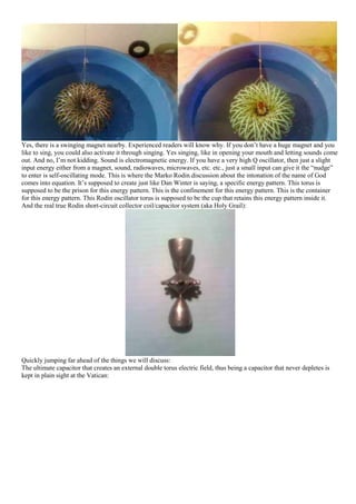
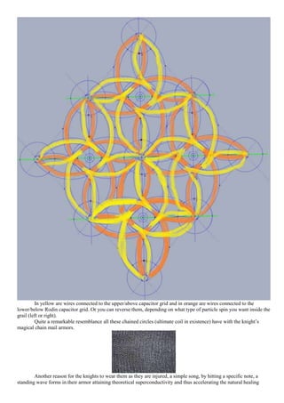
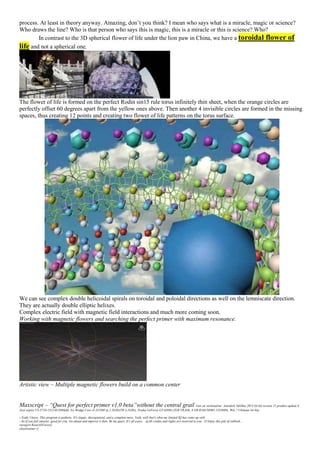
![viewport.activeviewport = 4
max tool maximize
viewport.SetRenderLevel #wireframe
max create mode
global gap_to_sphr_ratio=0.3563123713d0 --for 0.35 the ENTIRE gap is 35% of ideal SPHERE RADIUS for that level (meaning the virtual sphere with its center placed perfectly on the Abha sheet torus
global mh_to_sphr_ratio=0.8038475513d0 --magnetic hole radius is 80% of ideal sphere radius for that level
global tor_sph=17
global pol_levels=1
global pol_sph=pol_levels*2+2
global r1=62
global r2=(r1*2)/3.41421356237309504d0 as double --33,9756126404
global Max_grail_len=r2*1.84030236902122022d0 -- r2*pi*(2-sqrt(2))
global torus_r_small=r1-r2 --or global r_small=r2/sqrt(2)
global torus_R_big=r1+r2 --or global R_big=(r2*(4+sqrt(2)))/2
--declare the sphres radii and spheres gap as arrays
global sphr_out=#()
global sphr_in=#()
global sphg=#()
global ideal_r=#()
global ideal_sphr=#()
global spin_direction=0 --CW 1 is for CCW
global plength=6.28318530717958647d0*r1 --first constant is 2*pi
global pwidth=3.68060473804244045d0*r1 --and second is 2*pi*2/(2+sqrt2)
--clear everything in the scene
select $*
if ($!=undefined) do delete $
function build_ring_array lvl ang= --first argument is the level we are building and second argument is the angle for that level
(
ideal_r[lvl]=r1-r2*cos(ang)
--print ideal_r
sphg[lvl]=(gap_to_sphr_ratio*3.14159265358979323d0*(r1-r2*cos(ang)))/(3*tor_sph) as double --sphere gap for level "lvl" note that the gap is defined for the virtual sphere with its center placed ON
the ideal abha sheet torus
--print "constructing the spheres sphg[lvl] is"
-- print (sphg[lvl])
sphr_out[lvl]=(tan(60.0/tor_sph as double)*(ideal_r[lvl]-(sphg[lvl]/2 as double)*cos(ang)))/(1+tan(60.0/tor_sph as double)*cos(ang)) as double --sphere radius on the outside of the torus for level "lvl"
sphr_in[lvl]=(tan(60.0/tor_sph as double)*(ideal_r[lvl]+(sphg[lvl]/2 as double)*cos(ang)))/(1-tan(60.0/tor_sph as double)*cos(ang)) as double--sphere radius in the inside of the torus for level "lvl" (note
that this is larger than the previous one)
-- print "sphr_in[lvl]pt ring array :"
-- print (sphr_in[lvl])
real_r_out=ideal_r[lvl]-(sphr_out[lvl]+(sphg[lvl]/2 as double))*cos(ang) --actual radius of the ring array taken from the torus center to the outside sphere center of the outside ring array
real_r_in=ideal_r[lvl]+(sphr_in[lvl]+(sphg[lvl]/2 as double))*cos(ang)--actual radius of the ring array taken from the torus center to the inside sphere center of the inside ring array (note that this is
larger than the previous one)
------------------------------------------------------------------------------------create the outside level"lvl" spheres positive (above the equatorial plane) -------------------------------------------------------------------------
----
for x=1 to tor_sph do (sphere radius: sphr_out[lvl] segs:24 wirecolor: blue pos: [real_r_out*cos(360.0*x/tor_sph as double),real_r_out*sin(360.0*x/tor_sph as
double),r2*sin(ang)+(sphr_out[lvl]+sphg[lvl]/2)*sin(ang)])
--make them instances
for o in $Sphere* do o.baseobject = $Sphere001.baseobject
--rename them
for o in $Sphere* do o.name = uniquename ("Lvl" + lvl as string + "_out_pos") --Lvl2_out_pos_001
--select them
clearselection()
select (execute ("$Lvl" + lvl as string +"_out_pos*"))
--organize them in a group
group selection name: ("Lvl" + lvl as string +"_out_pos_spheres") --Lvl2_out_pos_spheres
--rotate the level if the level is an even number (this is regardless of the number of levels because i will always say level 1 is the inside equatorial spheres, thus any even number level MUST be shifted)
if ((mod lvl 2)==0) then
(
select (execute ("$Lvl" + lvl as string +"_out_pos_spheres"))
rotate selection (180.0/tor_sph as double) z_axis
)
clearselection()
------------------------------------------------------------------------------------create the outside level"lvl" spheres negative (below the equatorial plane) -------------------------------------------------------------------------
----
if (ang!=0 and ang!=180) then --on the equatorial plane there is no need to make them again
(
for x=1 to tor_sph do (sphere radius: sphr_out[lvl] segs:24 wirecolor: blue pos: [real_r_out*cos(360.0*x/tor_sph as double),real_r_out*sin(360.0*x/tor_sph as double),-
(r2*sin(ang)+(sphr_out[lvl]+sphg[lvl]/2)*sin(ang))])
--make them instances
for o in $Sphere* do o.baseobject = $Sphere001.baseobject
--rename them
for o in $Sphere* do o.name = uniquename ("Lvl" + lvl as string + "_out_neg") --Lvl2_out_neg_001
--select them
clearselection()
select (execute ("$Lvl" + lvl as string +"_out_neg*"))
--organize them in a group
group selection name: ("lvl" + lvl as string +"_out_neg_spheres") --Lvl2_out_neg_spheres
--rotate the level if the level is an even number (this is regardless of the number of levels because i will always say level 1 is the inside equatorial spheres, thus any even number level MUST
be shifted)
if ((mod lvl 2)==0) then
(
select (execute ("$Lvl" + lvl as string +"_out_neg_spheres"))
rotate selection (180.0/tor_sph as double) z_axis
)
clearselection()
)
------------------------------------------------------------------------------------create the inside level"lvl" spheres positive (above the equatorial plane) ----------------------------------------------------------------------------
-
for x=1 to tor_sph do (sphere radius: sphr_in[lvl] segs:24 wirecolor: blue pos: [real_r_in*cos(360.0*x/tor_sph as double),real_r_in*sin(360.0*x/tor_sph as double),r2*sin(ang)-
(sphr_in[lvl]+sphg[lvl]/2)*sin(ang)]) --note the different radius of the ring array and different sphere radi
--make them instances
for o in $Sphere* do o.baseobject = $Sphere001.baseobject
--rename them
for o in $Sphere* do o.name = uniquename ("Lvl" + lvl as string + "_in_pos") --Lvl2_in_pos_001
--select them
clearselection()
select (execute ("$Lvl" + lvl as string +"_in_pos*"))
--organize them in a group
group selection name: ("lvl" + lvl as string +"_in_pos_spheres") --Lvl2_in_pos_spheres
--rotate the level if the level is an even number (this is regardless of the number of levels because i will always say level 1 is the inside equatorial spheres, thus any even number level MUST be shifted)
if ((mod lvl 2)==0) then
(
select (execute ("$Lvl" + lvl as string +"_in_pos_spheres"))
rotate selection (180.0/tor_sph as double) z_axis
)
clearselection()](https://image.slidesharecdn.com/researchinsolidstatefreeenergygeneratorsver7-5-22-130606180846-phpapp02/85/Research-in-solid-state-free-energy-generators-ver-7-5-22-703-320.jpg)
![------------------------------------------------------------------------------------create the inside level"lvl" spheres negative (below the equatorial plane) ---------------------------------------------------------------------------
--
if (ang!=0 and ang!=180) then --on the equatorial plane there is no need to make them again
(
for x=1 to tor_sph do (sphere radius: sphr_in[lvl] segs:24 wirecolor: blue pos: [real_r_in*cos(360.0*x/tor_sph as double),real_r_in*sin(360.0*x/tor_sph as double),-(r2*sin(ang)-
(sphr_in[lvl]+sphg[lvl]/2)*sin(ang))]) --note the different radius of the ring array and different sphere radi
--make them instances
for o in $Sphere* do o.baseobject = $Sphere001.baseobject
--rename them
for o in $Sphere* do o.name = uniquename ("Lvl" + lvl as string + "_in_neg") --Lvl2_in_neg_001
--select them
clearselection()
select (execute ("$Lvl" + lvl as string +"_in_neg*"))
--organize them in a group
group selection name: ("lvl" + lvl as string +"_in_neg_spheres") --Lvl2_in_neg_spheres
--rotate the level if the level is an even number (this is regardless of the number of levels because i will always say level 1 is the inside equatorial spheres, thus any even number level MUST
be shifted)
if ((mod lvl 2)==0) then
(
select (execute ("$Lvl" + lvl as string +"_in_neg_spheres"))
rotate selection (180.0/tor_sph as double) z_axis
)
clearselection()
)
)
function build_magnetic_flower lvl ang_a ang_b ang_c =
(
flag=0
if (lvl<0) do
(
lvl=-lvl
flag=1
)
if (lvl==0) do
(
lvl=1
flag=1
)
if (ang_b==0 and flag==0) then flag=2
if (ang_b==180) then flag=2
"ideal r"
ideal_r[lvl]=r1-r2*cos(ang_a)
ideal_r[lvl+1]=r1-r2*cos(ang_b)
ideal_r[lvl+2]=r1-r2*cos(ang_c)
ideal_sphr[lvl+1]=ideal_r[lvl+1]*sin(60/tor_sph as double) --60 because we always have the phasing of 3
sphg[lvl]=(gap_to_sphr_ratio*3.14159265358979323d0*(r1-r2*cos(ang_a)))/(3*tor_sph) as double --sphere gap for level "lvl" note that the gap is defined for the virtual sphere with its center placed ON
the ideal abha sheet torus
sphg[lvl+1]=(gap_to_sphr_ratio*3.14159265358979323d0*(r1-r2*cos(ang_b)))/(3*tor_sph) as double
sphg[lvl+2]=(gap_to_sphr_ratio*3.14159265358979323d0*(r1-r2*cos(ang_c)))/(3*tor_sph) as double
sphr_out[lvl]=(tan(60.0/tor_sph as double)*(ideal_r[lvl]-(sphg[lvl]/2 as double)*cos(ang_a)))/(1+tan(60.0/tor_sph as double)*cos(ang_a)) as double --sphere radius on the outside of the torus for level
"lvl"
sphr_out[lvl+1]=(tan(60.0/tor_sph as double)*(ideal_r[lvl+1]-(sphg[lvl+1]/2 as double)*cos(ang_b)))/(1+tan(60.0/tor_sph as double)*cos(ang_b)) as double
sphr_out[lvl+2]=(tan(60.0/tor_sph as double)*(ideal_r[lvl+2]-(sphg[lvl+2]/2 as double)*cos(ang_c)))/(1+tan(60.0/tor_sph as double)*cos(ang_c)) as double
sphr_in[lvl]=(tan(60.0/tor_sph as double)*(ideal_r[lvl]+(sphg[lvl]/2 as double)*cos(ang_a)))/(1-tan(60.0/tor_sph as double)*cos(ang_a)) as double--sphere radius in the inside of the torus for level "lvl"
(note that this is larger than the previous one)
sphr_in[lvl+1]=(tan(60.0/tor_sph as double)*(ideal_r[lvl+1]+(sphg[lvl+1]/2 as double)*cos(ang_b)))/(1-tan(60.0/tor_sph as double)*cos(ang_b)) as double
sphr_in[lvl+2]=(tan(60.0/tor_sph as double)*(ideal_r[lvl+2]+(sphg[lvl+2]/2 as double)*cos(ang_c)))/(1-tan(60.0/tor_sph as double)*cos(ang_c)) as double
mh=ideal_sphr[lvl+1]*mh_to_sphr_ratio
fg2=sphr_out[lvl+1]+sphg[lvl+1]+sphr_in[lvl+1]
fg3=sphr_out[lvl+2]+sphg[lvl+2]+sphr_in[lvl+2]
true_angle=2*asin(sin(180/tor_sph as double)*cos(ang_b)) --the true orbital angle of the spheres (pointing up at a polar point on the world axis) this determines a new angle different from standard 180/tor_sph, but
based on it
--new_z=(fg3/2)-sphr_out[lvl+2]-(sphg[lvl+2]/2 as double)
tor_petal=(ideal_r[lvl+1]*3.14159265358979323d0)/tor_sph as double
--maybe someone real smart could develop a for loop for the following 16 segments, i could do it in a couple of hours, but i don't see if there will be a real speed improvement upon the code execution, only
a structural improvement
--quadrant 1
if (ang_b==180) then xypos1=(ang_b-ang_a)*r2*0.01234134149488435d0 --this is is because at the outside ecuator the magnetic flower turns itself over
else xypos1=(ang_c-ang_b)*r2*0.01234134149488435d0 --constant comes from pi/(sqrt(2)*180) --xy position in the first quadrant
xypos1=abs(xypos1)
spl = convertToSplineShape(Ellipse adaptive: true ellipse_outline:off length:(2*xypos1) width:(2*(xypos1+mh)) ellipse_thickness:0 pos:[xypos1,0,0] )
open spl 1
deleteKnot spl 1 4
deleteKnot spl 1 1
crd1=(getKnotPoint spl 1 1)
if (spin_direction==0) then (crd1[3]+=-(sphr_in[lvl+2]+(sphg[lvl+2]/2 as double))) else (crd1[3]+=(sphr_out[lvl+2]+(sphg[lvl+2]/2 as double)))
setKnotPoint spl 1 1 crd1
updateshape spl --if i don't put this here the tangents don't get reset with the new repositioning!!!
--measure it to see if it's within boundary
tmp=snapshot $Ellipse001
rotate tmp -45 z_axis
resetxform tmp
maxOps.CollapseNode tmp false
dif=tmp.max.y-tmp.min.y
delete tmp
spl = convertToSplineShape(Ellipse adaptive: true ellipse_outline:off length:(2*xypos1) width:(2*(xypos1-mh)) ellipse_thickness:0 pos:[xypos1,0,0])
open spl 1
deleteKnot spl 1 4
deleteKnot spl 1 1
crd2=(getKnotPoint spl 1 1)
if (spin_direction==0) then (crd2[3]+=(sphr_out[lvl+2]+(sphg[lvl+2]/2 as double))) else (crd2[3]+=-(sphr_in[lvl+2]+(sphg[lvl+2]/2 as double)))
setKnotPoint spl 1 1 crd2
updateshape spl --if i don't put this here the tangents don't get reset with the new repositioning!!!
spl = convertToSplineShape(Ellipse adaptive: true ellipse_outline:off length:(2*(xypos1-mh)) width:(2*xypos1) ellipse_thickness:0 pos:[0,xypos1,0])
setFirstKnot spl 1 2
open spl 1
deleteKnot spl 1 2
deleteKnot spl 1 1
setKnotPoint spl 1 2 crd1
updateshape spl --if i don't put this here the tangents don't get reset with the new repositioning!!!
spl = convertToSplineShape(Ellipse adaptive: true ellipse_outline:off length:(2*(xypos1+mh)) width:(2*xypos1) ellipse_thickness:0 pos:[0,xypos1,0])
setFirstKnot spl 1 2
open spl 1
deleteKnot spl 1 2
deleteKnot spl 1 1
setKnotPoint spl 1 2 crd2](https://image.slidesharecdn.com/researchinsolidstatefreeenergygeneratorsver7-5-22-130606180846-phpapp02/85/Research-in-solid-state-free-energy-generators-ver-7-5-22-704-320.jpg)
![updateshape spl --if i don't put this here the tangents don't get reset with the new repositioning!!!
/*
--scaling error when the third level angle is too high that the ellipse steps out of bounds
if (dif>tor_petal) do
(--we must scale it down
--first let's group it
group $Ellipse* name: "tmp"
rotate $tmp -45 z_axis
scale $tmp [1,(tor_petal/dif as double),1]
rotate $tmp 45 z_axis
ungroup $tmp
for o in $Ellipse* do
(
resetxform o
maxOps.CollapseNode o false
)
--reposition the magnetic hole points
setKnotPoint $Ellipse001 1 2 [-mh,0,0]
setKnotPoint $Ellipse002 1 2 [mh,0,0]
setKnotPoint $Ellipse003 1 1 [0,mh,0]
setKnotPoint $Ellipse004 1 1 [0,-mh,0]
)
*/
--quadrant 4
xypos4=tor_petal/1.41421356237309504d0 as double --reduced by sqrt(2)
spl = convertToSplineShape(Ellipse adaptive: true ellipse_outline:off length:(2*(xypos4+mh)) width:(2*xypos4) ellipse_thickness:0 pos:[0,-xypos4,0])
open spl 1
deleteKnot spl 1 4
deleteKnot spl 1 3
crd1=(getKnotPoint spl 1 1)
if (spin_direction==0) then (crd1[3]+=-(sphr_in[lvl+1]+(sphg[lvl+1]/2 as double))) else (crd1[3]+=(sphr_out[lvl+1]+(sphg[lvl+1]/2 as double)))
setKnotPoint spl 1 1 crd1
updateshape spl
spl = convertToSplineShape(Ellipse adaptive: true ellipse_outline:off length:(2*(xypos4-mh)) width:(2*xypos4) ellipse_thickness:0 pos:[0,-xypos4,0])
open spl 1
deleteKnot spl 1 4
deleteKnot spl 1 3
crd2=(getKnotPoint spl 1 1)
if (spin_direction==0) then (crd2[3]+=(sphr_out[lvl+1]+(sphg[lvl+1]/2 as double))) else (crd2[3]+=-(sphr_in[lvl+1]+(sphg[lvl+1]/2 as double)))
setKnotPoint spl 1 1 crd2
updateshape spl
spl = convertToSplineShape(Ellipse adaptive: true ellipse_outline:off length:(2*xypos4) width:(2*(xypos4-mh)) ellipse_thickness:0 pos:[xypos4,0,0])
open spl 1
deleteKnot spl 1 2
deleteKnot spl 1 1
setKnotPoint spl 1 2 crd1
updateshape spl
spl = convertToSplineShape(Ellipse adaptive: true ellipse_outline:off length:(2*xypos4) width:(2*(xypos4+mh)) ellipse_thickness:0 pos:[xypos4,0,0])
open spl 1
deleteKnot spl 1 2
deleteKnot spl 1 1
setKnotPoint spl 1 2 crd2
updateshape spl
--quadrant 3
xypos3=(ang_b-ang_a)*r2*0.01234134149488435d0 --constant comes from pi/(sqrt(2)*180)
spl = convertToSplineShape(Ellipse adaptive: true ellipse_outline:off length:(2*xypos3) width:(2*(xypos3+mh)) ellipse_thickness:0 pos:[-xypos3,0,0])
setFirstKnot spl 1 2
open spl 1
deleteKnot spl 1 2
deleteKnot spl 1 1
crd1=(getKnotPoint spl 1 1)
if (spin_direction==0) then (crd1[3]+=-(sphr_in[lvl]+(sphg[lvl]/2 as double))) else (crd1[3]+=(sphr_out[lvl]+(sphg[lvl]/2 as double)))
setKnotPoint spl 1 1 crd1
updateshape spl
spl = convertToSplineShape(Ellipse adaptive: true ellipse_outline:off length:(2*xypos3) width:(2*(xypos3-mh)) ellipse_thickness:0 pos:[-xypos3,0,0])
setFirstKnot spl 1 2
open spl 1
deleteKnot spl 1 2
deleteKnot spl 1 1
crd2=(getKnotPoint spl 1 1)
if (spin_direction==0) then (crd2[3]+=(sphr_out[lvl]+(sphg[lvl]/2 as double))) else (crd2[3]+=-(sphr_in[lvl]+(sphg[lvl]/2 as double)))
setKnotPoint spl 1 1 crd2
updateshape spl
spl = convertToSplineShape(Ellipse adaptive: true ellipse_outline:off length:(2*(xypos3-mh)) width:(2*xypos3) ellipse_thickness:0 pos:[0,-xypos3,0])
open spl 1
deleteKnot spl 1 4
deleteKnot spl 1 1
setKnotPoint spl 1 2 crd1
updateshape spl
spl = convertToSplineShape(Ellipse adaptive: true ellipse_outline:off length:(2*(xypos3+mh)) width:(2*xypos3) ellipse_thickness:0 pos:[0,-xypos3,0])
open spl 1
deleteKnot spl 1 4
deleteKnot spl 1 1
setKnotPoint spl 1 2 crd2
updateshape spl
--quadrant 2
(copy $Ellipse005).pos.y=-$Ellipse005.pos.y
rotate $Ellipse013 180 z_axis
(copy $Ellipse006).pos.y=-$Ellipse006.pos.y
rotate $Ellipse014 180 z_axis
(copy $Ellipse007).pos.x=-$Ellipse007.pos.x
rotate $Ellipse015 180 z_axis
(copy $Ellipse008).pos.x=-$Ellipse008.pos.x
rotate $Ellipse016 180 z_axis
--combine everything in one flower
select $Ellipse001
--$.name="Ellipse000"
if (flag==1) then $.name = "lvl0_mag_flower"
else $.name = ("lvl" + lvl as string + "_mag_flower")
for o in $Ellipse* do (addAndWeld $ o -1)
$.pivot = [0,0,0]](https://image.slidesharecdn.com/researchinsolidstatefreeenergygeneratorsver7-5-22-130606180846-phpapp02/85/Research-in-solid-state-free-energy-generators-ver-7-5-22-705-320.jpg)
![--$.pivot = [-xypos3,-xypos3,-new_z] --MAX YOUR ATTENTION HERE! REPOSITIONING THE PIVOT POINT ON THE THIRD COORDINATE OZ IS IMPORTANT
--THE BEND IS APPLIED ACORDING TO THE PIVOT POINT OF THE ENTIRE BOUNDING BOX. THIS MUST BE CENTERED ACORDING TO THE LONGEST DISTANCE, WHICH IS
FG3(FLOWER GAP LEVEL 3)
$.wirecolor = yellow
--$.pivot = [0,0,0]
rotate $ -45 z_axis
--rotate $ -90 y_axis
resetxform $
--close $ 1
maxOps.CollapseNode $ false
--rotate $ (ang_a) y_axis
my_scale=(plength/(6.28318530717958647d0*ideal_r[lvl+1]) as double)
--position it on poloidal direction ox corectly
shift=0
if ((mod lvl 2)==1 and flag!=1) then shift=1
posx=-(pwidth/2 as double)+(ang_b*r2*0.01745329251994329d0)
posy=-(plength/2 as double)+(ideal_r[lvl+1]*3.14159265358979323d0/tor_sph as double)*(shift)*(my_scale)
$.pos=[posx,posy,0]
for i=1 to (tor_sph-1) do
(
(copy $).pos.y=-(plength/2 as double)+(ideal_r[lvl+1]*3.14159265358979323d0/tor_sph as double)*(shift)*(my_scale)+i*((ideal_r[lvl+1]*6.28318530717958647d0)/tor_sph as double)
)
--join all magnetic flowers in a row
if (flag==1) then
(
g=$lvl0_mag_flower
all=execute ("$Lvl0_mag_flower0*")
)
else (g=execute ("$lvl" + lvl as string+ "_mag_flower")
all=execute ("$Lvl" + lvl as string+ "_mag_flower0*")
)
select g
a= for o in all where (o!=g) collect o
for o in a do (addAndWeld $ o -1)
scale $ [1,my_scale,1]
$.wirecolor = yellow
if (ang_b!=0 and ang_b!=180) do
(
g=copy $
rotate g 180 y_axis
rotate g 180 x_axis
g.pos.x = (pwidth/2 as double)-(ang_b*r2*0.01745329251994329d0)
g.pos.y=-g.pos.y
)
)
--$Ellipse001.modifiers[#Taper].primaryaxis = 0
--$Ellipse001.modifiers[#Taper].effectaxis = 1
--$Ellipse001.modifiers[#Taper].amount = -0.1ree
--plane length: plength width: pwidth lengthsegs: 48 widthsegs: 24 wirecolor: [86,86,86] pos: [0,0,0] name: "Main torus plane" isSelected: true
--rotate $ 90 y_axis
--actionMan.executeAction 0 "40077" -- Views: Hide Grids Toggle
build_magnetic_flower -1 -6.29341260317974431d0 0 6.29341260317974431d0
build_magnetic_flower 1 0 6.29341260317974431d0 12.74456697675817935d0
build_magnetic_flower 2 6.29341260317974431d0 12.74456697675817935d0 19.53154156505148393d0
build_magnetic_flower 3 12.74456697675817935d0 19.53154156505148393d0 26.87970847710112891d0
build_magnetic_flower 4 19.53154156505148393d0 26.87970847710112891d0 35.10624783548284463d0
build_magnetic_flower 5 26.87970847710112891d0 35.10624783548284463d0 44.70690080363279390d0
build_magnetic_flower 6 35.10624783548284463d0 44.70690080363279390d0 56.55372154508091360d0
build_magnetic_flower 7 44.70690080363279390d0 56.55372154508091360d0 72.44605380140855226d0
build_magnetic_flower 8 56.55372154508091360d0 72.44605380140855226d0 97.27323810765686261d0
build_magnetic_flower 9 72.44605380140855226d0 97.27323810765686261d0 180
build_magnetic_flower 10 97.27323810765686261d0 180 -97.27323810765686261d0
g= $lvl0_mag_flower
select g
a= for o in $lvl* where (o!=g) collect o
for o in a do (addAndWeld g o -1)
g.pivot=[0,0,0]
resetxform g
maxOps.CollapseNode g false
addmodifier g (Bend bendaxis: 0)
g.modifiers[#Bend].gizmo.pos = [0,0,0]
pmin=getModContextBBoxMin $ $.bend
pmax=getModContextBBoxMax $ $.bend
pmin[1]=-pmax[1]
pmin[2]=-Plength/2
pmax[2]=-pmin[2]
setModContextBBox $ $.bend pmin pmax
g.bend.bendangle = 360
$.pivot=[0,0,-r2]
dif=abs($.pivot.z-$.center.z)
$.center=[0,0,dif]
resetxform $
maxOps.CollapseNode $ false
clearselection()
g=$lvl0_mag_flower
select g
addmodifier $ (Bend bendaxis: 1)
$.modifiers[#bend].gizmo.rotation += quat 0 0.707107 0 0.707107
pmin=getModContextBBoxMin g g.bend
pmax=getModContextBBoxMax g g.bend
pmin[2]=-Plength/2
pmax[2]=-pmin[2]
pmin[1]=-pmax[3]
pmax[1]=pmax[3]
pmin[3]=-pmax[3]
setModContextBBox g g.bend pmin pmax
g.bend.bendangle = 360
$.pivot=$.center
$.center=[0,0,0]
rotate $ 90 y_axis
resetxform $
maxOps.CollapseNode $ false](https://image.slidesharecdn.com/researchinsolidstatefreeenergygeneratorsver7-5-22-130606180846-phpapp02/85/Research-in-solid-state-free-energy-generators-ver-7-5-22-706-320.jpg)
![--rotate $ (180/tor_sph as double) z_axis
-- BUILDING THE PRIMER
--BUILD THE MAIN TORUS OF THE PRIMER
torus radius1: r1 radius2: r2 segments: 200 sides: 200 name: "_Main torus" smooth: 2 wirecolor: [86,86,86] pos: [0,0,0] --48 cu 24 segmente
--build level 1 spheres (at the equatorial plane) with angle 0 degrees
build_ring_array 1 0
build_ring_array 2 6.29341260317974431d0
build_ring_array 3 12.74456697675817935d0
build_ring_array 4 19.53154156505148393d0
build_ring_array 5 26.87970847710112891d0
build_ring_array 6 35.10624783548284463d0
build_ring_array 7 44.70690080363279390d0
build_ring_array 8 56.55372154508091360d0
build_ring_array 9 72.44605380140855226d0
build_ring_array 10 97.27323810765686261d0
build_ring_array 11 180
/*
--construct magnetic flowers using 1 turn helix for each level
--2 levels
for a[1]=0.0 to 180.0 step 0.1 do
(
b[1] =pol_helix_len (0,a[1],mh,sphg)
if (2*b[1]<=Max_grail_len) then
(
for a[2]=a[1] to 180 step 0.1 do
(
b[2]=pol_helix_len(a[1],a[2],mh,sphg)
if ((b[1]+b[2])<=Max_grail_len) then
(
b[3]=pol_helix_len(a[2],180,mh,sphg)
if ((b[3]+b[2])<=Max_grail_len) then
(
s=0
for i=1 to 3 do s+=b[i]*2
for i=1 to 3 do rez[i]=(mod(b[i]/s,2)/2)*100 --calculate each helix resonance factor
rez_sum=0 --make the average of all resonance factors
for i=1 to 3 do rez_sum+=rez[i]
rez_avg=rez_sum/3
print "level 2, 6 spheres" a[1] a[2] rez_avg
)
)
else break
)
)
else break
)
Note that the code above, doesn’t even touch the Holy Chalice that must be place at the center. There will be an insane
amount of work needed to be done there as well. It’s all decorated all over the place with hemispheres, carefully
calculated and positioned on the cup surface. I don’t even know where to start and show you what I see in my mind’s
eye about this cup. I have seen the interaction with the primer, and it’s the most amazing thing there is in existence and
that I have ever imagined. The complexity of interacting EM fields between the grail and the primer is overwhelming.
May God give me strength to show to others what I’ve seen.
End result:
The Tree of life (and the one in the movie “The Fountain”)
I don’t have to mention the simple activation sequence of the prototype by a simple submerging and then raising above
water (baptism). So it only works above water, because water acts like a variable dielectric for the Rodin capacitor
spheres, thus fine-tuning the LC resonance point to the standing wave dictated by the magnetic flowers.
Magic carpet before converting it to a torus:](https://image.slidesharecdn.com/researchinsolidstatefreeenergygeneratorsver7-5-22-130606180846-phpapp02/85/Research-in-solid-state-free-energy-generators-ver-7-5-22-707-320.jpg)