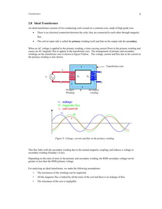
Transformers operate by exploiting the principle of mutual inductance between two coils. They are used to convert alternating current (AC) voltages from one level to another. An ideal transformer consists of two coils wound on a common magnetic core, with no direct electrical connection between them. Current flowing through the primary coil produces a changing magnetic flux that induces a voltage in the secondary coil. Transformers are widely used in power distribution systems to increase or decrease voltages as needed.
This Presentation gives a basic idea about Electromagnetic induction,Faraday's Law ,Lenz's law and the application of Electromagnetic Induction. I included some real life examples of electromagnetic induction also. I hope everyone will like it
Magnetic Circuits, Self and Mutual
inductances, dot convention, impedance, reactance concept, Impedance transformation and
coupled circuits, co-efficient of coupling, equivalent T for Magnetically coupled circuits,
Ideal Transformer.
In statically induced emf, conductor is stationary with respect to the magnetic field.
Transformer is an example of statically induced emf. Here the windings are stationary,magnetic field is moving around the conductor and produces the emf.
this is my investigatory file I made for class XII on the topic electromagnetic induction (EMI).there 2 document with same name 1 is in pdf and another one is in docx.
Student information management system project report ii.pdfKamal Acharya
Our project explains about the student management. This project mainly explains the various actions related to student details. This project shows some ease in adding, editing and deleting the student details. It also provides a less time consuming process for viewing, adding, editing and deleting the marks of the students.
Water scarcity is the lack of fresh water resources to meet the standard water demand. There are two type of water scarcity. One is physical. The other is economic water scarcity.
CFD Simulation of By-pass Flow in a HRSG module by R&R Consult.pptxR&R Consult
CFD analysis is incredibly effective at solving mysteries and improving the performance of complex systems!
Here's a great example: At a large natural gas-fired power plant, where they use waste heat to generate steam and energy, they were puzzled that their boiler wasn't producing as much steam as expected.
R&R and Tetra Engineering Group Inc. were asked to solve the issue with reduced steam production.
An inspection had shown that a significant amount of hot flue gas was bypassing the boiler tubes, where the heat was supposed to be transferred.
R&R Consult conducted a CFD analysis, which revealed that 6.3% of the flue gas was bypassing the boiler tubes without transferring heat. The analysis also showed that the flue gas was instead being directed along the sides of the boiler and between the modules that were supposed to capture the heat. This was the cause of the reduced performance.
Based on our results, Tetra Engineering installed covering plates to reduce the bypass flow. This improved the boiler's performance and increased electricity production.
It is always satisfying when we can help solve complex challenges like this. Do your systems also need a check-up or optimization? Give us a call!
Work done in cooperation with James Malloy and David Moelling from Tetra Engineering.
More examples of our work https://www.r-r-consult.dk/en/cases-en/
Forklift Classes Overview by Intella PartsIntella Parts
Discover the different forklift classes and their specific applications. Learn how to choose the right forklift for your needs to ensure safety, efficiency, and compliance in your operations.
For more technical information, visit our website https://intellaparts.com
Sachpazis:Terzaghi Bearing Capacity Estimation in simple terms with Calculati...Dr.Costas Sachpazis
Terzaghi's soil bearing capacity theory, developed by Karl Terzaghi, is a fundamental principle in geotechnical engineering used to determine the bearing capacity of shallow foundations. This theory provides a method to calculate the ultimate bearing capacity of soil, which is the maximum load per unit area that the soil can support without undergoing shear failure. The Calculation HTML Code included.
Welcome to WIPAC Monthly the magazine brought to you by the LinkedIn Group Water Industry Process Automation & Control.
In this month's edition, along with this month's industry news to celebrate the 13 years since the group was created we have articles including
A case study of the used of Advanced Process Control at the Wastewater Treatment works at Lleida in Spain
A look back on an article on smart wastewater networks in order to see how the industry has measured up in the interim around the adoption of Digital Transformation in the Water Industry.
Automobile Management System Project Report.pdfKamal Acharya
The proposed project is developed to manage the automobile in the automobile dealer company. The main module in this project is login, automobile management, customer management, sales, complaints and reports. The first module is the login. The automobile showroom owner should login to the project for usage. The username and password are verified and if it is correct, next form opens. If the username and password are not correct, it shows the error message.
When a customer search for a automobile, if the automobile is available, they will be taken to a page that shows the details of the automobile including automobile name, automobile ID, quantity, price etc. “Automobile Management System” is useful for maintaining automobiles, customers effectively and hence helps for establishing good relation between customer and automobile organization. It contains various customized modules for effectively maintaining automobiles and stock information accurately and safely.
When the automobile is sold to the customer, stock will be reduced automatically. When a new purchase is made, stock will be increased automatically. While selecting automobiles for sale, the proposed software will automatically check for total number of available stock of that particular item, if the total stock of that particular item is less than 5, software will notify the user to purchase the particular item.
Also when the user tries to sale items which are not in stock, the system will prompt the user that the stock is not enough. Customers of this system can search for a automobile; can purchase a automobile easily by selecting fast. On the other hand the stock of automobiles can be maintained perfectly by the automobile shop manager overcoming the drawbacks of existing system.
Hybrid optimization of pumped hydro system and solar- Engr. Abdul-Azeez.pdffxintegritypublishin
Advancements in technology unveil a myriad of electrical and electronic breakthroughs geared towards efficiently harnessing limited resources to meet human energy demands. The optimization of hybrid solar PV panels and pumped hydro energy supply systems plays a pivotal role in utilizing natural resources effectively. This initiative not only benefits humanity but also fosters environmental sustainability. The study investigated the design optimization of these hybrid systems, focusing on understanding solar radiation patterns, identifying geographical influences on solar radiation, formulating a mathematical model for system optimization, and determining the optimal configuration of PV panels and pumped hydro storage. Through a comparative analysis approach and eight weeks of data collection, the study addressed key research questions related to solar radiation patterns and optimal system design. The findings highlighted regions with heightened solar radiation levels, showcasing substantial potential for power generation and emphasizing the system's efficiency. Optimizing system design significantly boosted power generation, promoted renewable energy utilization, and enhanced energy storage capacity. The study underscored the benefits of optimizing hybrid solar PV panels and pumped hydro energy supply systems for sustainable energy usage. Optimizing the design of solar PV panels and pumped hydro energy supply systems as examined across diverse climatic conditions in a developing country, not only enhances power generation but also improves the integration of renewable energy sources and boosts energy storage capacities, particularly beneficial for less economically prosperous regions. Additionally, the study provides valuable insights for advancing energy research in economically viable areas. Recommendations included conducting site-specific assessments, utilizing advanced modeling tools, implementing regular maintenance protocols, and enhancing communication among system components.
Overview of the fundamental roles in Hydropower generation and the components involved in wider Electrical Engineering.
This paper presents the design and construction of hydroelectric dams from the hydrologist’s survey of the valley before construction, all aspects and involved disciplines, fluid dynamics, structural engineering, generation and mains frequency regulation to the very transmission of power through the network in the United Kingdom.
Author: Robbie Edward Sayers
Collaborators and co editors: Charlie Sims and Connor Healey.
(C) 2024 Robbie E. Sayers
Quality defects in TMT Bars, Possible causes and Potential Solutions.PrashantGoswami42
Maintaining high-quality standards in the production of TMT bars is crucial for ensuring structural integrity in construction. Addressing common defects through careful monitoring, standardized processes, and advanced technology can significantly improve the quality of TMT bars. Continuous training and adherence to quality control measures will also play a pivotal role in minimizing these defects.
Immunizing Image Classifiers Against Localized Adversary Attacksgerogepatton
This paper addresses the vulnerability of deep learning models, particularly convolutional neural networks
(CNN)s, to adversarial attacks and presents a proactive training technique designed to counter them. We
introduce a novel volumization algorithm, which transforms 2D images into 3D volumetric representations.
When combined with 3D convolution and deep curriculum learning optimization (CLO), itsignificantly improves
the immunity of models against localized universal attacks by up to 40%. We evaluate our proposed approach
using contemporary CNN architectures and the modified Canadian Institute for Advanced Research (CIFAR-10
and CIFAR-100) and ImageNet Large Scale Visual Recognition Challenge (ILSVRC12) datasets, showcasing
accuracy improvements over previous techniques. The results indicate that the combination of the volumetric
input and curriculum learning holds significant promise for mitigating adversarial attacks without necessitating
adversary training.
Immunizing Image Classifiers Against Localized Adversary Attacks
Eg1108 transformers
1. 1
2. TRANSFORMERS
Transformers are commonly used in applications which require the conversion of AC voltage from one
voltage level to another. There are two broad categories of transformers: electronic transformers, which operate
at very low power levels, and power transformers, which process thousands of watts of power. Electronic
transformers are used in consumer electronic equipment like television sets, VCRs, CD players, personal
computers, and many other devices, to reduce the level of voltage from 220V (available from the AC mains) to
the desired level at which the device operates. Power transformers are used in power generation, transmission
and distribution systems to raise or lower the level of voltage to the desired levels. The basic principle of
operation of both types of transformers is the same.
In this chapter, we will first review some of the basic concepts of magnetic circuits, which are fundamental
building blocks in transformers and electric machinery. In order to understand how a transformer operates, we
will examine two inductors that are placed in close proximity to one another. The concepts of such magnetic
coupled circuits will be extended to the development of transformers. After understating the relationships
between voltages and currents, we will look at some practical considerations regarding the use of transformers.
The main learning objectives for this chapter are listed below.
Learning Objectives:
Understand concept of mutual inductance
Understand operation of ideal transformers.
Use equivalent circuits to determine voltages and currents.
Analyze the operation of transformer for different transformation ratios.
Understand the concept of a reflected load in a transformer, and its application in impedance matching.
Study the application of transformers in electrical energy distribution and power supplies.
Recommended text for this section of the course:
(i) Allan R. Hambley, Electrical Engineering Principles and Applications, Chapter 15.
(ii) Giorgio Rizzoni, Principles and Applications of Electrical Engineering, Chapter 16.
2. Transformers2
Magnetic Field and Mutual Inductance: Review of basic concepts
(Please note that these concepts are covered in detail in the Physics module, and therefore will not be discussed
in detail in EG1108. The basic terminology is, however, briefly reviewed here.)
2.1 Magnetic field
Magnetic fields are created due to movement of electrical charge, and are present around permanent
magnets and wires carrying current (electromagnet), as shown in figure 1.
In permanent magnets, spinning electrons produce a net external field.
If a current carrying wire is wound in the form of a coil of many turns, the net magnetic field is
stronger than that of a single wire. This field of the electromagnet is further intensified if this coil is
wound on an iron core.
In many applications, we need to vary the strength of magnetic fields. Electromagnets are very commonly used
in such applications.
The magnetic field is represented by "lines of flux".
These lines of flux help us to visualize the magnetic field of any magnet even though they only
represent an invisible phenomena.
Magnetic field forms an essential link between transfer of energy from mechanical to electrical form
and vice-versa (as we will see later).
Magnetic fields form the basis for the operation of transformers, generators, and motors.
3. Transformers 3
Direction of the Magnetic Field
The direction of this magentic field can be determined using the right hand rule.
This rule states that if you point the thumb of your right hand in the direction of the current, your
fingers will point in the direction of the magnetic field.
Figure 1: Magnetic field created by (a) permanent magnet, (b) straight wire, (c) coil of wire wound on an iron
core
Figure 2: Right hand rule
4. Transformers4
2.2 Magnetic Flux, Φ
Magnetic field can be visualized as lines of magnetic flux that form closed paths (see Figure 1). Magnetic
flux emanates from the north pole and returns through the south pole.
Magnetic flux describes the total amount of magnetic field in a given region.
Magnetic flux is imperceptible to the five senses and thus hard to describe.
Flux is known only through its effects.
It is measured in Webers (Wb)
2.3 Magnetic Flux Density, B
If we examine the cross-sectional area of the magnet shown in Figure 1(a) and assume that the flux is uniformly
distributed over the area, the magnetic flux density is defined as the magnetic Flux per cross-sectional area.
i.e.,
A
B
(1)
where A is the cross sectional area.
Flux density is a vector quantity
Its units are Weber per sq meter or Teslas (T)
Figure 3: Magnetic flux density
2.4 Flux Linkage, λ
The flux passing through the surface bounded by a coil is said to link the coil (refer to figure 1(c)).
For a coil of wire, the flux passing through the coil is the product of the number of turns, N, and the
flux passing through a single turn, .
This product is called the magnetic flux linkage of the coil, λ.
i.e., N weber-turns. (2)
5. Transformers 5
2.5 Faraday’s Law
Michael Faraday discovered that whenever a conductor is moved through a magnetic field, or whenever the
magnetic field near a conductor is changed, currents flow in the conductor. This effect is called electromagnetic
induction.
Voltage induced in a single coil, due to sinusoidally varying flux is:
dt
d
et
volts (3)
For a coil with N number of turns, the total induced voltage can be calculated by adding the voltages induced in
all the turns,
dt
d
NNee t
volts (4)
Substituting from equation (2), λ = N
dt
d
e
volts (5)
Figure 4: Voltage induced in a coil due to sinusoidally varying flux
In summary,
The magnetic flux induces voltage in a coil if the flux linkages are changing with respect to time.
What will happen if the conductor is moving, while the flux lines are stationary?
6. Transformers6
Example 1:
A 10-turn circular coil has a radius of 5cm.
(i) A flux density of 0.5 T is directed perpendicular to the plane of the coil. Evaluate the flux linking the
coil and the flux linakges.
(ii) Suppose that the flux is reduced to zero at a uniform rate during an interval of 1 milli second.
Determine the voltage induced in the coil.
Solution:
(i) Using the equation for flux density (B = /A):
flux = B A = B π r2
= 0.5 π (0.05) 2
Wb
= 0.003927 Wb
Flux linkage, λ = N = 10 x 0.003927 = 0.03927 Wb-turns
(ii) If the flux is reduced from this value to zero in dt = 0.001 seconds,
Induced voltage, e = dλ/dt = - 0.03927
0.001
= - 39.27 V
Note that, here the flux is being reduced from a positive value to zero, hence the negative sign. However, more
information is needed to determine the polarity of this voltage using Lenz’s Law. Thus the minus sign of the
result is not meaningful.
2.6 Analogy between Magnetic and Electric Circuits
In circuits that involve multiple coils magnetic circuit concepts, which are analogous to those used for analysis
of electric circuits, are used.
The magnetomotive force (mmf) of an N-turn current carrying coil is given by:
F = N i (6)
The magnetomotive force in magnetic circuits is analogous to a source voltage of an electric circuit.
The reluctance of a magnetic circuit is analogous to the resistance of an electric circuit, and is given
by:
= l /A (7)
where l is the length of the path, A is the cross-sectional area, and is the permeability of the material.
The magnetic flux in a magnetic circuit is analogous to current in electric circuits.
7. Transformers 7
It can be shown that these three are related by:
F = (8)
Which is the magnetic circuit equivalent of Ohm’s Law (V = i R).
In summary, when an N-turn coil carrying a current i is wound around a magnetic core, the magnetomotive
force generated by the coil produces a flux within the core. Assuming that this flux is uniformly distributed
across the cross-section, then the magnetic circuit is analogous to a resistive electric circuit.
2.7 Mutual Inductance
Consider the situation illustrated in figure 6 where two coils are placed close to each other. To keep our
discussion simple, let’s assume that the resistance of the coils is negligible. When AC current flows through the
first coil, it produces a time-varying flux. When the second coil is placed in its vicinity, some of this flux links
the other coil. According to Faraday’s law, this flux in turn induces voltage in the other coil. The magnetic
coupling between the coils due to this flux is described by a quantity called mutual inductance. The magnetic
flux produced by one coil can either aid or oppose the flux produced by the other coil.
Figure 6: mutually coupled coils
Next we will study a very useful electrical device (transformer) that exploits the concept of mutual
coupling to transform voltage and current from one circuit to another.
Figure 5: Magnetic circuit
8. Transformers8
Transformer
A transformer is a very common magnetic structure found in many everyday applications.
AC circuits are very commonly connected to each other by means of transformers.
A transformer couples two circuits magnetically rather than through any direct connection.
It is used to raise or lower voltage and current between one circuit and the other, and plays a major role
in almost all AC circuits.
Application Example: Transformers are a necessary part of all power supplies.
Figure 7: Small power supply
Application Example: Electric power systems
Transformers find many applications in electric power distribution where they are employed for increasing or
decreasing voltage levels.
Figure 8: Transformers in Power Systems
Transformer
9. Transformers 9
2.8 Ideal Transformer
An ideal transformer consists of two conducting coils wound on a common core, made of high grade iron.
There is no electrical connection between the coils, they are connected to each other through magnetic
flux.
The coil on input side is called the primary winding (coil) and that on the output side the secondary.
When an AC voltage is applied to the primary winding, a time-varying current flows in the primary winding and
causes an AC magnetic flux to appear in the transformer core. The arrangement of primary and secondary
windings on the transformer core is shown in figure 9 below. The voltage, current and flux due to the current in
the primary winding is also shown.
Figure 9: Voltage, current and flux in the primary winding
This flux links with the secondary winding due to the mutual magnetic coupling, and induces a voltage in
secondary winding (Faraday’s Law).
Depending on the ratio of turns in the primary and secondary winding, the RMS secondary voltage can be
greater or less than the RMS primary voltage.
For analyzing an ideal transformer, we make the following assumptions:
• The resistances of the windings can be neglected.
• All the magnetic flux is linked by all the turns of the coil and there is no leakage of flux.
• The reluctance of the core is negligible.
v1
i1
v1
N1 N2
Primary Secondary
Winding winding
+
_
i1
v1
Transformer core
10. Transformers10
We can write the equations for sinusoidal voltage in this ideal transformer as follows.
• The primary winding of turns N1 is supplied by a sinusoidal voltage v1.
v1 = V1m cos (t) (9)
here, v1 is the time-varying (also called instantaneous) voltage applied to the primary winding, with the
maximum value V1m and RMS value of V1 (=V1m/2).
From Faraday’s Law, the voltage across the primary winding terminals can be written as:
v1 =N1 (d/dt)
From these two equations, N1 (d/dt) = V1m cos (t)
Rearranging and integrating, the equation for common flux can be written as:
)sin(
1
1
t
N
V m
(10)
This common flux passes through both the windings.
2.9 Voltage Relationships
This common flux flows through the transformer core and links with the secondary winding. According
to Faraday’s law, a voltage is induced across the terminals of the secondary winding.
Assuming that all of the flux links all of the turns in each coil, when the common flux changes (d /dt),
a sinusoidal voltage v2 is induced in the secondary winding, the voltages are given by:
dt
d
Nv
11 and
dt
d
Nv
22 (11)
• The polarities of the induced voltages are given by Lenz’s law; i.e. the induced voltages (also called
emf) produce currents that tend to oppose the flux change.
• From the above equations,
2
1
2
1
N
N
v
v
(12)
• In terms of RMS values,
2
1
2
1
N
N
V
V
= a (turns ratio) (13)
• The “turns ratio” determines the amount the voltage is changed
11. Transformers 11
2.10 Current Relationships
If we now connect a load across the terminals of the secondary winding (figure 10), the circuit on the
secondary side of the transformer is complete, and a current i2 starts to flow through it.
Figure 10: Ideal transformer connected to a load
• The magnetomotive force corresponding to the current in the secondary winding is given by:
mmf = N2 i2
• The input coil is forced to generate a counter mmf to oppose this mmf.
• This results in current i1 such that the total mmf applied to the core is:
F = N1 i1 - N2 i2 (14)
The mmf is related to the flux and reluctance by:
F =
In a well designed transformer, the core reluctance is very small.
In the ideal case, this reluctance is zero, and therefore the mmf required to establish flux in the core
is zero.
Therefore, F =N1 i1 - N2 i2=0 (15)
Expressing currents in terms of RMS values, and rearranging the terms in equation (15),
)(
2
1
1
2
ratioturnsa
N
N
I
I
(16)
In summary,
• An ideal transformer divides a sinusoidal input voltage by a factor of a and multiplies a
sinusoidal input current by a to obtain secondary voltage and current.
Primary Secondary
Winding winding
N1 N2 Load
i2i1
+
v1
-
+
_
+
v2
-
12. Transformers12
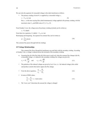
For example, if the transformer has a turns ratio a = 1/2,
the voltage V2 = 2 V1, current I2 = 0.5 I1 as shown below.
Primary voltage and current Secondary voltage and current
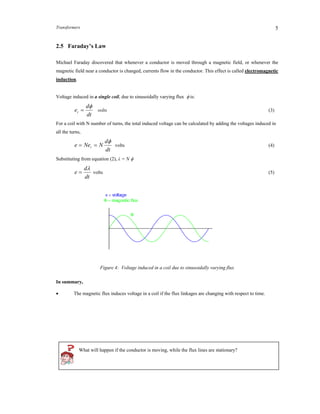
Figure 11: Voltage and current waveforms
Is there any limit to the magnitude of voltage increase/decrease in a transformer?
• What changes will have to be made if we wanted to switch primary and secondary sides,
i.e., apply the supply voltage on the right hand side in figure 10, while the load is
connected on the left hand side?
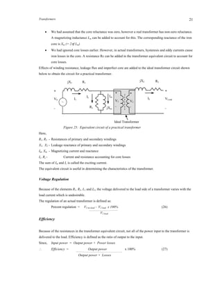
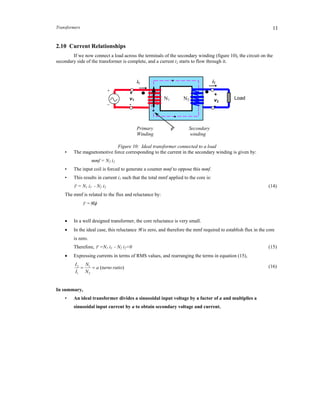
2.11 Ideal Transformer – Equivalent Circuit
The equivalent circuit (i.e., without the magnetic core) of an ideal transformer can be drawn as follows.
The equivalent circuit is used for determining the performance characteristics of the transformer.
Figure. 12: Ideal transformer equivalent circuit
[Note that the voltage and current relationships remain the same whether they are shown in their instantaneous
values or RMS values.]
Let’s consider some cases. The transformer equivalent circuits for these cases are shown in figure 13.
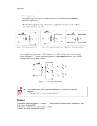
If a < 1, i.e. N1 < N2
The output voltage is greater than the input voltage and the transformer is called a step-up transformer
(figure 13(a)).
If a > 1, i.e. N1 > N2
The output voltage is smaller than the input voltage and the transformer is called a step-down
transformer (figure 13(b)).
voltage current
voltage
current
V1
I1
N1 V2N2
I2 = aI1
V1 =aV 2
13. Transformers 13
If a = 1, i.e. N1 = N2
The output voltage is the same as the input voltage and the transformer is called an isolation
transformer (figure 13(c)).
These transformers perform a very useful function for applications where two circuits need to be
electrically isolated from each other.
Figure 13(a): Step-up transformer Figure 13(b): Step-down transformer Figure 13(c): Isolation transformer
In many applications, the secondary winding is tapped at two different points, giving rise to two output
circuits (see figure 14). The most common configuration is centre-tapped transformer which splits the
secondary voltage into two equal voltages.
Figure 14: Centre-tapped transformer
Can you think of some specific applications where there is a need to use an isolation
transformer?
What applications use centre-tapped transformers?
Example 2:
A transformer is required to deliver 1A current at 12 V from a 240 V RMS supply voltage. The number of turns
in the primary winding is 2000.
(i) How many turns are required in the secondary winding?
(ii) what is the current in the primary winding?
N
2
N1
N
3
N
1
V
1
V
1
2
3
V
2 =
V
3 =
N1
N
2
N
3
+
_
_
+
_
+
V1
V
V
I1
V1
I1
N1 N
2
V2
N1 N
2
V1
V2
I1
N
2
V2V1
I1
N1
14. Transformers14
Solution:
Here, V1 = 240 V; V2 = 12 V;
I2 = 1 A; N1 = 2000
(i) Using equation (13), the number of turns in the secondary winding:
turns
V
V
NN 100
240
12
2000
1
2
12
The turns ratio, a = 20 (i.e., this is a step-down transformer)
(ii) From equation (16), the primary current:
1
2000
100
2
1
2
1 I
N
N
I 50 mA
2.12 Power in an Ideal Transformer
The power delivered to the load by the secondary winding:
222 .ivp (17)
(Note that the lower case letter (e.g. p, v, or i ) refers to the time-varying instantaneous value of an ac wave.)
Using equations for v2 and i2 and substituting in the above equation,
1212
1
iaiandv
a
v ,
11112 ..
1
iviav
a
p
(18)
However, the power delivered to the primary winding by the source is :
111 .ivp (19)
Therefore, p1 = p2 (20)
i.e., Power input = Power output
In terms of RMS values, P1 = P2
In summary,
• The net power is neither generated nor consumed by an ideal transformer.
• The losses are zero in an ideal transformer.
• If a transformer increases the voltage, the current decreases and vice versa.
Application Example: Power distribution systems
AC electricity is generated in power stations at medium voltage levels (i.e., something like 11kV), and is
consumed by the domestic user at an RMS voltage of 220V (in Singapore). The electricity generated at the
power station is fed into a step-up transformer which boosts its peak voltage from a few kilo volts to many tens
of kilovolts. The output from the step-up transformer is fed into a high tension transmission line, which typically
15. Transformers 15
transports the electricity over many tens of kilometers, and, once the electricity has reached its point of
consumption, it is fed through a series of step-down transformers until, by the time it emerges from a domestic
plug, its RMS voltage is only 220V. The process can be shown using a simple block diagram as follows:
Figure15: Transformers raise/lower voltages in electrical energy distribution
But, if AC electricity is generated and consumed at comparatively low voltages, why go to the
trouble of stepping up the voltage to a very high value at the power station and then stepping
down the voltage again once the electricity has reached its point of consumption? Why not
generate, transmit, and distribute the electricity at 220V?
Why is AC more widely used compared to DC?
2.13 Transformer rating
The transformer is usually rated in terms of its input and output voltages and apparent power that it is designed
to safely deliver.
For example, if a transformer carries the following information on its name-plate:
10kVA, 1100/110volts
What are the meanings of these ratings?
The voltage ratio indicates that the transformer has two windings, the high-voltage winding is rated for 1100
Volts and the low-voltage winding for 110 volts.
These voltages are proportional to their respective number of turns. Therefore, the voltage ratio also represents
the turns ratio a. (e.g., a = 10 here)
The kVA rating (i.e., apparent power) means that each winding is designed for 10 kVA.
Therefore the current rating for the high-voltage winding = 10000/1100 = 9.09A
Power
generating
station
Power
transmiss
-ion
Power
distribution Home
11kV 220kV 220kV 22kV 22kV 220V
16. Transformers16
Current rating for low voltage winding = 10000/110 = 90.9 A
The term “rated load” for a device refers to the load it is designed to carry for (theoretically) indefinite period
of time. Rated load for the transformer refers to the apparent power specified as above, and shown in the name-
plate information.
Note that during actual operation, the transformer may be required to operate at less power than its rated
power.
2.14 Impedance transformation
Consider the following circuit, where a load impedance ZL is connected in the secondary winding. The RMS
values of current and voltage in the secondary winding are related to the impedance by:
2
2
I
V
ZL (23)
Substituting for V2 and I2,
1
1
2
1
2
121
112
)/(
)/(
I
V
N
N
INN
VNN
ZL
(24)
Rearranging this equation, and substituting a = N1/N2, the impedance seen by the source, Z’L is given by:
LL Za
I
V
Z 2
1
1
' (25)
i.e., When a load impedance Z L is connected across the secondary winding terminals, the AC source connected
on the input side sees the load impedance magnified by the factor a2
.
We say that the load impedance is reflected or referred to the primary side by the square of the turns ratio a.
Figure 16: Load impedance as seen by the source
ZL
Z’L
N1: N2
+
_
~VS
I1 I2
+
V2
_
17. Transformers 17
This circuit can be simplified as follows:
Figure 17: Simplified circuit
In a similar manner, it can be shown that if an impedance is connected on the source side of the circuit (as
shown below), the load sees it changed by a factor of (1/ a2
).
Figure 18: Source impedance as seen by the load
If we look at this circuit from the load side (i.e., as seen by the load), the voltage of the source and the
impedance appear changed as shown below.
Figure 19: Simplified circuit
Application Example: Impedance Matching
A very important application of transformers is as an impedance matching device using the concept of “reflected
load”.
+
a.V2
_
ZS
Reflected load
impedance
Z’L=a2
ZL
+
_~VS
I1
ZL
Reflected source
impedance
~
(1/a2
)ZS
(1/a)VS
ZL
Z
+_~VS
ZS
Z”S = (1/ a2
) ZS
18. Transformers18
Recall that the maximum power transfer theorem states that a power source delivers maximum power to the load
when the load resistance is equal to the internal resistance of the source. This can be accomplished by using a
transformer to match the two resistances.
Figure 20: Transformer application for impedance matching
Thus, by choosing the appropriate turns ratio for the transformer in equation (25), the effective load resistance
R’L can be made equal to the internal resistance of the source, no matter what value the actual load resistance RL
takes. This process is called impedance matching. A practical example of impedance matching in given below.
Example 3:
For example, if the internal resistance of the source is 75, and the resistance of the load is 300, a transformer
with turns ratio of 1:2 can be used for impedance matching as shown below.
Figure 21: Impedance matching
The maximum power transfer from an active device like an amplifier to an external device like a speaker will
occur when the impedance of the external device matches that of the source. Transformers are used for this
purpose. Improper impedance matching can lead to excessive power use, distortion, and noise problems.
ZL
+_~ VS
Source
impedanc
Load
resistance
RLoad
PLoad Rsource = RLoad
_~VS
1:2
75
ZL300
19. Transformers 19
Example 4:
For the circuit shown below, find the phasor currents and voltages, and the power delivered to the load.
Figure 22: Transformer equivalent circuit for example 4
The load impedance reflected to (i.e., seen by) the primary side:
ohmsjZ
N
N
Z LL )2010()10(' 2
2
2
1
The total impedance seen by the source is:
ZS = R1 + Z’L = 1000 + 1000 + j2000 = 282845o
ohms
Figure 23: Simplified circuit
The primary current and voltage can be calculated as:
A
Z
V
I
s
s 0
0
0
1 453536.0
452828
01000
V1 = I1Z’L = 0.3536-45o
x (1000 + j2000)
= 790.618.43o
V
Using the turns ratio, we can calculate secondary side voltage and current as follows:
AI
N
N
I 00
1
2
1
2 45536.3453536.0
1
10
VV
N
N
V 00
1
1
2
2 43.1806.79)43.186.790(
10
1
The power delivered to the load:
WRIP LL 0331.125)10()536.3()( 22
2
What is the power consumed in the reactive part of the load?
VS=10000o
Volts ZL=10+j20
10:1
~
R1=1000 I2 I1
+
V2
_
+
V1
_
I1
+
V1
_
Reflected load
Impedance
100 (10 + j20) ohms
~10000o
Volts
20. Transformers20
Application Example: Power Supply Circuits
Transformers are an integral part of all power supplies. A typical application example of AC-DC power supply
is shown below, where transformer is used for lowering the voltage to a level more suitable for consumption.
This voltage is then rectified and filtered to obtain a DC voltage.
Figure 24: Block diagram of a power supply
Aside from the ability to easily convert between different levels of voltage and current in AC and DC circuits,
transformers also provide an extremely useful feature called isolation, which is the ability to couple one circuit
to another without the use of direct wire connections.
What type of transformer will result if there is only one winding in the transformer?
Why does the transformer used in power supplies gets heated after a few hours in operation?
What would happen if a transformer is connected across DC supply voltage?
2.15 Actual (Non-ideal) Transformer
Recall that we had made several assumptions when analyzing an ideal transformer. An actual transformer
differs from an ideal transformer in that is has:
Resistive (I2
R) losses (also called copper losses) in the primary and secondary windings
Not all the flux produced by the primary winding links the secondary winding, and vice versa. This
gives rise to some leakage of flux.
The core requires a finite amount of mmf for its magnetization.
Hysteresis and eddy current losses cause power loss in transformer core.
The equivalent circuit of an ideal transformer can be modified to include these effects.
Resistances R1 and R2 can be added on both primary and secondary side to represent the actual winding
resistances.
The effect of leakage flux can be included by adding two inductances L1 and L2 respectively, in the
primary and secondary winding circuits.
Transformer Rectifier
bridge
Filter
And
regulator
AC input
voltage DC output
voltage
21. Transformers 21
We had assumed that the core reluctance was zero, however a real transformer has non-zero reluctance.
A magnetizing inductance Lm can be added to account for this. The corresponding reactance of the iron
core is Xm (= 2f Lm)
We had ignored core losses earlier. However, in actual transformers, hysteresis and eddy currents cause
iron losses in the core. A resistance Rc can be added in the transformer equivalent circuit to account for
core losses.
Effects of winding resistance, leakage flux and imperfect core are added to the ideal transformer circuit shown
below to obtain the circuit for a practical transformer.
Figure 25: Equivalent circuit of a practical transformer
Here,
R1, R2 - Resistances of primary and secondary windings
X1, X2 - Leakage reactance of primary and secondary windings
Im, Xm - Magnetizing current and reactance
Ic, Rc - Current and resistance accounting for core losses
The sum of Im and Ic is called the exciting current.
The equivalent circuit is useful in determining the characteristics of the transformer.
Voltage Regulation
Because of the elements R1, R2, L1 and L2, the voltage delivered to the load side of a transformer varies with the
load current which is undesirable.
The regulation of an actual transformer is defined as:
Percent regulation = V2 no-load - V2 load x 100% (26)
V2 load
Efficiency
Because of the resistances in the transformer equivalent circuit, not all of the power input to the transformer is
delivered to the load. Efficiency is defined as the ratio of output to the input.
Since, Input power = Output power + Power losses
Efficiency = Output power x 100% (27)
Output power + Losses
+
VS
_
R2jX2
+
VLoad
_
Ideal Transformer
I1
jX1
Ic
+
V1
_
I2
+
V2
_
R1
Im
Rc jXm
~