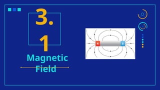
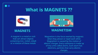
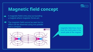
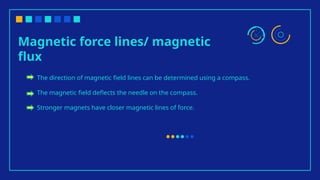
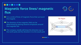
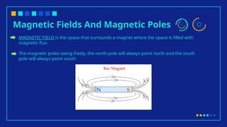
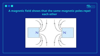
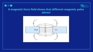
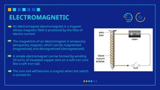
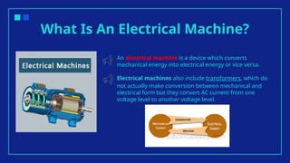
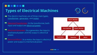
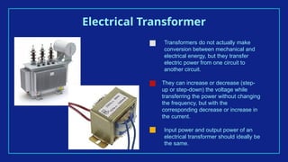
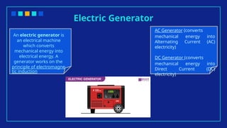
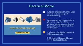
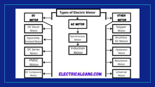
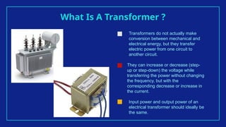
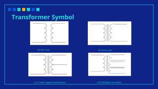
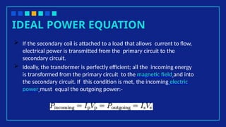
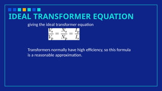
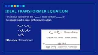
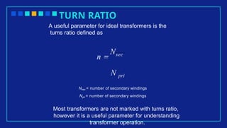
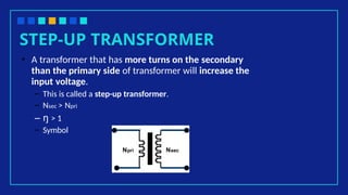
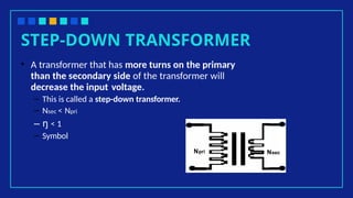
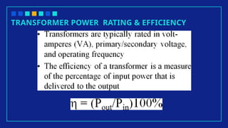
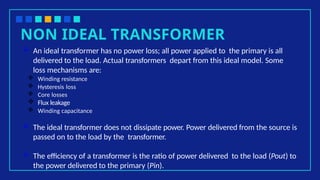
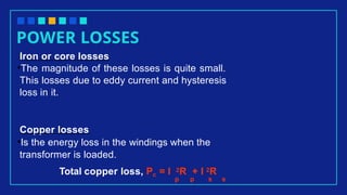
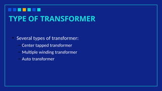
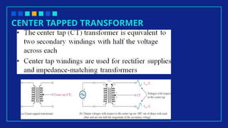
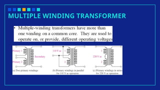
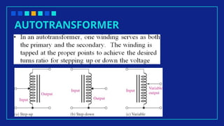
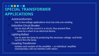
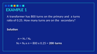
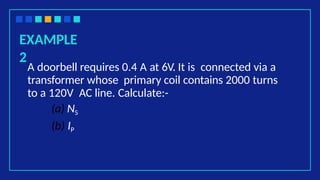
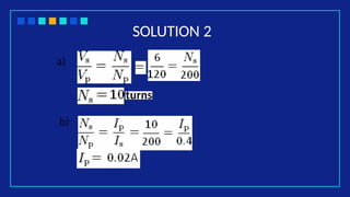
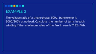
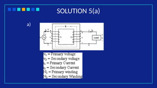
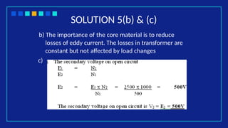
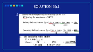
Chapter 3:
Electromagnetic
Fundamentals
Table of contents
3.1
3.3
3.2
3.4
Elaborate
magnetic
field
Explain type
of
transformer
Explain
electric
machines
Elaborate the
principle of
the
transformer
Magnetic
Field
3.
1
What is MAGNETS ??
A magnet is a metal or rock
that can attract objects
containing iron, nickel, cobalt
or a mixture of these metals
Magnetism is the force exerted by magnets
when they attract or repel each other.
Magnetism is caused by the motion of
electric charges. Every substance is made up
of tiny units called atoms. Each atom has
electrons, particles that carry electric
charges.
MAGNETS MAGNETISM
Characteristics of magnetic materials
The magnetic field
exists in the area around
the magnet and the
space is filled with
magnetic flux
The magnetic flux is the
circle of magnetic field
lines
The magnetic poles
consist of a north pole
and a south pole
1 3
2
Magnetic field concept
A magnetic field is the area surrounding
a magnet where magnetic forces act.
The magnetic field cannot be seen but its
effect can be observed using iron powder
and a compass.
magnetic field lines move
from the north pole to the
south pole of the magnet
Magnetic force lines/ magnetic
flux
The direction of magnetic field lines can be determined using a compass.
The magnetic field deflects the needle on the compass.
Stronger magnets have closer magnetic lines of force.
Magnetic force lines/ magnetic
flux
It is a circle of lines of magnetic force that surround
the magnet.
The direction of the magnetic field can be
determined by placing several compasses around
the magnetic bar.
The compass needle will show the direction out of
the north pole and the direction in to the south pole
Magnetic Fields And Magnetic Poles
MAGNETIC FIELD is the space that surrounds a magnet where the space is filled with
magnetic flux.
The magnetic poles swing freely, the north pole will always point north and the south
pole will always point south.
A magnetic field shows that the same magnetic poles repel
each other
A magnetic force field shows that different magnetic poles
attract
SAME MAGNETIC
POLES
DIFFERENT MAGNETIC
POLES
ELECTROMAGNETIC
An electromagnet (electromagnet) is a magnet
whose magnetic field is produced by the flow of
electric current.
The magnetism of an electromagnet is temporary
(temporary magnet), which can be magnetised
(magnetised) and demagnetised (demagnetised).
A simple electromagnet can be formed by winding
20 turns of insulated copper wire on a soft iron core
like a soft iron nail.
The iron nail will become a magnet when the switch
is turned on.
Electric
Machines
3.2
What Is An Electrical Machine?
An electrical machine is a device which converts
mechanical energy into electrical energy or vice versa.
Electrical machines also include transformers, which do
not actually make conversion between mechanical and
electrical form but they convert AC current from one
voltage level to another voltage level.
Types of Electrical Machines
The electric machines are of three main types,
transformer, generator, and motor.
Electrical Transformer: In the transformer, both
input and output are electrical power.
Electrical Generator: In a generator, the input is
mechanical power and the output is electrical
power.
Electrical Motor: In a motor, the input is electrical
power and output is mechanical power.
Electrical Transformer
Transformers do not actually make
conversion between mechanical and
electrical energy, but they transfer
electric power from one circuit to
another circuit.
They can increase or decrease (step-
up or step-down) the voltage while
transferring the power without changing
the frequency, but with the
corresponding decrease or increase in
the current.
Input power and output power of an
electrical transformer should ideally be
the same.
Electric Generator
An electric generator is
an electrical machine
which converts
mechanical energy into
electrical energy. A
generator works on the
principle of electromagne
tic induction
AC Generator (converts
mechanical energy into
Alternating Current (AC)
electricity)
DC Generator (converts
mechanical energy into
Direct Current (DC)
electricity)
Electrical Motor
A motor is an electrical machine which
converts electrical energy into
mechanical energy.
When a current carrying conductor is
placed in a magnetic field, the
conductor experiences a mechanical
force and this is the principle behind
motoring action.
1. AC motors: (i)Induction motors and
(ii) Synchronous motor
2. DC motors: (i) Brushed DC motor
and (ii) Brushless DC motor
Types of Electical Motor
AC Motor DC Motor Special Purpose
Motor
Transformer
3.3
What Is A Transformer ?
Transformers do not actually make
conversion between mechanical and
electrical energy, but they transfer
electric power from one circuit to
another circuit.
They can increase or decrease (step-
up or step-down) the voltage while
transferring the power without changing
the frequency, but with the
corresponding decrease or increase in
the current.
Input power and output power of an
electrical transformer should ideally be
the same.
Transformer Symbol
(a) Air core (b) Iron core
(d) Multiple secondary
(c) Center tapped transformer
THE BASIC TRANSFORMER
•Source voltage is applied to the primary winding
•The load is connected to the secondary winding
•The core provided a physical structure for placement of windings and a
magnetic path so that the magnetic flux lines are concentrated close to
the coils
•Typical core materials are : air, ferrite and iron
TRANSFORMER
BASICS
▪ When an AC voltage is applied in a
coil, the electromagnetic field
expands, collapses and reverses as
the current increases, decreases
and reverses.
▪ When two coils are placed very close
to each other, the changing magnetic
field produced by the first coil will
cause an induced voltage in the
second coil because of the mutual
inductance between the two coil.
HOW???
▪ When two coils are placed very
close to each other, the
changing magnetic flux line
produced by the first coil will
cut through the second coil.
The two coils are said to be
magnetically linked or
coupled. As a result, a voltage
is induced.
TRANSFORMER BASICS
The parts of an ideal transformer
BASIC PRINCIPLES
 The transformer is based on two principles:
 first, that an electric current can produce a magnetic field (electromagnetism), and
 second that a changing magnetic field within a coil of wire induces a voltage across the ends of
the coil (electromagnetic induction).
 Changing the current in the primary coil changes the
 magnetic flux that is developed.
 The changing magnetic flux induces a voltage in the secondary coil.
 Current passing through the primary coil creates a magnetic field.
 The primary and secondary coils are wrapped around a core of very high magnetic permeability, such
as iron, so that most of the magnetic flux passes through both the primary and secondary coils.
TRANSFORMER CONSTRUCTION
 The transformer consists of core, surrounded by at least two series
of coils.
 The core is used as to aid in linking the flux from the primary
coil to the secondary coil.
 Dots are used in diagrams of transformers to indicate the current
polarities for the windings.
 Dotted terminals have the same polarity.
(a) Voltage are in phase (b) Voltage are out of
phase
Dot Notation
THE FUNCTION
▪ Function of a transformer:
▪ To transfer current, voltage and power from one series of
windings (coils) to another.
INDUCTION LAW
• Taking the ratio of the two equations for Vs and Vp
gives the basic equation for stepping up or stepping
down the voltage
IDEAL POWER EQUATION
 If the secondary coil is attached to a load that allows current to flow,
electrical power is transmitted from the primary circuit to the
secondary circuit.
 Ideally, the transformer is perfectly efficient; all the incoming energy
is transformed from the primary circuit to the magnetic field and into
the secondary circuit. If this condition is met, the incoming electric
power must equal the outgoing power:-
IDEAL TRANSFORMER EQUATION
giving the ideal transformer equation
Transformers normally have high efficiency, so this formula
is a reasonable approximation.
For an ideal transformer, the PPrimary is equal to the PSecondary, or
the power input is equal to the power output.
Pout = Pin VsIs
= VpIp Is/Ip =
Vp/Vs
Efficiency of transformer,
IDEAL TRANSFORMER EQUATION
TURN RATIO
A useful parameter for ideal transformers is the
turns ratio defined as
n =
Nsec
N pri
Nsec = number of secondary windings
Npri = number of secondary windings
Most transformers are not marked with turns ratio,
however it is a useful parameter for understanding
transformer operation.
STEP-UP TRANSFORMER
• A transformer that has more turns on the secondary
than the primary side of transformer will increase the
input voltage.
– This is called a step-up transformer.
– Nsec > Npri
– ŋ > 1
– Symbol
Npri Nsec
DC ISOLATION
STEP-DOWN TRANSFORMER
• A transformer that has more turns on the primary
than the secondary side of the transformer will
decrease the input voltage.
– This is called a step-down transformer.
– Nsec < Npri
– ŋ < 1
– Symbol
Npri Nsec
REFLECTED LOAD
TRANSFORMER POWER RATING & EFFICIENCY
NON IDEAL TRANSFORMER
 An ideal transformer has no power loss; all power applied to the primary is all
delivered to the load. Actual transformers depart from this ideal model. Some
loss mechanisms are:
 Winding resistance
 Hysteresis loss
 Core losses
 Flux leakage
 Winding capacitance
 The ideal transformer does not dissipate power. Power delivered from the source is
passed on to the load by the transformer.
 The efficiency of a transformer is the ratio of power delivered to the load (Pout) to
the power delivered to the primary (Pin).
POWER LOSSES
Iron or core losses
•The magnitude of these losses is quite small.
This losses due to eddy current and hysteresis
loss in it.
Copper losses
•Is the energy loss in the windings when the
transformer is loaded.
Total copper loss, Pc = I 2R + I 2R
p p s s
TYPE OF TRANSFORMER
• Several types of transformer:
– Center tapped transformer
– Multiple winding transformer
– Auto transformer
CENTER TAPPED TRANSFORMER
MULTIPLE WINDING TRANSFORMER
AUTOTRANSFORMER
TRANSFORMER APPLICATION
– Step-up or step-down voltage and current.
– Isolation device
» electrical isolation. Electrical isolation can be used to improve
the safety of electrical equipment.
» DC isolation. Coupling transformers can be used to block DC
signals from reaching the secondary circuit.
– Impedance matching for max power transfer
SPECIAL TRANSFORMER
APPLICATIONS
 Autotransformers
• Use in low-voltage applications since has only one winding.
 Induction Circuit Breaker
• Use to shut off the current in a circuit, thus prevent fires
• cause by a short in an electrical device.
 Lighting Ballast
• Use to start the lamp by producing the necessary voltage and limits
current thro the lamp.
 Coupling Transformer
• Isolates each section of the amplifier – so individual amplifier
characteristics will not interfere with others
EXAMPLE 1
A transformer has 800 turns on the primary and a turns
ratio of 0.25. How many turns are on the secondary?
Solution
n = Ns / Np
NS = Np x n = 800 x 0.25 = 200 turns
EXAMPLE
2
A doorbell requires 0.4 A at 6V. It is connected via a
transformer whose primary coil contains 2000 turns
to a 120V AC line. Calculate:-
(a) NS
(b) IP
SOLUTION 2
a)
b)
EXAMPLE 3
The voltage ratio of a single-phase, 50Hz transformer is
5000/500V at no load. Calculate the number of turns in each
winding if the maximum value of the flux in core is 7.82mWb.
SOLUTION 3
Ep=Vp=5000V, Es=Vs=500V, Øm=7.82mWb
Ep = 4.44 f Øm Np
Np = Ep / 4.44 f Øm = 5000 / (4.44 x 50 x 7.82m)
= 2880 turns
EXAMPLE
4
A single transformer is connected to a 660V supply. The
voltage/turn of the transformer is 1.1V. The secondary voltage
of the transformer is found to be 440V. Determine the
following:-
a)Primary and secondary turns
b)Cross-section of the core if the maximum flux density is 1.4T
SOLUTION 4
Voltage/turn=1.1V, Vp=660V, Vs=440V, Bmax=1.4T
i) Np = Vp / 1.1 = 660 / 1.1 = 600 turns
Ns = Vs / 1.1 = 440 / 1.1 = 400 turns
ii) Ep = 4.44 f Øm Np Øm = Bmax
A
A = Vp / 4.44 f Bmax Np
= 660 / (4.44 x 50 x 1.4 x 600)
= 35.39 x 10⁻⁴ m2 = 35.39cm2
EXAMPLE
5
a) Illustrate the parts of an ideal transformer.(5m)
b) Identify the importance of the core material. (3m)
c) A 50 kVA, single-phase transformer has 500 turns on the primary and
100 turns on the secondary. The primary is connected to 2500V,
50Hz supply. Calculate the following :- (9m)
i) The secondary voltage on open circuit
ii) The current flowing through the windings on full load
iii) The maximum value of flux
d) A single phase ideal transformer contains 3000 circumferences at
primary coil and 800 circumferences at secondary coil. Primary coil
is connected to 240VAC, 50Hz supply. Calculate:- (8m)
i) Secondary voltage
ii) Current on secondary coil if the current on primary coil is 5A.
iii) Transformer power on primary and secondary coils
SOLUTION 5(a)
a)
SOLUTION 5(b) & (c)
b) The importance of the core material is to reduce
losses of eddy current. The losses in transformer are
constant but not affected by load changes
c)
SOLUTION 5(c)
c)
SOLUTION 5(d)
d)

TOPIC 3 : Electromagnetic Fundamentals (DAD10042)

  • 1.
  • 2.
    Table of contents 3.1 3.3 3.2 3.4 Elaborate magnetic field Explaintype of transformer Explain electric machines Elaborate the principle of the transformer
  • 3.
  • 4.
    What is MAGNETS?? A magnet is a metal or rock that can attract objects containing iron, nickel, cobalt or a mixture of these metals Magnetism is the force exerted by magnets when they attract or repel each other. Magnetism is caused by the motion of electric charges. Every substance is made up of tiny units called atoms. Each atom has electrons, particles that carry electric charges. MAGNETS MAGNETISM
  • 5.
    Characteristics of magneticmaterials The magnetic field exists in the area around the magnet and the space is filled with magnetic flux The magnetic flux is the circle of magnetic field lines The magnetic poles consist of a north pole and a south pole 1 3 2
  • 6.
    Magnetic field concept Amagnetic field is the area surrounding a magnet where magnetic forces act. The magnetic field cannot be seen but its effect can be observed using iron powder and a compass. magnetic field lines move from the north pole to the south pole of the magnet
  • 7.
    Magnetic force lines/magnetic flux The direction of magnetic field lines can be determined using a compass. The magnetic field deflects the needle on the compass. Stronger magnets have closer magnetic lines of force.
  • 8.
    Magnetic force lines/magnetic flux It is a circle of lines of magnetic force that surround the magnet. The direction of the magnetic field can be determined by placing several compasses around the magnetic bar. The compass needle will show the direction out of the north pole and the direction in to the south pole
  • 9.
    Magnetic Fields AndMagnetic Poles MAGNETIC FIELD is the space that surrounds a magnet where the space is filled with magnetic flux. The magnetic poles swing freely, the north pole will always point north and the south pole will always point south.
  • 10.
    A magnetic fieldshows that the same magnetic poles repel each other
  • 11.
    A magnetic forcefield shows that different magnetic poles attract
  • 12.
  • 13.
    ELECTROMAGNETIC An electromagnet (electromagnet)is a magnet whose magnetic field is produced by the flow of electric current. The magnetism of an electromagnet is temporary (temporary magnet), which can be magnetised (magnetised) and demagnetised (demagnetised). A simple electromagnet can be formed by winding 20 turns of insulated copper wire on a soft iron core like a soft iron nail. The iron nail will become a magnet when the switch is turned on.
  • 14.
  • 15.
    What Is AnElectrical Machine? An electrical machine is a device which converts mechanical energy into electrical energy or vice versa. Electrical machines also include transformers, which do not actually make conversion between mechanical and electrical form but they convert AC current from one voltage level to another voltage level.
  • 16.
    Types of ElectricalMachines The electric machines are of three main types, transformer, generator, and motor. Electrical Transformer: In the transformer, both input and output are electrical power. Electrical Generator: In a generator, the input is mechanical power and the output is electrical power. Electrical Motor: In a motor, the input is electrical power and output is mechanical power.
  • 17.
    Electrical Transformer Transformers donot actually make conversion between mechanical and electrical energy, but they transfer electric power from one circuit to another circuit. They can increase or decrease (step- up or step-down) the voltage while transferring the power without changing the frequency, but with the corresponding decrease or increase in the current. Input power and output power of an electrical transformer should ideally be the same.
  • 18.
    Electric Generator An electricgenerator is an electrical machine which converts mechanical energy into electrical energy. A generator works on the principle of electromagne tic induction AC Generator (converts mechanical energy into Alternating Current (AC) electricity) DC Generator (converts mechanical energy into Direct Current (DC) electricity)
  • 19.
    Electrical Motor A motoris an electrical machine which converts electrical energy into mechanical energy. When a current carrying conductor is placed in a magnetic field, the conductor experiences a mechanical force and this is the principle behind motoring action. 1. AC motors: (i)Induction motors and (ii) Synchronous motor 2. DC motors: (i) Brushed DC motor and (ii) Brushless DC motor
  • 21.
    Types of ElecticalMotor AC Motor DC Motor Special Purpose Motor
  • 22.
  • 23.
    What Is ATransformer ? Transformers do not actually make conversion between mechanical and electrical energy, but they transfer electric power from one circuit to another circuit. They can increase or decrease (step- up or step-down) the voltage while transferring the power without changing the frequency, but with the corresponding decrease or increase in the current. Input power and output power of an electrical transformer should ideally be the same.
  • 24.
    Transformer Symbol (a) Aircore (b) Iron core (d) Multiple secondary (c) Center tapped transformer
  • 25.
    THE BASIC TRANSFORMER •Sourcevoltage is applied to the primary winding •The load is connected to the secondary winding •The core provided a physical structure for placement of windings and a magnetic path so that the magnetic flux lines are concentrated close to the coils •Typical core materials are : air, ferrite and iron
  • 26.
    TRANSFORMER BASICS ▪ When anAC voltage is applied in a coil, the electromagnetic field expands, collapses and reverses as the current increases, decreases and reverses. ▪ When two coils are placed very close to each other, the changing magnetic field produced by the first coil will cause an induced voltage in the second coil because of the mutual inductance between the two coil. HOW???
  • 27.
    ▪ When twocoils are placed very close to each other, the changing magnetic flux line produced by the first coil will cut through the second coil. The two coils are said to be magnetically linked or coupled. As a result, a voltage is induced.
  • 28.
    TRANSFORMER BASICS The partsof an ideal transformer
  • 29.
    BASIC PRINCIPLES  Thetransformer is based on two principles:  first, that an electric current can produce a magnetic field (electromagnetism), and  second that a changing magnetic field within a coil of wire induces a voltage across the ends of the coil (electromagnetic induction).  Changing the current in the primary coil changes the  magnetic flux that is developed.  The changing magnetic flux induces a voltage in the secondary coil.  Current passing through the primary coil creates a magnetic field.  The primary and secondary coils are wrapped around a core of very high magnetic permeability, such as iron, so that most of the magnetic flux passes through both the primary and secondary coils.
  • 30.
    TRANSFORMER CONSTRUCTION  Thetransformer consists of core, surrounded by at least two series of coils.  The core is used as to aid in linking the flux from the primary coil to the secondary coil.  Dots are used in diagrams of transformers to indicate the current polarities for the windings.  Dotted terminals have the same polarity.
  • 31.
    (a) Voltage arein phase (b) Voltage are out of phase Dot Notation
  • 32.
    THE FUNCTION ▪ Functionof a transformer: ▪ To transfer current, voltage and power from one series of windings (coils) to another.
  • 33.
    INDUCTION LAW • Takingthe ratio of the two equations for Vs and Vp gives the basic equation for stepping up or stepping down the voltage
  • 34.
    IDEAL POWER EQUATION If the secondary coil is attached to a load that allows current to flow, electrical power is transmitted from the primary circuit to the secondary circuit.  Ideally, the transformer is perfectly efficient; all the incoming energy is transformed from the primary circuit to the magnetic field and into the secondary circuit. If this condition is met, the incoming electric power must equal the outgoing power:-
  • 35.
    IDEAL TRANSFORMER EQUATION givingthe ideal transformer equation Transformers normally have high efficiency, so this formula is a reasonable approximation.
  • 36.
    For an idealtransformer, the PPrimary is equal to the PSecondary, or the power input is equal to the power output. Pout = Pin VsIs = VpIp Is/Ip = Vp/Vs Efficiency of transformer, IDEAL TRANSFORMER EQUATION
  • 37.
    TURN RATIO A usefulparameter for ideal transformers is the turns ratio defined as n = Nsec N pri Nsec = number of secondary windings Npri = number of secondary windings Most transformers are not marked with turns ratio, however it is a useful parameter for understanding transformer operation.
  • 38.
    STEP-UP TRANSFORMER • Atransformer that has more turns on the secondary than the primary side of transformer will increase the input voltage. – This is called a step-up transformer. – Nsec > Npri – ŋ > 1 – Symbol Npri Nsec
  • 39.
  • 40.
    STEP-DOWN TRANSFORMER • Atransformer that has more turns on the primary than the secondary side of the transformer will decrease the input voltage. – This is called a step-down transformer. – Nsec < Npri – ŋ < 1 – Symbol Npri Nsec
  • 41.
  • 42.
  • 43.
    NON IDEAL TRANSFORMER An ideal transformer has no power loss; all power applied to the primary is all delivered to the load. Actual transformers depart from this ideal model. Some loss mechanisms are:  Winding resistance  Hysteresis loss  Core losses  Flux leakage  Winding capacitance  The ideal transformer does not dissipate power. Power delivered from the source is passed on to the load by the transformer.  The efficiency of a transformer is the ratio of power delivered to the load (Pout) to the power delivered to the primary (Pin).
  • 44.
    POWER LOSSES Iron orcore losses •The magnitude of these losses is quite small. This losses due to eddy current and hysteresis loss in it. Copper losses •Is the energy loss in the windings when the transformer is loaded. Total copper loss, Pc = I 2R + I 2R p p s s
  • 45.
    TYPE OF TRANSFORMER •Several types of transformer: – Center tapped transformer – Multiple winding transformer – Auto transformer
  • 46.
  • 47.
  • 48.
  • 49.
    TRANSFORMER APPLICATION – Step-upor step-down voltage and current. – Isolation device » electrical isolation. Electrical isolation can be used to improve the safety of electrical equipment. » DC isolation. Coupling transformers can be used to block DC signals from reaching the secondary circuit. – Impedance matching for max power transfer
  • 50.
    SPECIAL TRANSFORMER APPLICATIONS  Autotransformers •Use in low-voltage applications since has only one winding.  Induction Circuit Breaker • Use to shut off the current in a circuit, thus prevent fires • cause by a short in an electrical device.  Lighting Ballast • Use to start the lamp by producing the necessary voltage and limits current thro the lamp.  Coupling Transformer • Isolates each section of the amplifier – so individual amplifier characteristics will not interfere with others
  • 51.
    EXAMPLE 1 A transformerhas 800 turns on the primary and a turns ratio of 0.25. How many turns are on the secondary? Solution n = Ns / Np NS = Np x n = 800 x 0.25 = 200 turns
  • 52.
    EXAMPLE 2 A doorbell requires0.4 A at 6V. It is connected via a transformer whose primary coil contains 2000 turns to a 120V AC line. Calculate:- (a) NS (b) IP
  • 53.
  • 54.
    EXAMPLE 3 The voltageratio of a single-phase, 50Hz transformer is 5000/500V at no load. Calculate the number of turns in each winding if the maximum value of the flux in core is 7.82mWb.
  • 55.
    SOLUTION 3 Ep=Vp=5000V, Es=Vs=500V,Øm=7.82mWb Ep = 4.44 f Øm Np Np = Ep / 4.44 f Øm = 5000 / (4.44 x 50 x 7.82m) = 2880 turns
  • 56.
    EXAMPLE 4 A single transformeris connected to a 660V supply. The voltage/turn of the transformer is 1.1V. The secondary voltage of the transformer is found to be 440V. Determine the following:- a)Primary and secondary turns b)Cross-section of the core if the maximum flux density is 1.4T
  • 57.
    SOLUTION 4 Voltage/turn=1.1V, Vp=660V,Vs=440V, Bmax=1.4T i) Np = Vp / 1.1 = 660 / 1.1 = 600 turns Ns = Vs / 1.1 = 440 / 1.1 = 400 turns ii) Ep = 4.44 f Øm Np Øm = Bmax A A = Vp / 4.44 f Bmax Np = 660 / (4.44 x 50 x 1.4 x 600) = 35.39 x 10⁻⁴ m2 = 35.39cm2
  • 58.
    EXAMPLE 5 a) Illustrate theparts of an ideal transformer.(5m) b) Identify the importance of the core material. (3m) c) A 50 kVA, single-phase transformer has 500 turns on the primary and 100 turns on the secondary. The primary is connected to 2500V, 50Hz supply. Calculate the following :- (9m) i) The secondary voltage on open circuit ii) The current flowing through the windings on full load iii) The maximum value of flux d) A single phase ideal transformer contains 3000 circumferences at primary coil and 800 circumferences at secondary coil. Primary coil is connected to 240VAC, 50Hz supply. Calculate:- (8m) i) Secondary voltage ii) Current on secondary coil if the current on primary coil is 5A. iii) Transformer power on primary and secondary coils
  • 59.
  • 60.
    SOLUTION 5(b) &(c) b) The importance of the core material is to reduce losses of eddy current. The losses in transformer are constant but not affected by load changes c)
  • 61.
  • 62.