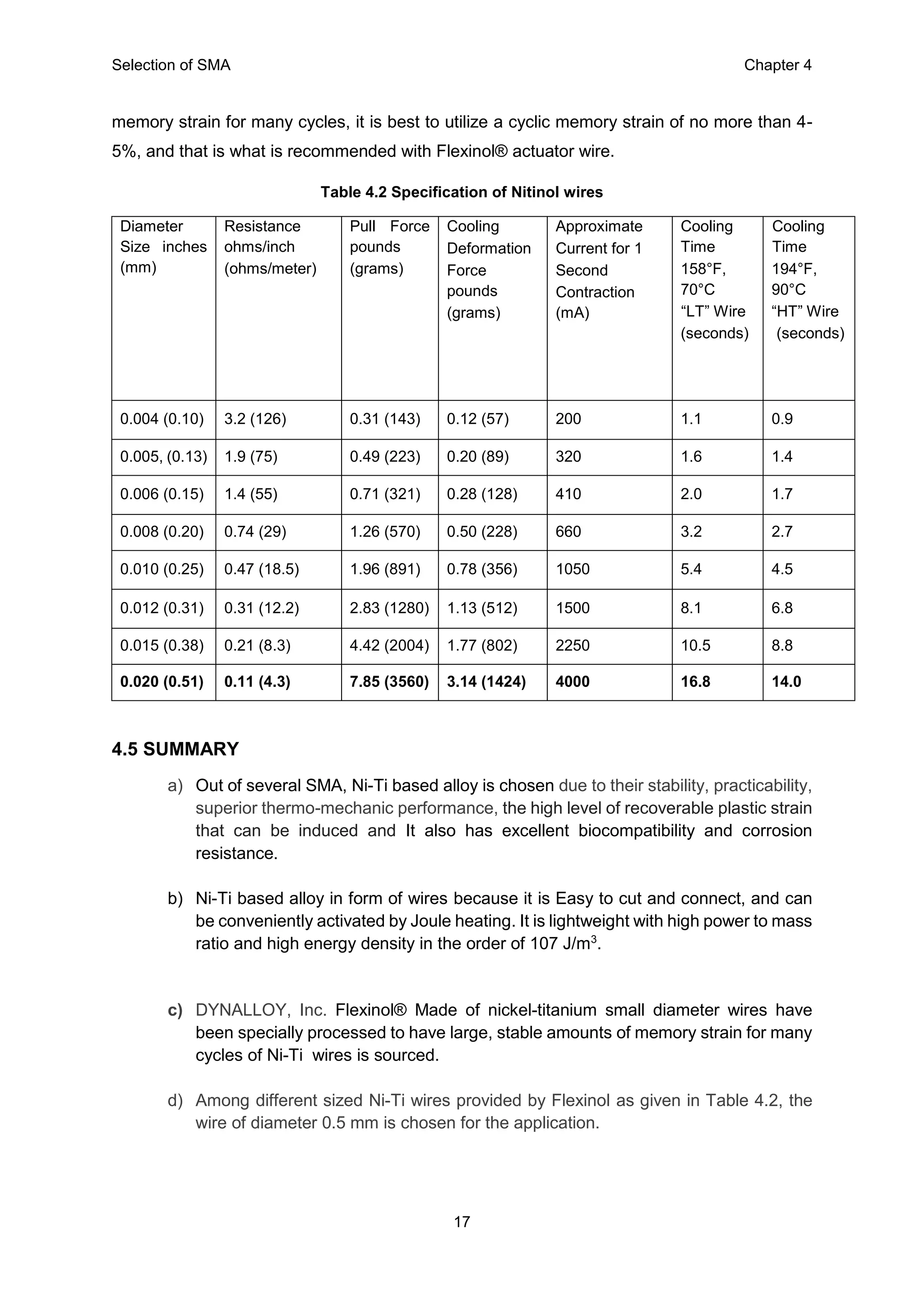
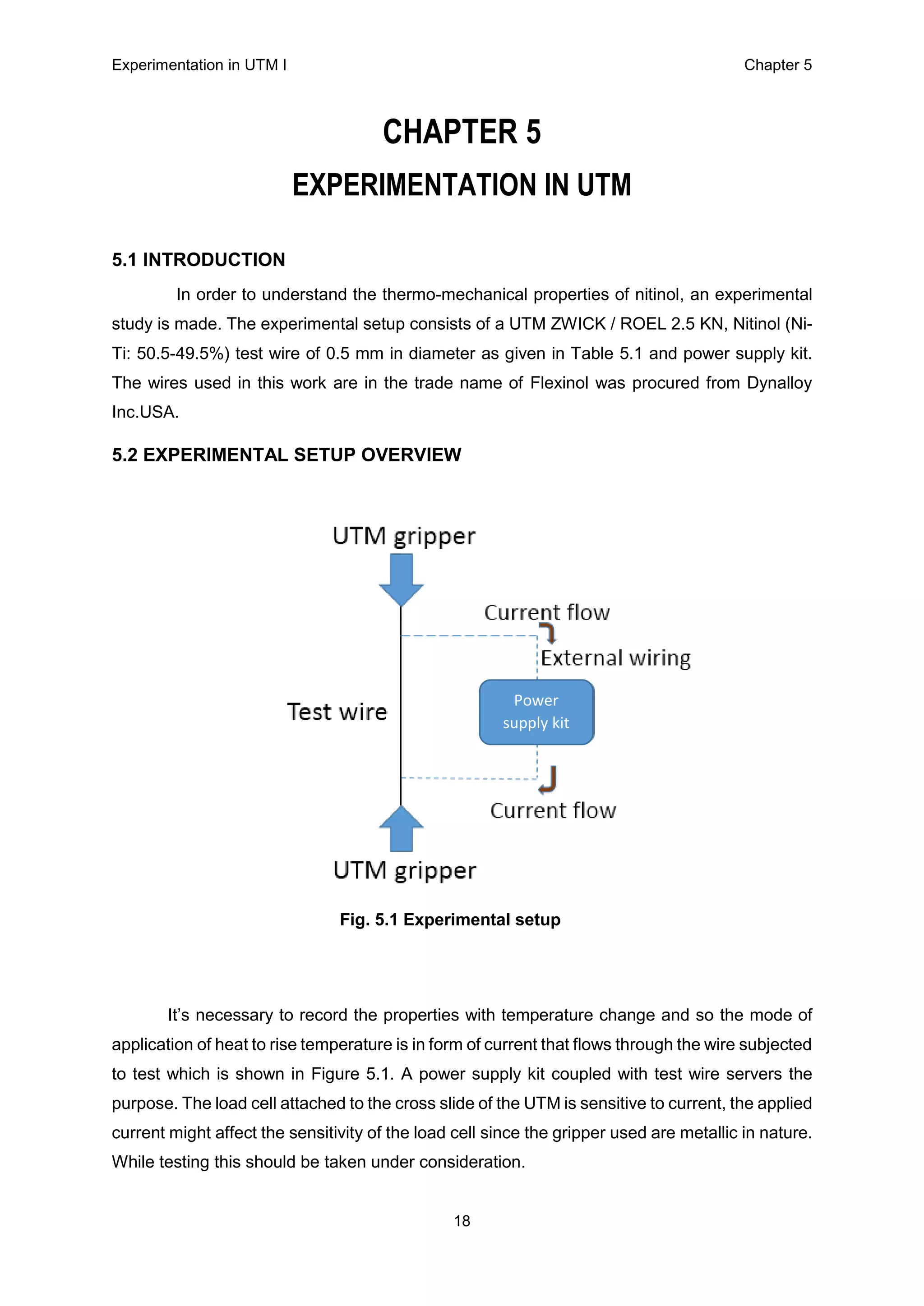
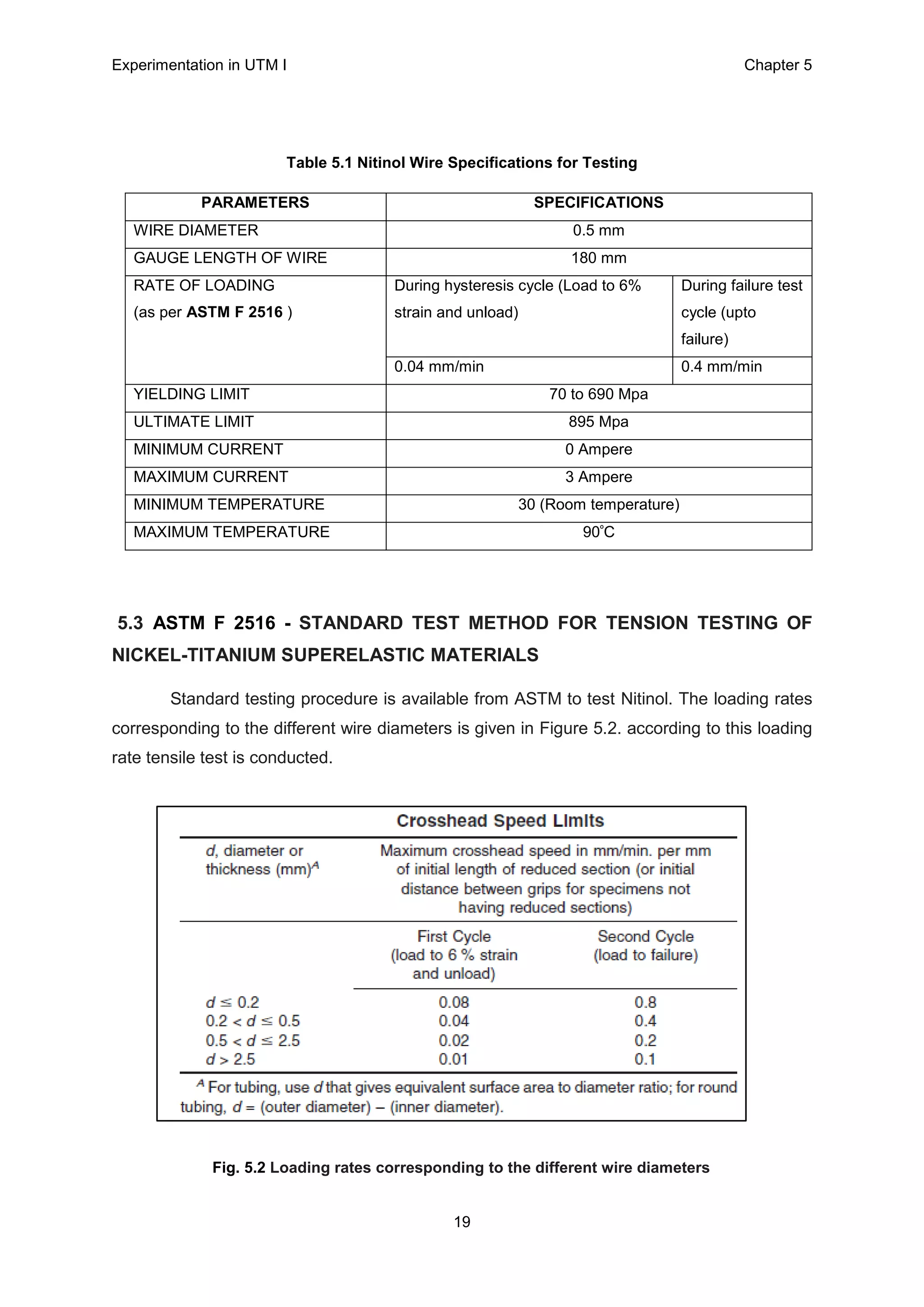
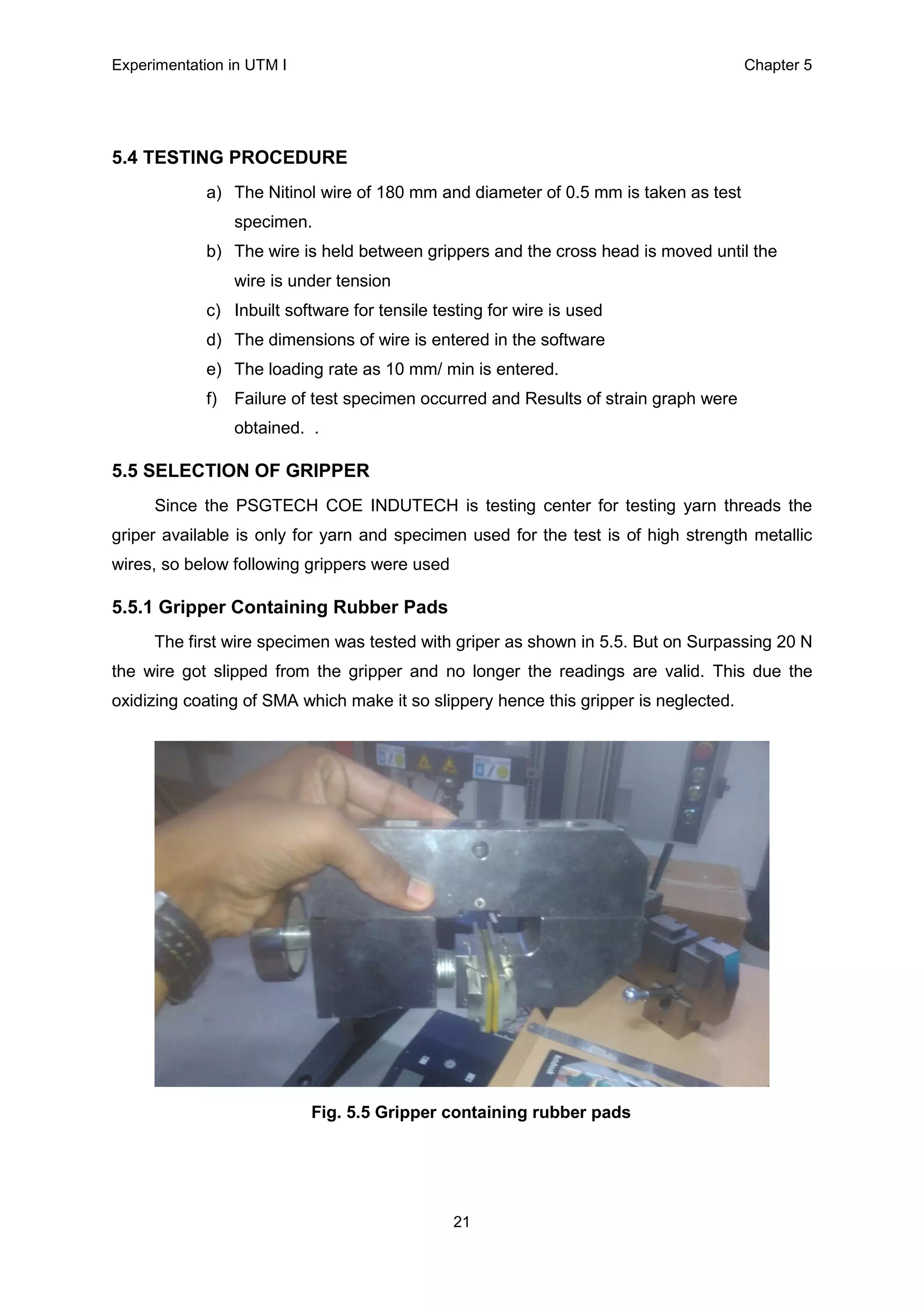
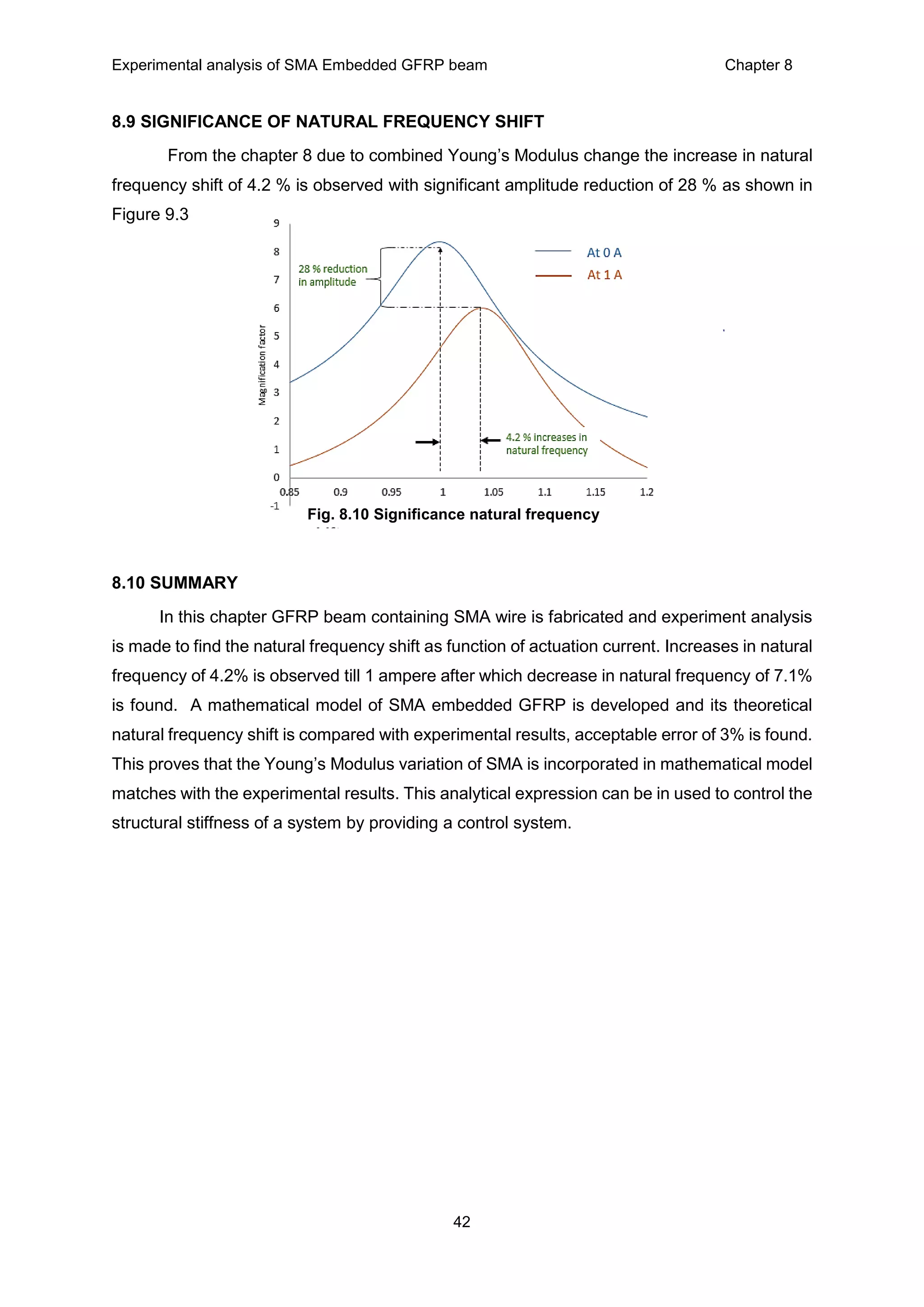
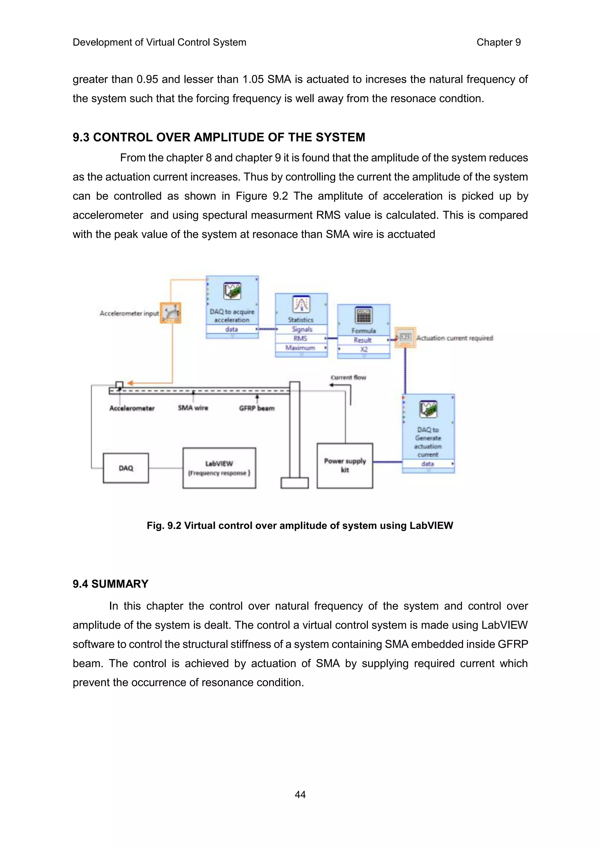
This dissertation explores the characterization of shape memory alloy (SMA) and the development of a virtual control system for monitoring SMA-based smart structures. It emphasizes the importance of identifying the Young's modulus variation of SMA with respect to actuation current, which influences the design of controlled actuators. Experimental results demonstrate significant improvements in frequency shifts and amplitude reductions, highlighting the potential of active monitoring to prevent structural failures.

![Introduction Chapter 1
1
CHAPTER 1
INTRODUCTION
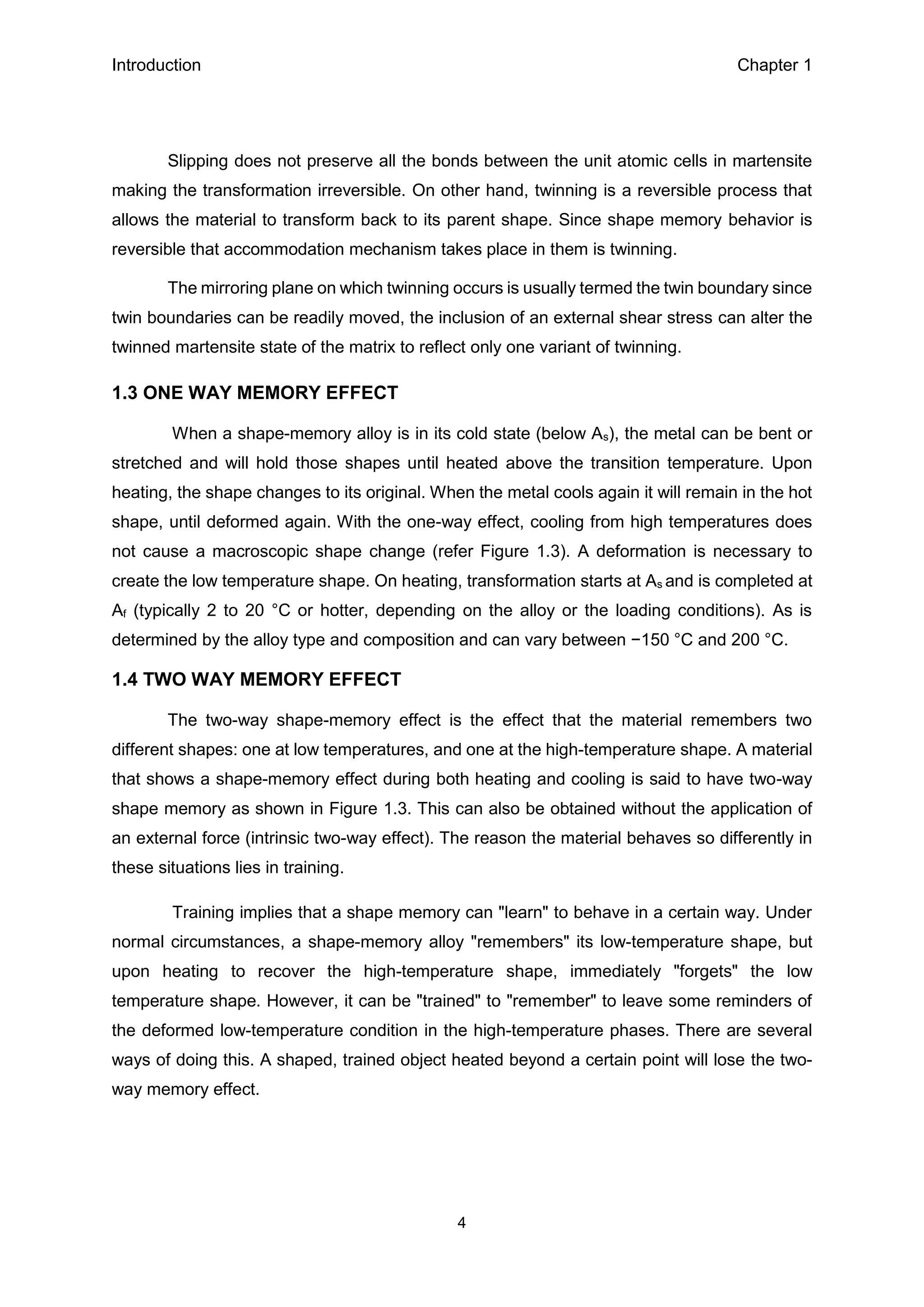
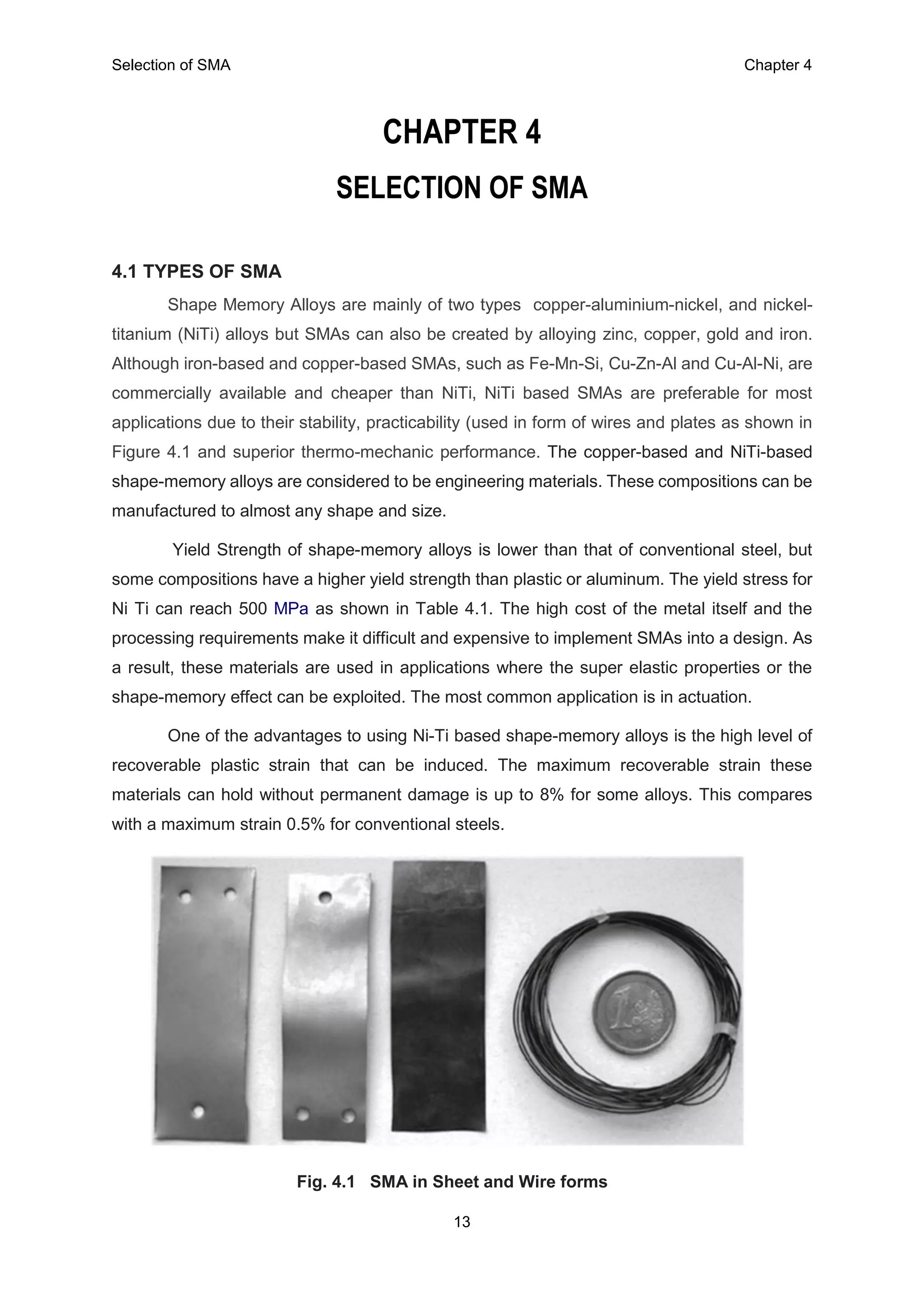
1.1 SHAPE MEMORY ALLOY
Shape memory alloys (SMAs) are family of smart materials. They have the ability to
change their shape depending on their transformation temperatures. SMA, in particular nickel–
titanium alloy (Nitinol), is a metallic alloy that exhibits shape memory effect. When it deforms
at low temperatures, it has the ability to return to its predetermined shape, if heated above its
transformation temperature. The returning to its predetermined shape is the result of
crystalline structure transformation from low temperature martensite (M) phase to high
temperature austenite (A) phase. These two phases have same chemical compositions except
dissimilarity in crystallographic structures. Hence, they show dissimilarities in their thermal,
mechanical and electrical properties [1]. The high-temperature austenitic phase is more rigid
and stronger as compared with low temperature martensite phase. The low-temperature
phase is also known as twinned martensite phase where each layer is separated by a twinning
boundary. This state is highly malleable and has very low elastic limit. When external stress
is applied at this state, the material changes into detwinned variant of martensite phase that
stores generated strain. The strain can be recovered by heating the material at higher
temperatures. During strain recovery, the alloy contracts and exhibits large force against
external resistance [3]. It finally transforms into austenite phase. The thermal hysteresis
represents material transformation characteristic, which provides four distinct transformation
temperatures. Ms and Mf represent the start and finish temperatures of martensite, while As
and Af are the start and finish temperatures of austenite. It changes its status with heating
current. The shape change in the material is observed by its elastic and plastic deformation
as well as thermal expansion and contraction.
a) Mf : Martensite finish, this is the lowest temperature, below all of the material has the
soft martensitic structure
b) Ms : Martensite start, an intermediate temperature, when the martensite phase starts
to appear in the prevalently austenitic phase
c) As : Austenite start, an intermediate temperature, when the austenite phase starts to
appear in the prevalently martensitic phase
d) Af : Austenite finish, this is the highest temperature, above which all of the material has
the hard martensitic structure. Super elastic SMA are designed to work over this
temperature, while the thermal-induced memory effect finishes at this temperature.](https://image.slidesharecdn.com/ilovepdfmerged-180626180915/75/REPORT-ON-CHARACTERIZATION-OF-SHAPE-MEMORY-ALLOY-FOR-VIBRATION-ATTENUATION-IN-SMART-STRUCTURES-12-2048.jpg)
![Introduction Chapter 1
3
Fig. 1.1 Phase transformation in 3D stress strain temperature
When a material changes the phase the rearranging of atoms that takes place is
referred to as transformation as shown in Figure 1.1. In solids there are two known types of
transformation: Displacive and Diffusional In diffusional transformation the rearranging of
atoms occurs across long distances [8]. The new phase formed by diffusional transformation
is of different chemical composition than that of the parent phase. In contrast, a displacive
transformation occurs by the movement of atoms as a unit, with each atom contributing a small
portion of overall displacement. In a displacive transformation the bonds between that atoms
are not broken rather than arranged, thus leaving the parent phase chemical composition
matrix intact. Martensite transformation id shape memory alloys are of displacive type and
transformation takes place between Austenite also usually referred to as the parent phase and
Martensite.
The second step of the martensitic transformation depicts the accommodation process
required as a result of shape change as shown in Figure 1.2. This process of accommodation
is called lattice invariant shear can be accomplished in two ways: Slip and Twinning.
Fig. 1.2 Lattice invariant shear accommodation (b) slip (c) twinning](https://image.slidesharecdn.com/ilovepdfmerged-180626180915/75/REPORT-ON-CHARACTERIZATION-OF-SHAPE-MEMORY-ALLOY-FOR-VIBRATION-ATTENUATION-IN-SMART-STRUCTURES-14-2048.jpg)
![Introduction Chapter 1
6
1.6 APPLICATION OF SHAPE MEMORY ALLOY
Shape memory alloys are a proven smart material with the capability to produce work
over large areas without producing residual strains. This allows the material to span many
depths of applications [7] in areas such as the mechanical, medical and aerospace fields. SMA
materials have been applied to stent operations in the medical field where its hysteretic
behavior fits the stress strain behavior of human bones and tendons while additionally
providing a resistance to radial forces. The minimum energy required for actuation of SMAs
along with the material’s ability to comply with composite materials has allowed it to thrive in
structural connections of space systems. SMAs are a prime candidate to replace bolts and
rivets in this application which can significantly degrade the properties of the structures.
Implementation of SMA materials in beam shaped structures has been confirmed to impact
the vibrational behavior of the structures both numerically and experimentally. The introduction
of the shape memory effect, whereby the shape memory alloy material acts as both a damper
and a means of variable stiffness is a novel technique for high cycle fatigue mitigation. The
impact SMAs have on the vibrational behavior of structures would greatly benefit systems
experiencing harmful flutter vibration.
1.7 Summary
Thus the inherent properties of SMA such as solid phase transformations from low
temperature, low stiffness martensite phase to high temperature, high stiffness austenite
phase, and application of SMA has been dealt in this chapter.](https://image.slidesharecdn.com/ilovepdfmerged-180626180915/75/REPORT-ON-CHARACTERIZATION-OF-SHAPE-MEMORY-ALLOY-FOR-VIBRATION-ATTENUATION-IN-SMART-STRUCTURES-17-2048.jpg)
![Literature review Chapter 2
7
CHAPTER 2
LITERATURE REVIEW
This chapter explains various existing works related applications of SMA and vibration
disturbances in smart structures along with control methodology.
H. N. Bhargaw et al [1] presented the thermo-electric behavior of shape memory alloy
(SMA) wire. When the wire was electrically heated above its transformation temperature by
current, a large mechanical force is exerted due to transformation in its phases. In order to make
use of SMA wire as an actuator, different parameters and their relationships were investigated.
These parameters are recoverable strain (displacement), temperature hysteresis and electrical
resistance variation under different stress levels. Optimum safe heating current was assessed
and phase transformation temperatures were estimated by heat transfer model.
Kin-tak Lau et al [2] presented the development of shape memory alloy (SMA) actuators,
in the forms of wire, thin film and stent have been found and increasingly in the fields of materials
science and smart structures and engineering. The increase in attraction for using these materials
is due to their many unique materials, mechanical, thermal and thermal-mechanical properties,
which in turn, evolve their subsequent shape memory, pseudo-elasticity and super-elasticity
properties. In this paper, a common type of SMA actuator, Nitinol wires, were embedded into
advanced composite structures to modulate the structural dynamic responses, in terms of natural
frequency and damping ratio by using its shape memory and pseudo-elastic properties.
Sia Nemat-Nasser et al [3] showed To characterize the thermomechanical response,
especially the superelastic behavior of NiTi shape-memory alloys (SMAs) at various temperatures
and strain rates, we have performed a series of both quasi-static and dynamic uniaxial
compression tests on cylindrical samples, repeated dynamic tests of the alloy produce smaller
changes in the shape of the superelastic loop and in the dissipated energy than do the quasi-
static cyclic tests; and the superelastic behavior of this material has stronger sensitivity to
temperature than to strain rate; at very high loading rates
Toshibumi Fukuta et al [4] Mechanical properties of shape memory alloy (hereinafter
referred to as SMA) bars were investigated for their structural use of buildings and two examples](https://image.slidesharecdn.com/ilovepdfmerged-180626180915/75/REPORT-ON-CHARACTERIZATION-OF-SHAPE-MEMORY-ALLOY-FOR-VIBRATION-ATTENUATION-IN-SMART-STRUCTURES-18-2048.jpg)
![Literature review Chapter 2
8
of SMA in super elasticity phase applied to structural elements are proposed. The static and
dynamic loading tests on SMA bars demonstrated that the stress strain curve for tensile stress is
completely different from that for compressive stress, irrespective of whether the load is static or
dynamic in nature. Super elasticity was clearly evident under tensile strain of up to around 5%,
but not under compressive strain, due to the presence of residual strain. The yield strength in
compression is almost two times of tension yielding under the strain rate tested.
Gupta. K et al [5] have discussed the use of nitinol [shape memory alloy (SMA)] wires in
the fiber-reinforced composite shaft, for the purpose of modifying shaft stiffness properties to
avoid such failures, is discussed. A setup has been developed to fabricate the composite shaft
(made of fiber glass and epoxy resin) embedded with pre-stressed SMA wires. Experiments have
been carried out on the shaft to estimate the changes in the natural frequency of the composite
shaft due to activation and deactivation of SMA wires. The comparison of the experimental results
with the established analytical results indicates feasibility of vibration control using the special
properties of SMA wires.
Yuvaraja. M et al [6] have presented the significance of shape memory alloy in vibration
control. They have developed a shape memory alloy spring based dynamic vibration absorber
with the help of microcontroller. The vibration was controlled for the range of frequencies from 21
Hz to 27 Hz in case of cantilever beam, which was used as a representation model. They have
demonstrated that multiple SMA springs can be used effectively to control vibration. They have
tested the performance of developed SMA based actively tuned dynamic vibration absorber in
piping application, and found out that the SMA is capable of controlling the amplitude of vibration
for varying excitation frequencies. The vibration in the pipeline was reduced by around 60 % using
SMA based adaptively tuned dynamic vibration absorber.
Jaronie et al [7] describes the attributes of SMAs that make them ideally suited to
actuators in various applications, and addresses their associated limitations to clarify the design
challenges faced by SMA developers. This work provides a timely review of recent SMA research
and commercial applications, with over 100 state-of-the-art patents; which are categorized against
relevant commercial domains and rated according to design objectives of relevance to these
domains (particularly automotive, aerospace, robotic and biomedical). Although this work
presents an extensive review of SMAs, other categories of SMMs are also discussed; including a
historical overview, summary of recent advances and new application opportunities.](https://image.slidesharecdn.com/ilovepdfmerged-180626180915/75/REPORT-ON-CHARACTERIZATION-OF-SHAPE-MEMORY-ALLOY-FOR-VIBRATION-ATTENUATION-IN-SMART-STRUCTURES-19-2048.jpg)
![Literature review Chapter 2
9
Schetky, L.M et al [8] investigates the torsional behavior of Ni-rich Ni50.3Ti29.7Hf20
high-temperature shape memory alloy tubes under pure torsion loading. Torque tubes with
varying geometry including outer diameter, wall thickness, and length were subjected to constant-
torque thermal cycling at stresses ranging from 0–500 MPa (0–175 N-m). It was found that the
wall thickness had a notable effect on the transformation temperatures where thick-walled tubes
transformed at lower temperatures when compared to the thin-walled form.
B.-S. Jung et al [9] investigates SMA wire embedded hybrid composite to have a larger
displacement than a SMA wire embedded single composite. The hybrid composite is designed
with a n-shape and it is comprised of three parts with different stiffness materials, GFRP with
higher stiffness at both ends and silicone rubber with lower stiffness in the middle to increase the
displacement range of the structure. The SMA wire embedded hybrid composite can be actuated
by applying an electric current through the embedded SMA wire. The fabricated composite was
mechanically fastened to prevent separation between the wire and the composite laminae
induced by temperature rise of the wire. The displacement of SMA wire embedded hybrid
composite was examined by measuring the radius of curvature.
Teroko Aoki et al [10] have investigated the characteristics of the damping produced by
the shape recovery force of the smart matrix composite made of epoxy resin with embedded fibers
of Ni-Ti SMA (Shape Memory Alloy) which are tested by vibration experiments using the cantilever
beam method. The characteristics are examined with calculated loss factors obtained by
measuring resonance frequencies and attenuation characteristics. Their study reveals that the
smart matrix composite in this research has characteristics of the damping material by shifting its
resonance frequencies.
Yuvaraja M et al [11] In this paper work Shape memory alloy and piezoelectric based
composites are presented for investigating the vibration characteristics. In former case, GFRP
beam modeled in cantilevered configuration with externally attached SMAs. In later case, GFRP
beam with surface bonded PZT patches are analysed for its vibration characteristics. The
experimental work is carried out for both cases in order to evaluate the vibration control of flexible
beam for first mode, also to find the effectiveness of the proposed actuators and verified
numerically. As a result the vibration characteristic of GFRP beam is more effective when SMA is
used as an actuator.](https://image.slidesharecdn.com/ilovepdfmerged-180626180915/75/REPORT-ON-CHARACTERIZATION-OF-SHAPE-MEMORY-ALLOY-FOR-VIBRATION-ATTENUATION-IN-SMART-STRUCTURES-20-2048.jpg)
![Literature review Chapter 2
10
Irschik, H. et al [12] This paper presents an investigation into design optimization of
actuator patterns for static shape control of composite plates with piezoelectric actuator patches.
An energy optimization based method for finding the optimal control voltages that can actuate a
structure shape close to the desired one within a given error is described. Moreover, a voltage
limitation for each actuator is also imposed to keep its control voltage within a practical range.
Finally, illustrative examples are given to demonstrate the effectiveness of the present equivalent
element and the design optimization scheme. Numerical results show that satisfactory static
shape control can be achieved even after a number of actuators are removed.
Hashemi S.M.T et al [13] has analyzed the dynamical behavior of simply supported and
clamped-free beams and observed the temperature increase causes an increment in stresses of
star and finish of transformation, as well as decrease in hysteresis level and presence of different
elastic modules at austenite and martensite phases, causes a change in system stiffness and
consequently variation in natural frequencies, which leads to an escape from resonance
conditions has been shown clearly.
Gangbing Songa et al [14] have given the design and experiment results of active
position control of shape memory alloy (SMA) wires actuated composite beam. The potential
applications of the experiment included the thermo-distortion compensation for precession space
structure, stem shape control for submarines, and flap shape control for aeronautical applications.
A new control approach including a feed forward action, a PD control action, and a robust
compensator has been developed.
2.1 Literature Outcomes
From the literature survey, vibrational problems in structural applications are one the major
factor to consider and it has a vast scope of development. In order to control this vibration, various
methods of vibration control were studied. Shape memory alloys in the form of actuator wire have
been used for active position control in various application but vibration characteristics of smart
structure containing SMA wire in embedded form is not well established, since the Young’s
modulus change of SMA with respect to actuation current is not explicitly known, there arises a
need to establish an analytical relation between Young’s modulus change and actuation current
which in turn seeks characterization of SMA.](https://image.slidesharecdn.com/ilovepdfmerged-180626180915/75/REPORT-ON-CHARACTERIZATION-OF-SHAPE-MEMORY-ALLOY-FOR-VIBRATION-ATTENUATION-IN-SMART-STRUCTURES-21-2048.jpg)
![Experimentation in UTM Ι Chapter 5
20
Fig. 5.3 Typical Stress Strain diagram of superelastic Nitinol
a) Lower Plateau Strength (LPS)—the stress at 2.5 % strain during unloading of the
sample, after loading to 6 % strain as referred in Figure 5.3.
b) Residual Elongation, Elr[%]—the difference between the strain at a stress of 7.0 MPa
during unloading and the strain at a stress of 7.0 MPa during loading .
c) Uniform Elongation, Elu[%]—the elongation determined at the maximum force
sustained by the test piece just prior to necking, or fracture, or both.
d) Upper Plateau Strength (UPS)—the stress at 3 % strain during loading of the sample.
ZWICK / ROEL 2.5 KN is a German made Universal Testing Machine as shown in Figure
5.4 used of tensile test of the wire specimen.
Fig. 5.4 ZWICK / ROEL 2.5 KN UTM](https://image.slidesharecdn.com/ilovepdfmerged-180626180915/75/REPORT-ON-CHARACTERIZATION-OF-SHAPE-MEMORY-ALLOY-FOR-VIBRATION-ATTENUATION-IN-SMART-STRUCTURES-31-2048.jpg)
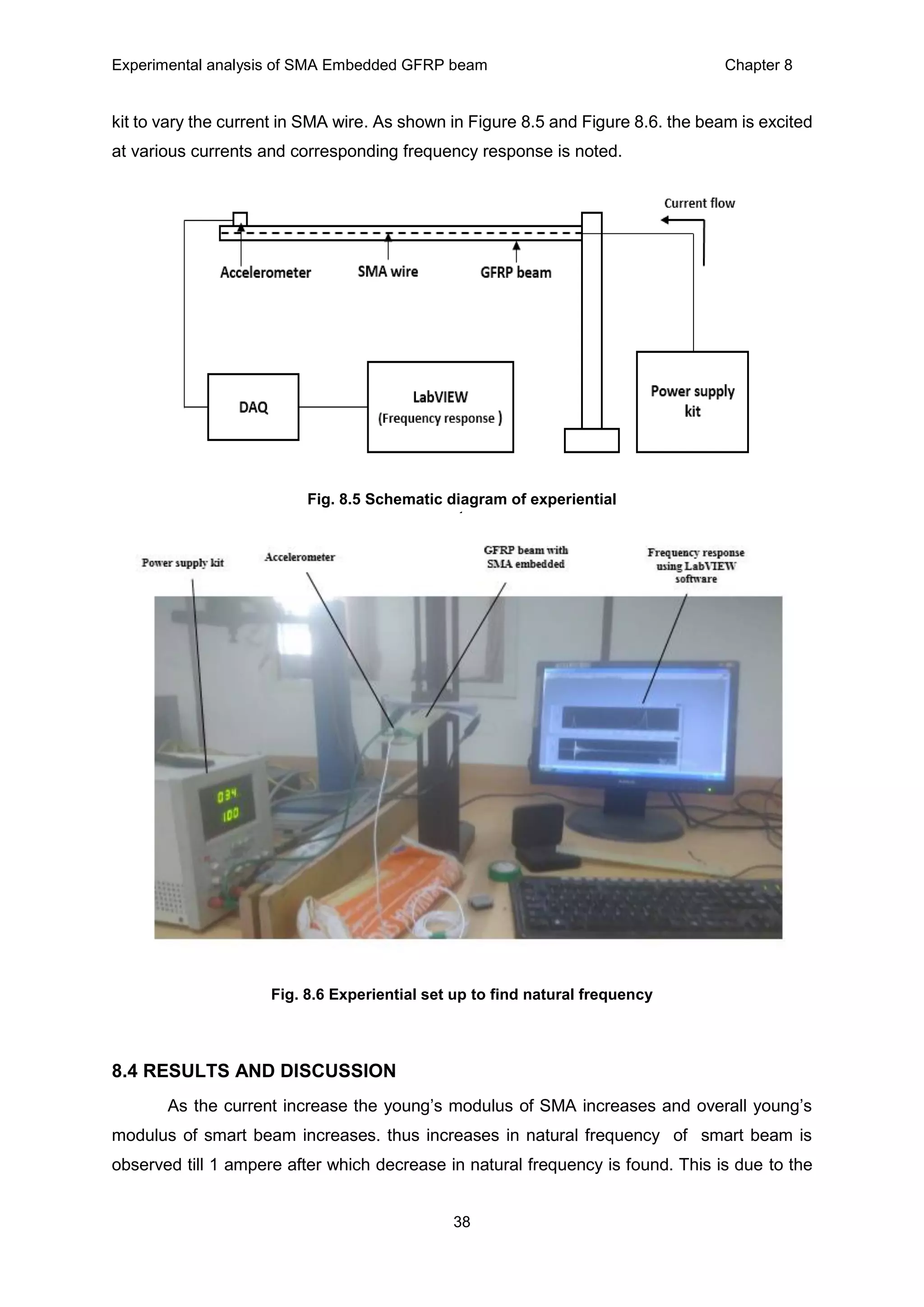
![Experimental analysis of SMA Embedded GFRP beam Chapter 8
39
reason that the overall young’s modulus of smart beam depends on both young’s modulus of
GFRP and young’s modulus of SMA.
From the prior experimental study of SMA in chapter 7 shows that as current increases the
young’s modulus of SMA increases due to its solid phase transformation. Once the current
exceeding 1 ampere the overall temperature of beam increases but young’s modulus of GFRP
decreases with increases in temperature. Thus stiffness of overall beam reduces and
decreases in natural frequency is observed in Figure 8.7.
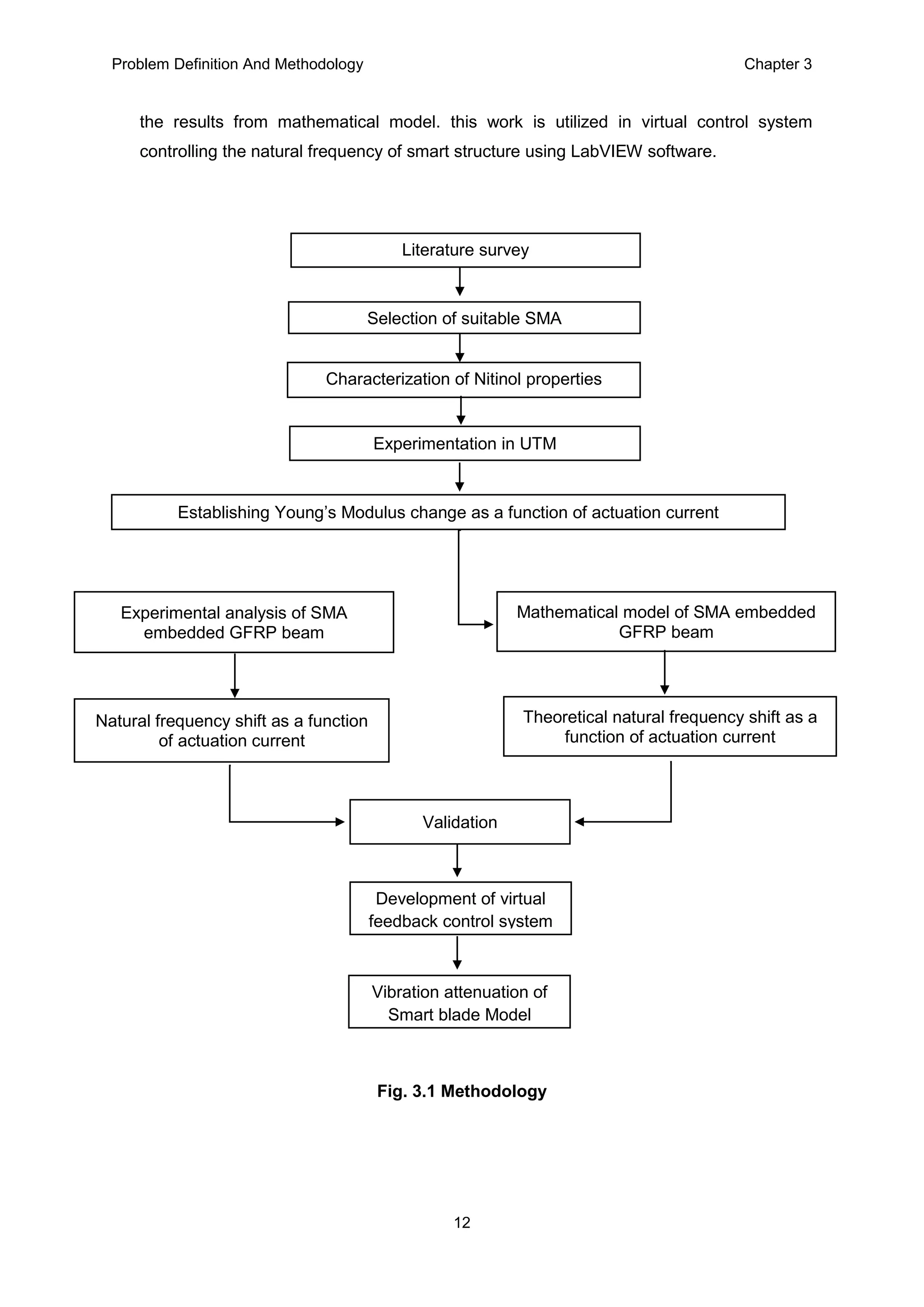
8.6 MATHEMATICAL MODEL OF SMA EMBEDDED GFRP BEAM
In chapter 8 experimental analysis on natural frequency shift of SMA embedded GFRP
beam is presented. A mathematical model is developed to find theoretical natural frequency
shift and it is validated with experimental analysis.
The assumptions made to develop this mathematical model such as the beam is
considered to be cantilever beam subjected to pure bending, and the material properties of
SMA and GFRP is isotropic in nature. For a simple elastic beam problem with uniform
cross section the natural frequency is given by [9],
f(n) =
𝟏
𝟐𝝅
√
𝟑𝑬(𝒄𝒐𝒎𝒃𝒊𝒏𝒆𝒅)𝑰
𝑳 𝟑 𝒎
…………………………………………………………………………………………………………. (2)
Fig. 8.7 Natural frequency of smart beam as a function of current.
155
157
159
161
163
165
167
169
171
173
0 0.5 1 1.5 2 2.5 3
Frequency,Hz
Current, A
Experimental plot](https://image.slidesharecdn.com/ilovepdfmerged-180626180915/75/REPORT-ON-CHARACTERIZATION-OF-SHAPE-MEMORY-ALLOY-FOR-VIBRATION-ATTENUATION-IN-SMART-STRUCTURES-50-2048.jpg)
![Experimental analysis of SMA Embedded GFRP beam Chapter 8
40
The equivalent bending stiffness EI for smart beam with SMA wires, obtained according to the
classical composite-beam theory can be given as [10],
E(combined) = E(GFRP) (1- V(f)) + V(f) E(SMA)………………………………………………………………………....…………………………………….(3)
Where V(f) = volume of SMA / volume of GFRP
Substuting Equation (1) from chapter 7 in (3) the combined Young’s modulas is given as,
E(combined) = E(GFRP) (1- V(f)) + V(f)(-6.7699I2 + 31.077I + 17.738)……………………………………..…… (4)
Young’s Modulus change of GFRP as a function of temperature is shown in [13] is
incorperated as shown equation (5)
E(combined) = E(GFRP)( - 0.013 T(GFRP) + 1.8367) (1- V(f)) + V(f)(-6.7699I2 + 31.077I + 17.738)...................(5)
Where T(GFRP) = 4.9286 I2 – 5.0071 I + 30.964…………………………………………………………….. (6)
f(n) =
𝟏
𝟐𝝅
√
𝟑( − 𝟎.𝟏𝟑 𝑻(𝐺𝐹𝑅𝑃) + 𝟏𝟖.𝟑𝟔𝟕) (𝟏− 𝑽(𝒇)) + 𝑽(𝒇)(−𝟔.𝟕𝟔𝟗𝟗𝑰𝟐 + 𝟑𝟏.𝟎𝟕𝟕𝑰 + 𝟏𝟕.𝟕𝟑𝟖))𝑰𝒎
𝑳 𝟑 𝒎
………..………... (7)
Where, L, m, Im , vf corresponds to length of beam, mass of beam, moment of inertia of
beam, and volume fraction of SMA to GFRP respectively.
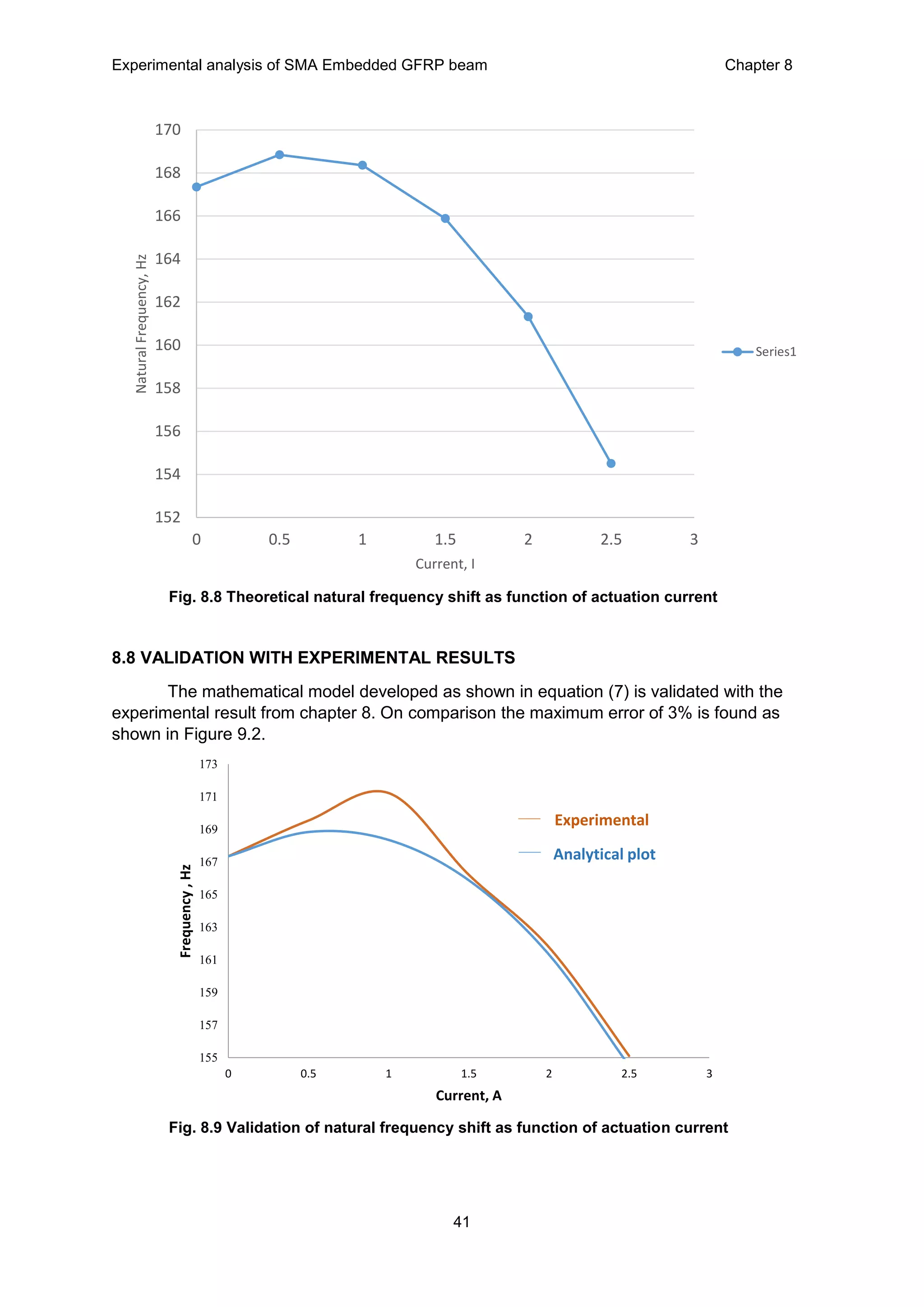
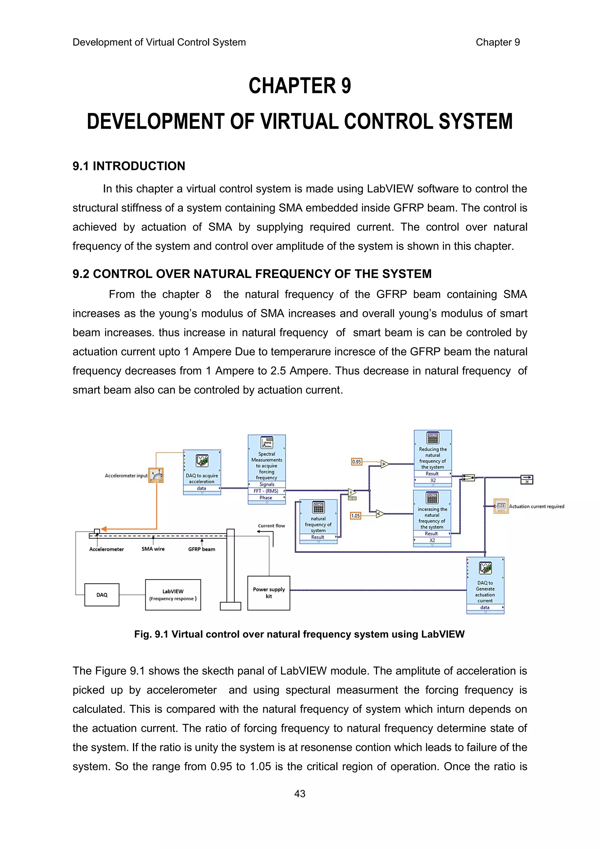
8.7 RESULTS AND DISCUSSION
As the current increase the young’s Modulus of SMA increases and overall young’s
Modulus of smart beam increases. thus increases in natural frequency of smart beam is
observed till 1 ampere after which decrease in natural frequency is found. This is due to the
reason that the overall young’s Modulus of smart beam depends on both young’s Modulus of
GFRP and young’s Modulus of SMA. From the prior experimental study of SMA in chapter 7
shows that as current increases the young’s Modulus of SMA increases due to its solid phase
transformation. Once the current exceeding 1 ampere the overall temperature of beam
increases but young’s Modulus of GFRP decreases with increases in temperature.as shown
in Figure 9.1](https://image.slidesharecdn.com/ilovepdfmerged-180626180915/75/REPORT-ON-CHARACTERIZATION-OF-SHAPE-MEMORY-ALLOY-FOR-VIBRATION-ATTENUATION-IN-SMART-STRUCTURES-51-2048.jpg)
![Bibliography
47
11. Yuvaraja M, Senthilkumar M Procedia Engineering 64 ( 2013 ) 571 – 581,Comparative
study on Vibration Characteristics of a Flexible GFRP Composite beam using SMA
and PZT Actuators
12. Yuvaraja.M and Senthilkumar.M, ”Smart Material(SMA)-Based Actively Tuned
Dynamic Vibration Absorber for Vibration Control in Real Time Application”, Journal of
Engineering and Technology, Vol 3, Issue 2, Jul-Dec 2013.
13. Gangbing Songa, Bthu Kelly, Bnj N. Agrawal, ” Active Position Control of a Shape
Memory Alloy Wire Actuated Composite Beam”, Dept. of Mechanical Engineering, The
university of Akron, Akron, Ohio 44325 b Aeronautics and Astronautics Dept., Naval
Postgraduate School, Monterey, CA 93943.
14. Williams, K., G. Chiu, and R. Bernhard. "Adaptive-passive absorbers using shape-
memory alloys." Journal of Sound and Vibration 249.5 (2002): 835-848.
15. Santos, Filipe Pimentel Amarante dos. "Vibration control with shape-memory alloys in
civil engineering structures." (2011).
16. Esuff Khan and Sivakumar.M.Sirinivasan, “A New Approach to the Design of Helical
Shape Memory Alloy Spring Actuators”, Smart Materials Research Volume 2011,
Article ID 167195, 5 pages.
17. [17]. S.M.T. Hashemi, S.E. Khadem, “Modelling and analysis of the vibration behaviour
of shape memory alloy beam”, I.E.I Communication Industry Co.
18. Trochu F, Qian YY, “Nonlinear finite element simulation of superelastic shape memory
alloy parts”, Comput Struct 1997; 62(5): 799-810.](https://image.slidesharecdn.com/ilovepdfmerged-180626180915/75/REPORT-ON-CHARACTERIZATION-OF-SHAPE-MEMORY-ALLOY-FOR-VIBRATION-ATTENUATION-IN-SMART-STRUCTURES-58-2048.jpg)