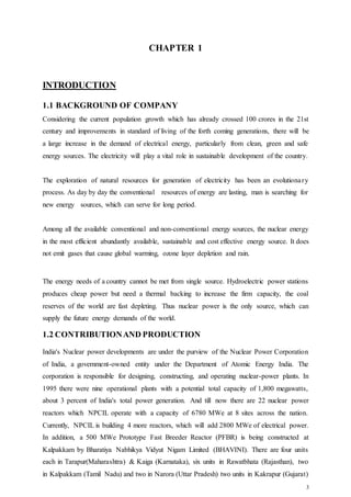
The document is a training report submitted by Rohit Chouhan after completing a 45-day industrial training program at the Nuclear Power Corporation of India Limited (NPCIL) Rajasthan Atomic Power Station. It provides an overview of NPCIL, including its mission to develop nuclear power as a clean and sustainable source of electricity. It describes the layout and key facilities at the Rajasthan Atomic Power Station, and discusses the principles of nuclear fission and power generation. The report aims to document the knowledge gained during the student's training placement.


![40
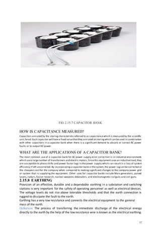
3.2 REFERENCES
[1] www.npcil.nic.in
[2] en.wikipedia.org/wiki/nuclear_power_corporation_of_india.
[3] india.areva.com/…/areva-s-nuclear-epr-projects-in-india-areva-india.html.
[4] Book on “Safety classification of structures, system and components in nuclear power
plants”.
[5] Jain, S.K., Nuclear Power – An alternative (pdf), NPCIL, retrieved 4 March 2012](https://image.slidesharecdn.com/rohitchouhan-190829015150/85/nucliar-power-plant-46-320.jpg)