Download to read offline
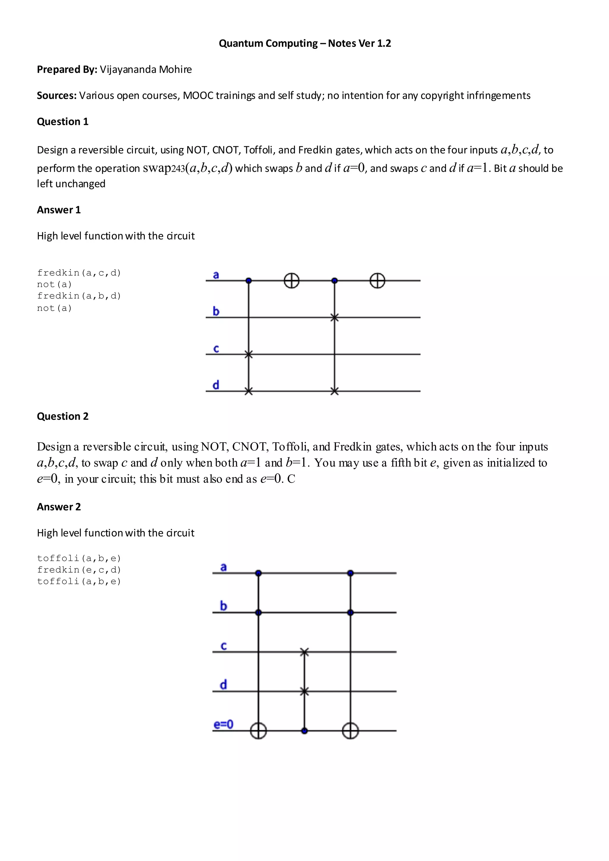
![Question 3
Sample RandomNumber using Q#
Answer 3
open Microsoft.Quantum.Arrays;
open Microsoft.Quantum.Measurement;
operation SampleRandomNumber(nQubits : Int) : Result[] {
// We prepare a register of qubits in a uniform
// superposition state, such that when we measure,
// all bitstrings occur with equal probability.
use register = Qubit[nQubits] {
// Set qubits in superposition.
ApplyToEachA(H, register);
// Measure all qubits and return.
return ForEach(MResetZ, register);
}
}
Question 4
Run a basic quantum circuit expressed using the Qiskit library to an IonQ target via the Azure Quantum
service.
Answer 4
First, import the required packages for this sample:
from qiskit import QuantumCircuit
from qiskit.visualization import plot_histogram
from qiskit.tools.monitor import job_monitor
from azure.quantum.qiskit import AzureQuantumProvider
#Connect to backend Azure quantum service, using below function
from azure.quantum.qiskit import AzureQuantumProvider
provider = AzureQuantumProvider ( resource_id = " ", location = " " )
# Create a Quantum Circuit acting on the q register
circuit = QuantumCircuit(3, 3)
circuit.name = "Qiskit Sample - 3-qubit GHZ circuit"
circuit.h(0)
circuit.cx(0, 1)
circuit.cx(1, 2)
circuit.measure([0,1,2], [0, 1, 2])
# Print out the circuit
circuit.draw()
┌───┐ ┌─┐
q_0: ┤ H ├──■───────┤M├──────
└───┘┌─┴─┐ └╥┘┌─┐
q_1: ─────┤ X ├──■───╫─┤M├───
└───┘┌─┴─┐ ║ └╥┘┌─┐
q_2: ──────────┤ X ├─╫──╫─┤M├
└───┘ ║ ║ └╥┘
c: 3/════════════════╩══╩══╩═
0 1 2](https://image.slidesharecdn.com/quantumcomputingnotesver1-220802114732-60697743/75/Quantum-Computing-Notes-Ver-1-2-2-2048.jpg)
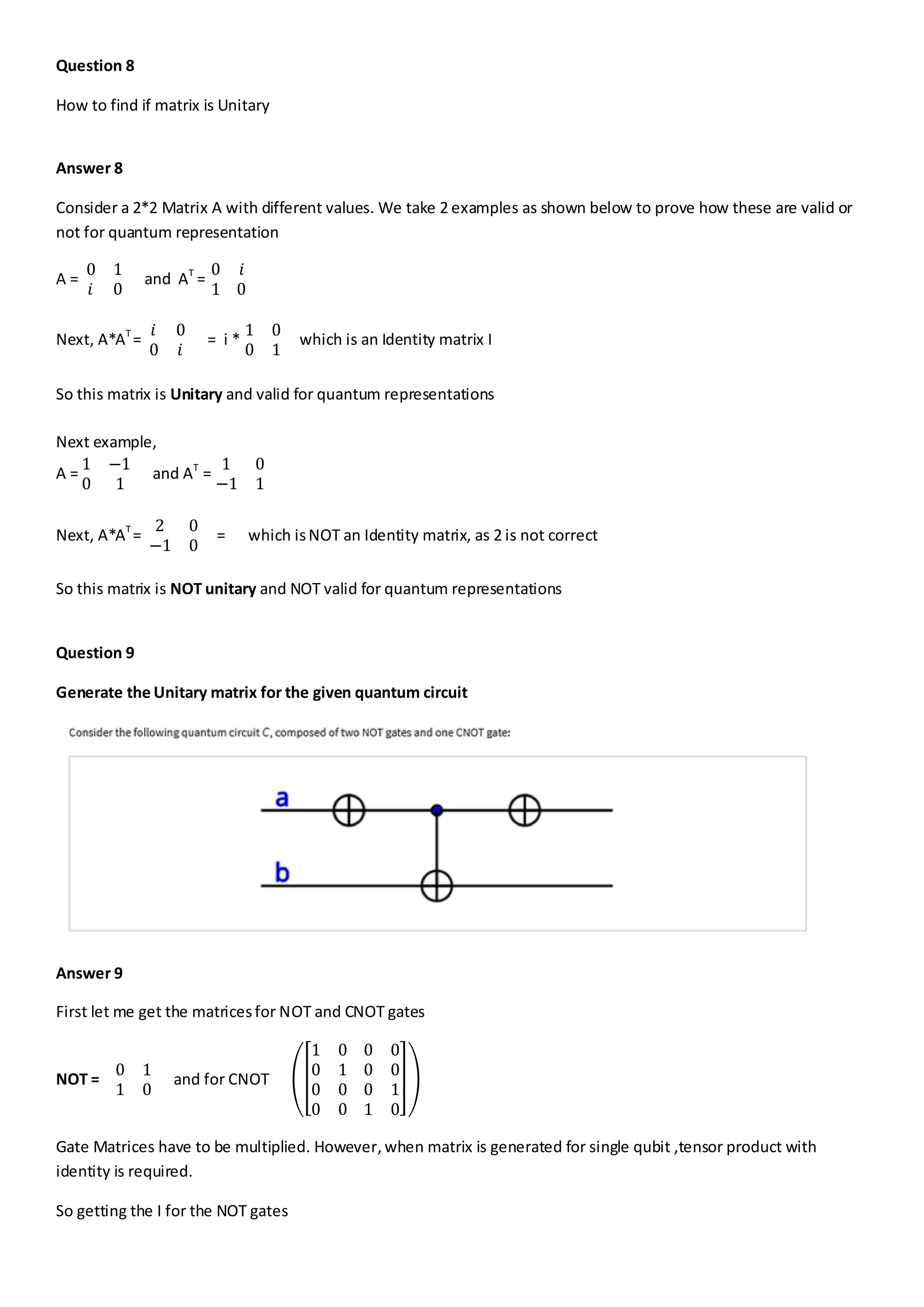
![#Create a Backend object to connect to the IonQ Simulator back-end:
simulator_backend = provider.get_backend("ionq.simulator")
job = simulator_backend.run(circuit, shots=100)
job_id = job.id()
print("Job id", job_id)
#Create a job monitor object
job_monitor(job)
#To wait until the job is completed and return the results, run:
result = job.result()
qiskit.result.result.Result
print(result)
connect to real hardware (Quantum Processing Unit or QPU)
qpu_backend = provider.get_backend("ionq.qpu")
# Submit the circuit to run on Azure Quantum
qpu_job = qpu_backend.run(circuit, shots=1024)
job_id = qpu_job.id()
print("Job id", job_id)
# Monitor job progress and wait until complete:
job_monitor(qpu_job)
# Get the job results (this method also waits for the Job to complete):
result = qpu_job.result()
print(result)
counts = {format(n, "03b"): 0 for n in range(8)}
counts.update(result.get_counts(circuit))
print(counts)
plot_histogram(counts)
Question 5
Develop Google AI sample Cirq circuit
Answer 5
import cirq
qubits = [cirq.GridQubit(x, y) for x in range(3) for y in range(3)]
print(qubits[0])
# This is an Pauli X gate. It is an object instance.
x_gate = cirq.X
# Applying it to the qubit at location (0, 0) (defined above)
# turns it into an operation.
x_op = x_gate(qubits[0])
print(x_op)
cz = cirq.CZ(qubits[0], qubits[1])
x = cirq.X(qubits[2])
moment = cirq.Moment([x, cz])
x2 = cirq.X(qubits[2])
cz12 = cirq.CZ(qubits[1], qubits[2])
moment0 = cirq.Moment([cz01, x2])](https://image.slidesharecdn.com/quantumcomputingnotesver1-220802114732-60697743/75/Quantum-Computing-Notes-Ver-1-2-3-2048.jpg)
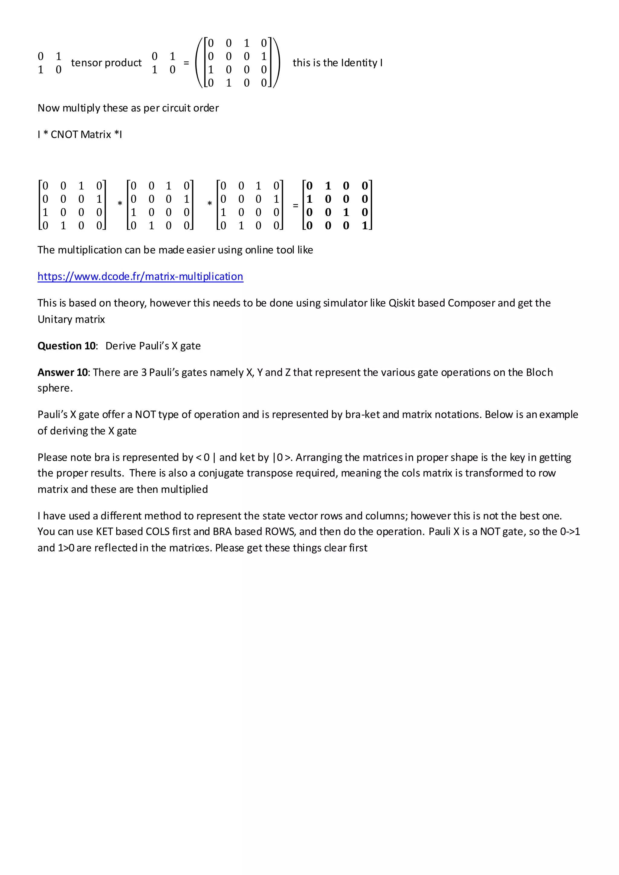
![moment1 = cirq.Moment([cz12])
circuit = cirq.Circuit((moment0, moment1))
print(circuit)
Question 6
Design a simple Tensorflow based quantum Colab sample
Answer 6
!pip install tensorflow==2.4.1
!pip install tensorflow-quantum
import tensorflow as tf
import tensorflow_quantum as tfq
import cirq
import sympy
import numpy as np
# visualization tools
%matplotlib inline
import matplotlib.pyplot as plt
from cirq.contrib.svg import SVGCircuit
a, b = sympy.symbols('a b')
# Create two qubits
q0, q1 = cirq.GridQubit.rect(1, 2)
# Create a circuit on these qubits using the parameters you created above.
circuit = cirq.Circuit(
cirq.rx(a).on(q0),
cirq.ry(b).on(q1), cirq.CNOT(control=q0, target=q1))
SVGCircuit(circuit)
# Calculate a state vector with a=0.5 and b=-0.5.
resolver = cirq.ParamResolver({a: 0.5, b: -0.5})
output_state_vector = cirq.Simulator().simulate(circuit, resolver).final_state_vector
output_state_vector](https://image.slidesharecdn.com/quantumcomputingnotesver1-220802114732-60697743/75/Quantum-Computing-Notes-Ver-1-2-4-2048.jpg)
![Question 7
Design a simple qubit based quantum circuit using IBMQiskit
Answer 7
import numpy as np
# Importing standard Qiskit libraries
from qiskit import QuantumCircuit, transpile, Aer, IBMQ, assemble
from qiskit.tools.jupyter import *
from qiskit.visualization import *
from ibm_quantum_widgets import *
from math import pi, sqrt
# Loading your IBM Quantum account(s)
provider = IBMQ.load_account()
sim = Aer.get_backend('aer_simulator')
# Let's do an X-gate on a |0> qubit
qc = QuantumCircuit(1)
qc.x(0)
qc.draw()
qc.y(0) # Do Y-gate on qubit 0
qc.z(0) # Do Z-gate on qubit 0
qc.draw()
# Create the X-measurement function:
def x_measurement(qc, qubit, cbit):
"""Measure 'qubit' in the X-basis, and store the result in 'cbit'"""
qc.h(qubit)
qc.measure(qubit, cbit)
return qc
initial_state = [1/sqrt(2), -1/sqrt(2)]
# Initialize our qubit and measure it
qc = QuantumCircuit(1,1)
qc.initialize(initial_state, 0)
x_measurement(qc, 0, 0) # measure qubit 0 to classical bit 0
qc.draw()](https://image.slidesharecdn.com/quantumcomputingnotesver1-220802114732-60697743/75/Quantum-Computing-Notes-Ver-1-2-5-2048.jpg)
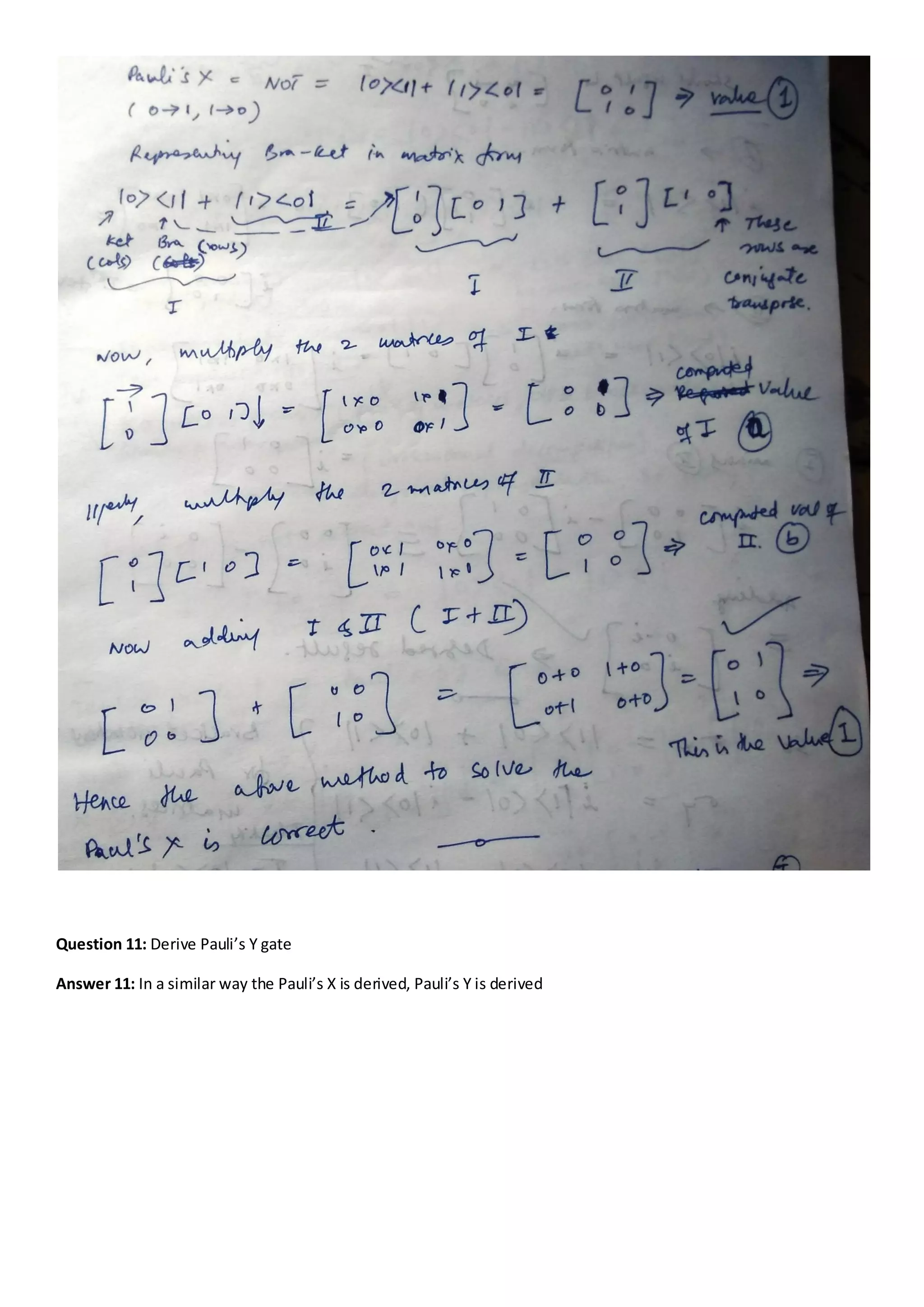
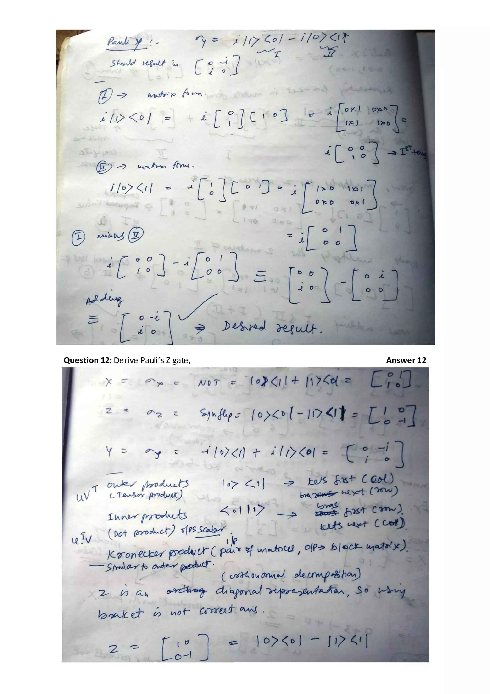
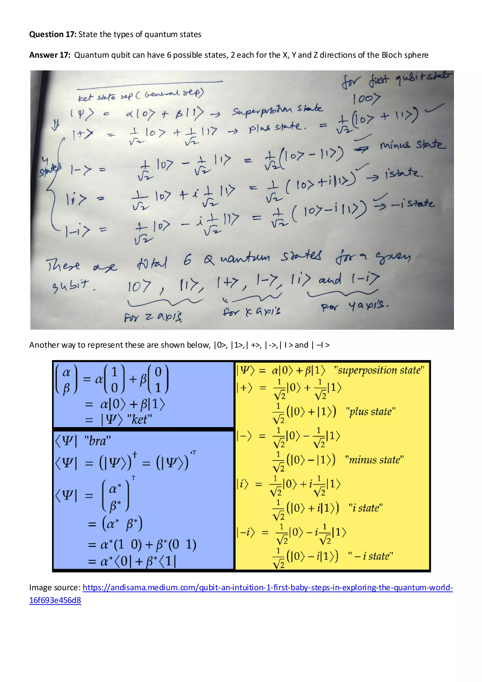
![Question 18: Define the notations for the different types of quantum states like plus, minus etc
Answer 18: Quantum qubit state notations are mainly represented in matrix and bra-ket forms with transformation
from one notation to another as required to solve a problem .Below are matrix notations for 0,1, + and – states.
These can be re-written from matrix to state, like col matrix [1 0] can be written as ket notation | 0> as per the need
of the problem to be solved
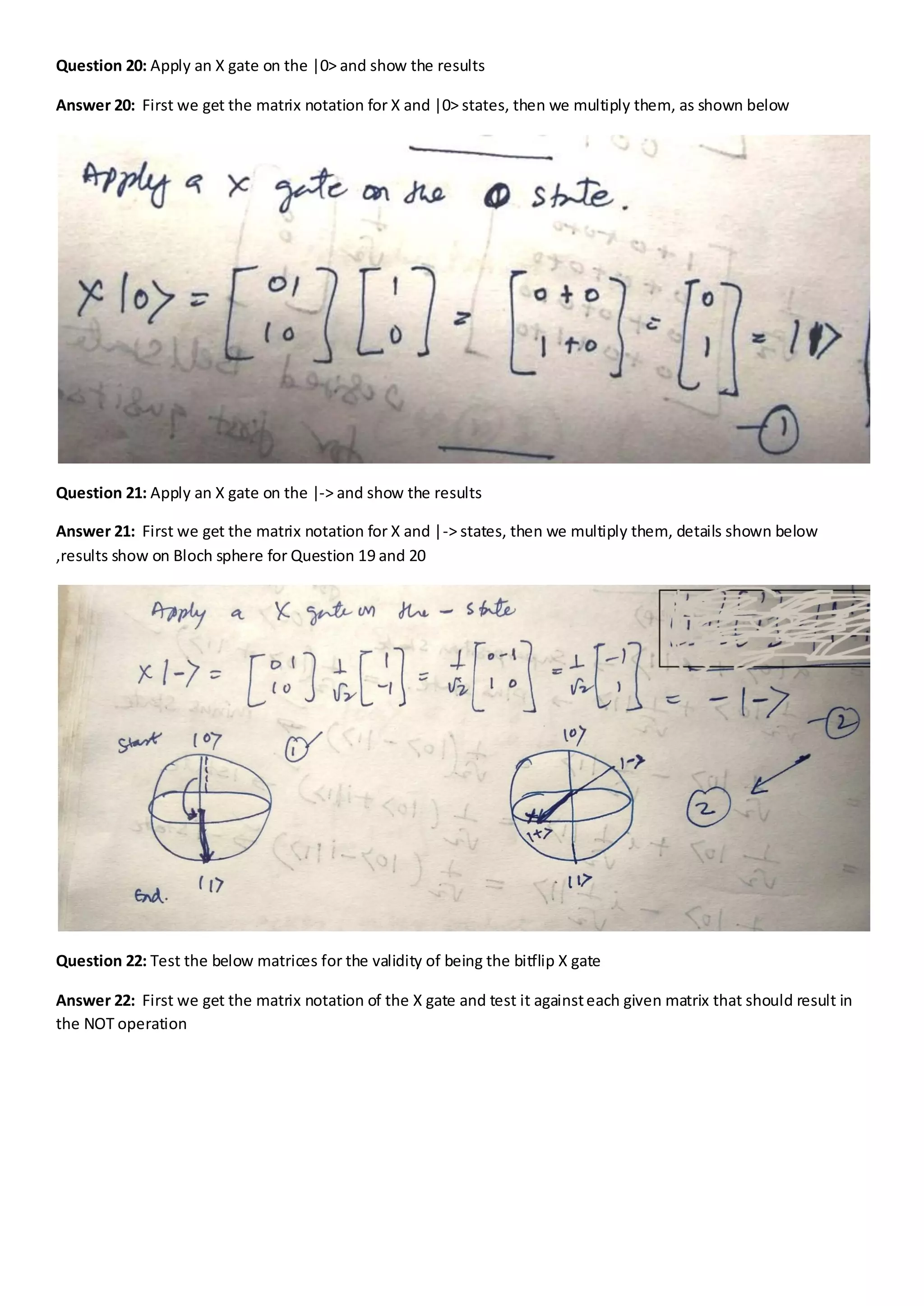
Question 19: Apply an H gate on the |+> and show the results
Answer 19: First we get the matrix notation for H and |+> states, then we multiply them, details shown below](https://image.slidesharecdn.com/quantumcomputingnotesver1-220802114732-60697743/75/Quantum-Computing-Notes-Ver-1-2-14-2048.jpg)
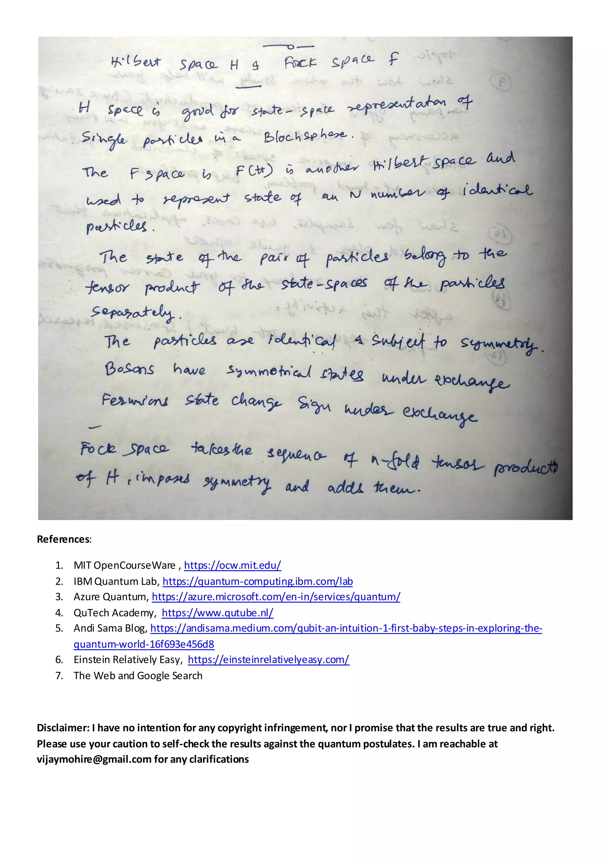

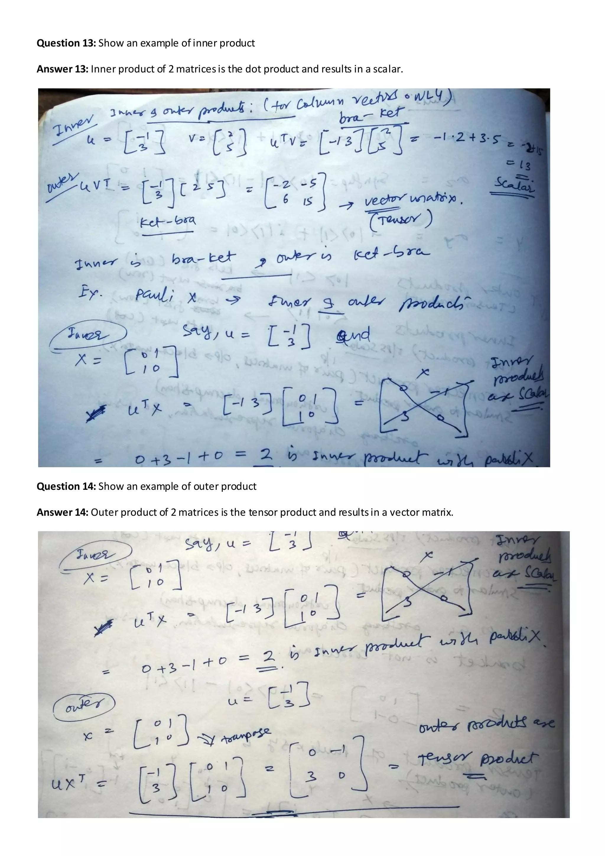
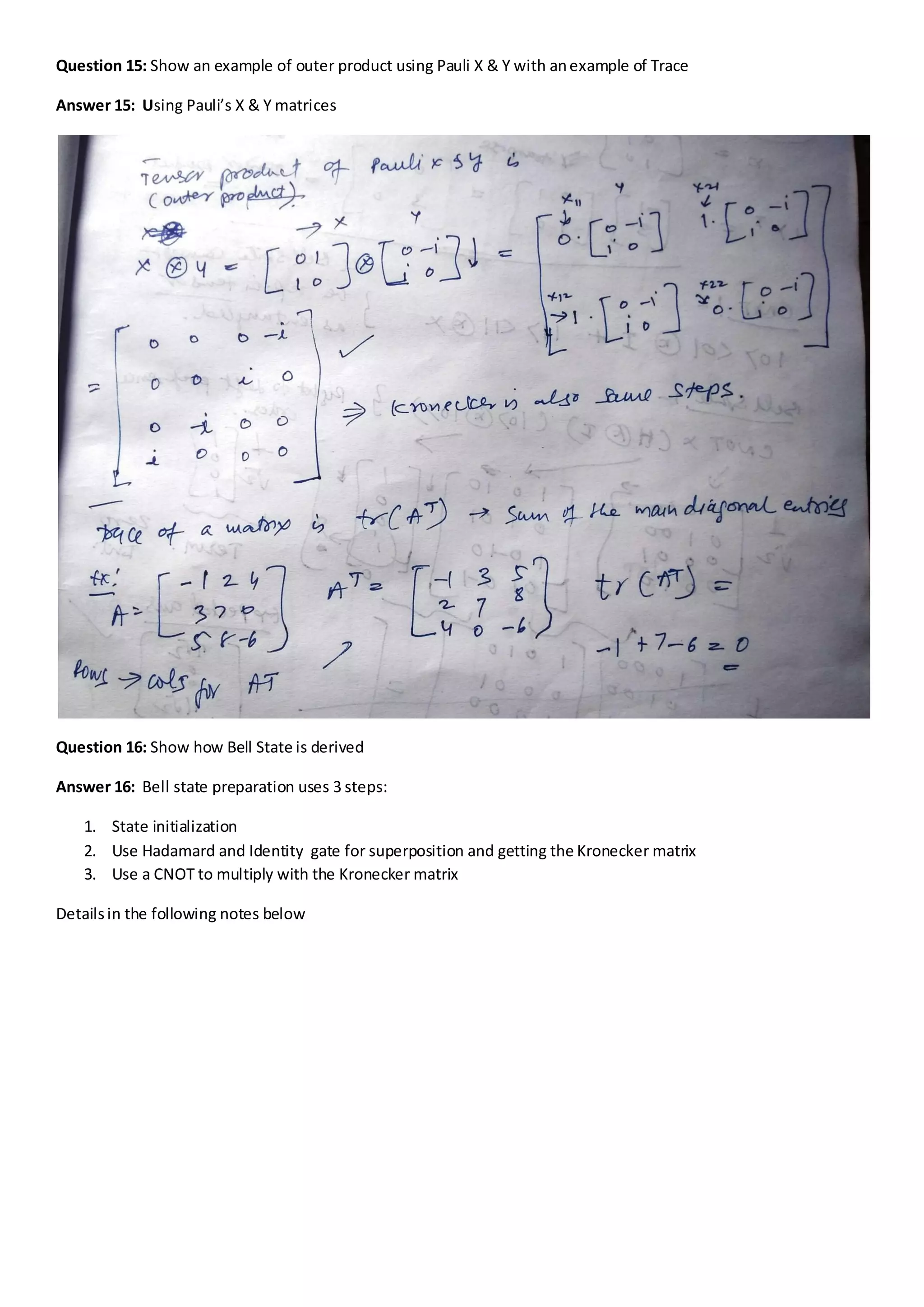
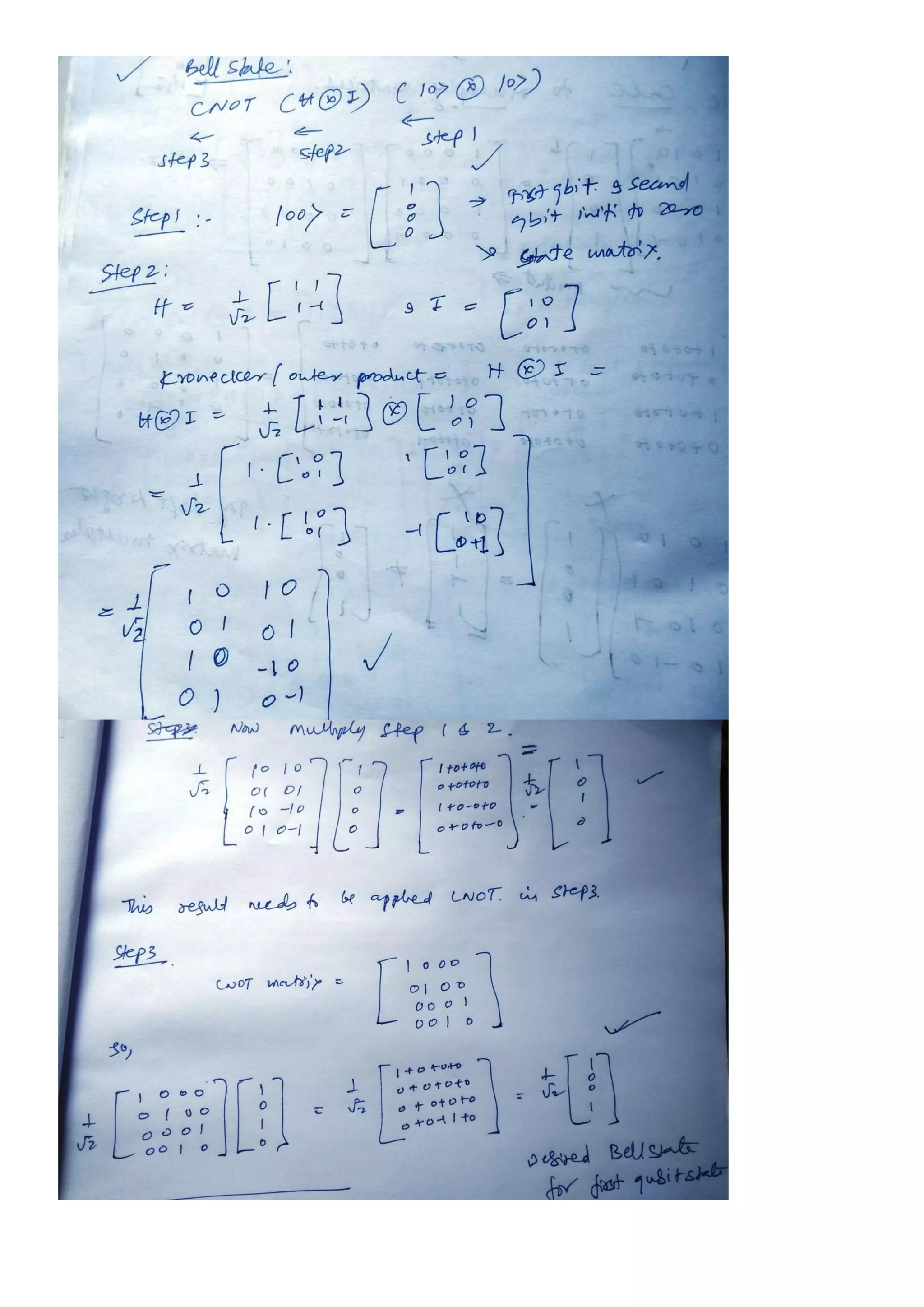
The document contains various quantum computing concepts, including questions and answers on designing reversible circuits, generating random numbers, running quantum circuits with Qiskit and Cirq, and deriving quantum gates such as Pauli's X, Y, and Z. It also discusses the representation of quantum states, unitary matrices, and Fock space as a method for representing multi-particles. The document includes references to educational resources and emphasizes self-verification of results against quantum principles.