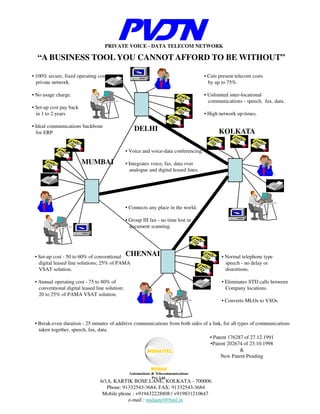
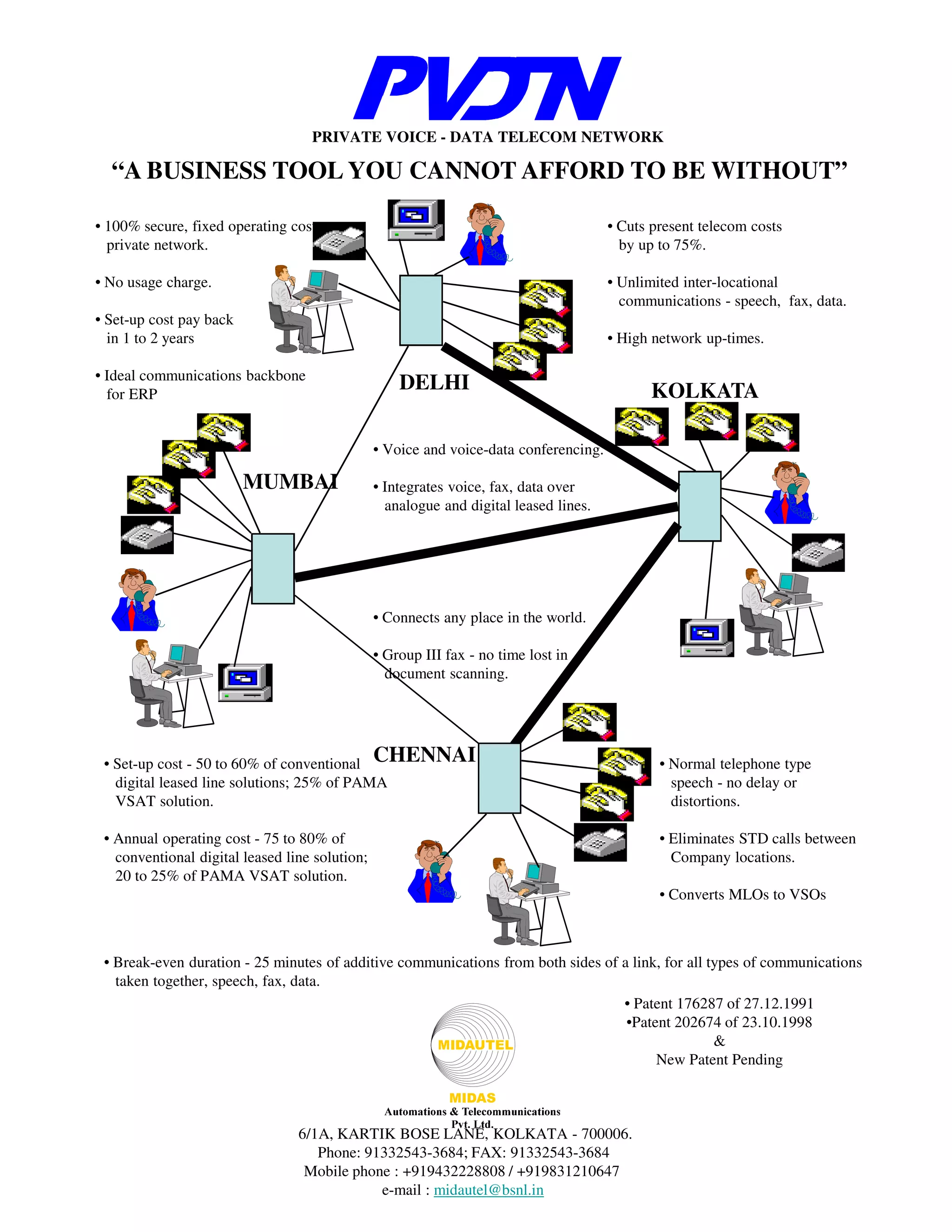
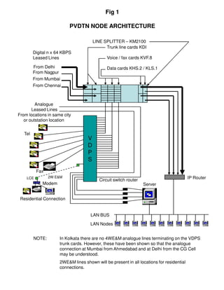
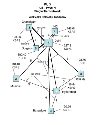
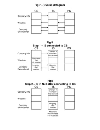
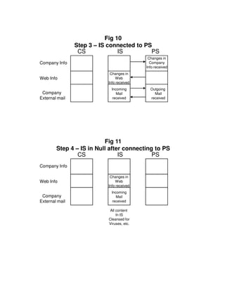
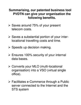
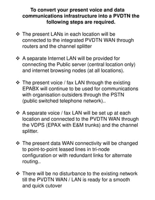
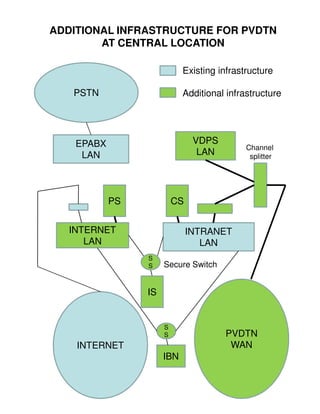
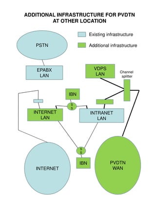
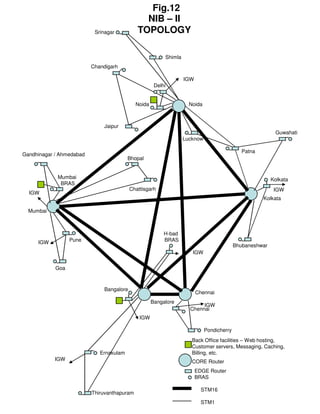
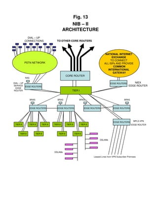
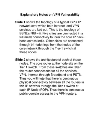
PRIVATE VOICE - DATA TELECOM NETWORK

  “A BUSINESS TOOL YOU CANNOT AFFORD TO BE WITHOUT”

• 100% secure, fixed operating cost,                                                   • Cuts present telecom costs
  private network.                                                                       by up to 75%.

• No usage charge.                                                                     • Unlimited inter-locational
                                                                                         communications - speech, fax, data.
• Set-up cost pay back
  in 1 to 2 years                                                                      • High network up-times.

• Ideal communications backbone
  for ERP
                                                    DELHI                                    KOLKATA

                                                • Voice and voice-data conferencing.

                         MUMBAI                 • Integrates voice, fax, data over
                                                  analogue and digital leased lines.


                                                • Connects any place in the world.

                                                • Group III fax - no time lost in
                                                  document scanning.


 • Set-up cost - 50 to 60% of conventional CHENNAI                                             • Normal telephone type
   digital leased line solutions; 25% of PAMA                                                    speech - no delay or
   VSAT solution.                                                                                distortions.

 • Annual operating cost - 75 to 80% of                                                        • Eliminates STD calls between
   conventional digital leased line solution;                                                    Company locations.
   20 to 25% of PAMA VSAT solution.
                                                                                               • Converts MLOs to VSOs


 • Break-even duration - 25 minutes of additive communications from both sides of a link, for all types of communications
   taken together, speech, fax, data.
                                                                                  • Patent 176287 of 27.12.1991
                                                                                   •Patent 202674 of 23.10.1998
                                                                                                   &
                                                                                        New Patent Pending


                                 6/1A, KARTIK BOSE LANE, KOLKATA - 700006.
                                    Phone: 91332543-3684; FAX: 91332543-3684
                                  Mobile phone : +919432228808 / +919831210647
                                             e-mail : midautel@bsnl.in
Fig 1

                           PVDTN NODE ARCHITECTURE

                                        LINE SPLITTER – KM2100
                                              Trunk line cards KDI
         Digital n x 64 KBPS
         Leased Lines                          Voice / fax cards KVF.8

         From Delhi                            Data cards KHS.2 / KLS.1
         From Nagpur
         From Mumbai
         From Chennai


         Analogue
       Leased Lines
From locations in same city
   or outstation location


   Tel
                                    V
                                    D
                                    P
                                    S
          Fax
    LCE          2W E&M                                                                    IP Router
                                           Circuit switch router
             Modem                                                 Server


 Residential Connection


                                      LAN BUS

                                      LAN Nodes


         NOTE:        In Kolkata there are no 4WE&M analogue lines terminating on the VDPS
                      trunk cards. However, these have been shown so that the analogue
                      connection at Mumbai from Ahmedabad and at Delhi from the CG Cell
                      may be understood.
                      2WE&M lines shown will be present in all locations for residential
                      connections.
Fig 2
                       TYPICAL STATE WAN CONFIG
                        USING MULTI-TIER PVDTN
            FOR INTEGRATED VOICE, FAX, DATA COMMUNICATIONS
                        UP TO GRAM PANCHAYAT
              WITH 100% ALTERNATE ROUTING / REDUNDANCY
                                                                                                                    6.22 KBPS
                                           62.42 KBPS                           2       2       2

                                                                                                                            1       1       1       1
                               2 X 128 KBPS                                                             2
                                                                                                                                                    1

         320.7 KBPS                                                                                     2                                           1
                                   3
                                                                    3                                                                               1
                           3                   3            3           3
                                                                                                2 X 2WE&M                               1
                                                                                                                                                1
                                                       6        6
                                           6
            384 KBPS                                                        6
                                                                                            4                       4
                           3           6                                                                                                4
                                                                                                                            4
                               3                                                4
                                   768 KBPS                                                     8
                                                                4
                           3
                                                                        8
                                                   4        8
                                                                                                                8                               4
                                       4                                                                                    8
                                             2 MBPS
                                                                                                                                                4
        1958.6 KBPS                        8     4 MBPS
                                   4                                                                                            8
                                                                                                                                                4
                                           8                                                KOLKATA
                                                                                                                                8
                   4                           8
                      4
                                                                                                                                8               4
                                           8
                  4
                                                                                                                            8               4
                                                                                                                8
                                                                    8
                                                                                    8               8
                      4                    8           4 MBPS
                                                                                                                                        4

             2 MBPS 4
                                                                                                                        4
                                                                        4                                                           4
                          4                                 4                           4                   4


NOTE : Total number of trunks emanating from Kolkata is 144 (8 x 18). Using the Erlang loading
norm this can serve 1152 extensions in Kolkata. Thus 1158 officers may be provided NET
telephones and they may be spread across Writers’ Building, New Secretariat, and the Secretariats
at Salt Lake
Fig 3
                           CII – PVDTN
                        Single Tier Network

                WIDE AREA NETWORK TOPOLOGY

          Chandigarh

                3            512 KBPS             IHC
                                                                140.64
                                                  4              KBPS
                                  9       4               192 KBPS
 120.96
 KBPS                    6                         Delhi
         320 KBPS                         7
                                                             227.2
          Gurgaon 6               9
                                                             KBPS

       300.40
        KBPS                                                    6
                    5                                                    103.76
                             256 KBPS
118.48                                                                   KBPS
KBPS
                                                   6
                    128 KBPS                                                3
   2                                                                     Kolkata
                                                            3
                3                                             110.64
Mumbai
                                                              KBPS
                                                      3    Hyderabad
                                      6
                                                      3

                                                           120.96
                        Bangalore             3            KBPS
Fig 4
           TRI-
           TRI-NODE FORMATION
                 IN PVDTN
 USED FOR SINGLE AND MULTI-TIER NETWORKS
                       MULTI-
             X
                                 MAX (X,Y)                       Y
                  A

                                                         B


                      X+Y
                                               X+Y


                                 C

1.   X and Y are the total bandwidth impinged on the WAN at each location
     at A and B respectively. This includes bandwidth for data, speech, and
     fax communications.
2.   The derivation of X and Y at each location is shown in Table I of our
     draft proposal presentation.
3.   The link bandwidth calculations are shown in Table II of draft proposal
     presentation. As shown above the main links AC and BC will have a
     total bandwidth of X + Y. This is to take care of 100% alternate routing
     in case of failure of either AC or BC links.
4.   The cross link AB will have the larger of the two bandwidths X,Y.
5.   We hope this will help you to understand the basis of derivation of
     location and link bandwidths shown in our draft proposal presentation.
Fig 5
                 Schematic Diagram of STS

                                      Storage


                   INTERNET              PS


                       STS               IS


                   INTRANET              CS


•PS, IS, CS have same fields which are synchronised at each
connection.
•CS collates data from internal data bases to pass on to PS
through IS, and also distributes information received from the
interactive Web pages in the PS to the relevant data base.
•The information stored in the Storage associated with the PS
helps to carry out e-commerce activity like placing orders, internet
banking. Etc. The storage is updated in each STS cycle.
Fig 6

                     Switching arrangement of
                               STS


                                                           Public Server
                            Company                  For Company information,
 Company                   information                Inter-active Web pages
 data bases                    and                               and
                           mail server                 Internet mail Gateway
DB1        DB2                 CS                                 PS


       Company LAN                           0                     Internet LAN
                                         1       2

                                                     3-Pos Electro-mechanical
                                                           RJ45 switch


                                   Intermediate Server
                               For transferring information
                                  and mail back and forth
                                   Between CS and PS
                                            (IS)
                                 Switch changes state on
 CL                   IL      Automated settable commands
 I/O                 I/O            from software in IS
 Box                 Box


           0
       1       2
                      3-Pos EM RJ45
                           Switch
                       State changes
                   With manual command
                         From Node
     Nodes for
 Internet browsing
Fig 7 – Overall datagram

                   CS                 IS          PS
Company Info


Web Info


 Company
External mail


                             Fig 8
                 Step 1 – IS connected to CS
                  CS              IS        PS
                                  Changes in
Company Info                       Company
                                 Info received
                 Changes in
Web Info            Web
                Info received
                 Incoming         Outgoing
 Company            Mail            Mail
External mail     received        received


                            Fig9
        Step 2 – IS in Null after connecting to CS
                CS              IS          PS
                                  Changes in
Company Info                       Company
                                 Info received


Web Info

                                  Outgoing
 Company                            Mail
External mail                     received

                                  All content
                                In IS cleansed
                                For viruses etc
Fig 10
                Step 3 – IS connected to PS
                 CS             IS         PS
                                            Changes in
Company Info                                 Company
                                           Info received
                            Changes in
Web Info                       Web
                           Info received
                            Incoming         Outgoing
 Company                       Mail            Mail
External mail                received        received


                          Fig 11
        Step 4 – IS in Null after connecting to PS
                CS              IS          PS
Company Info

                            Changes in
Web Info                       Web
                           Info received
                            Incoming
 Company                       Mail
External mail                received

                            All content
                                In IS
                           Cleansed for
                           Viruses, etc.
Summarising, our patented business tool
  PVDTN can give your organisation the
          following benefits.

 Saves around 75% of your present
 telecom costs.

 Saves a substantial portion of your inter-
 locational travelling costs and time.

 Speeds up decision making.

 Ensures 100% security of your internal
 data bases.

 Converts your MLO (multi-locational
 organisation) into a VSO (virtual single
 office).

 Facilitates e-Commerce through a Public
 server connected to the Internet and the
 STS system
To convert your present voice and data
communications infrastructure into a PVDTN the
        following steps are required.

The present LANs in each location will be
connected to the integrated PVDTN WAN through
routers and the channel splitter

A separate Internet LAN will be provided for
connecting the Public server (central location only)
and internet browsing nodes (at all locations).

The present voice / fax LAN through the existing
EPABX will continue to be used for communications
with organisation outsiders through the PSTN
(public switched telephone network)..

A separate voice / fax LAN will be set up at each
location and connected to the PVDTN WAN through
the VDPS (EPAX with E&M trunks) and the channel
splitter.

The present data WAN connectivity will be changed
to point-to-point leased lines in tri-node
configuration or with redundant links for alternate
routing..

There will be no disturbance to the existing network
till the PVDTN WAN / LAN is ready for a smooth
and quick cutover
ADDITIONAL INFRASTRUCTURE FOR PVDTN
        AT CENTRAL LOCATION

                            Existing infrastructure

   PSTN                     Additional infrastructure


    EPABX                       VDPS
                                            Channel
     LAN                         LAN         splitter


            PS            CS


  INTERNET                     INTRANET
     LAN                          LAN
                 S
                 S    Secure Switch


                 IS


                      S
                      S                PVDTN
    INTERNET                            WAN
                      IBN
ADDITIONAL INFRASTRUCTURE FOR PVDTN
         AT OTHER LOCATION

                          Existing infrastructure

   PSTN                   Additional infrastructure


    EPABX                   VDPS
                                          Channel
     LAN                     LAN           splitter


              IBN

              S
              S
  INTERNET                INTRANET
     LAN                     LAN


                    S
                    S


                    IBN             PVDTN
   INTERNET                          WAN
Fig.12
                                               NIB – II
                           Srinagar          TOPOLOGY

                                                          Shimla
                          Chandigarh

                                                                   IGW
                                                      Delhi


                                             Noida                   Noida


                              Jaipur
                                                                                                           Guwahati
                                                                   Lucknow

                                                                                              Patna
Gandhinagar / Ahmedabad
                                         Bhopal


             Mumbai                                                                                       Kolkata
              BRAS
                                          Chattisgarh                                                      IGW
  IGW
                                                                                                      Kolkata

  Mumbai


                                                          H-bad
     IGW          Pune                                    BRAS
                                                                                           Bhubaneshwar
                                                                      IGW


            Goa


                              Bangalore
                                                                         Chennai
                                                     Bangalore
                                                                          IGW
                                                                     Chennai
                                              IGW

                                                                             Pondicherry
                                                                      Back Office facilities – Web hosting,
                                                                      Customer servers, Messaging, Caching,
                             Ernakulam                                Billing, etc.
           IGW                                                        CORE Router
                                                                         EDGE Router
                                                                         BRAS

                                                                           STM16
                          Thiruvanthapuram
                                                                           STM1
Fig. 13
                                                     NIB – II
                                                  ARCHITECTURE
             DIAL – UP
           CONNECTIONS                     TO OTHER CORE ROUTERS


                                                                                             NATIONAL INTERNET
                                                                                                  EXCHANGE
                                                                                                 TO CONNECT
           PSTN NETWORK                                                                     ALL ISPs AND PROVIDE
                                                                                                   COMMON
                                                                                               INTERNATIONAL
                                                                                                   GATEWAY
                                                       CORE ROUTER
           RAS

DIAL – UP                                                                                         EDGE ROUTERS          NIEX
SERVICE EDGE ROUTERS                                                                                                EDGE ROUTER
  EDGE
ROUTER                                                       TIER I


                 BRAS                      BRAS                       BRAS                                     BRAS


                 EDGE ROUTERS              EDGE ROUTERS                    EDGE ROUTERS              EDGE ROUTERS


                                                                                                                        MPLS VPN
                                                                                                     EDGE ROUTERS
 TIER II        TIER II       TIER II   TIER II        TIER II         TIER II                                        EDGE ROUTER


      TIER II           TIER II              TIER II             TIER II

                                                                                       DSLAMs


                                        DSLAMs

                                                                                  Leased Lines from VPN Subscriber Premises
Explanatory Notes on VPN Vulnerability

Slide 1 shows the topology of a typical ISP’s IP
   network over which both Internet and VPN
   services are laid out. This is the topology of
   BSNL’s NIB – ii. Five cities are connected in a
   full mesh connectivity to form the core IP back-
   bone across India. Other cities are connected
   through tri-node rings from the nodes of the
   core network through the Tier-1 switch at
   these nodes.

Slide 2 shows the architecture of each of these
   nodes. The core router at the node sits on the
   Tier 1 switch. From these switches are taken
   the router connections for all the services –
   VPN, Internet through Broadband and PSTN.
   Thus you will note that there is continuous
   physical connectivity between all the routers in
   this IP network through the Tier 1 switch at
   each IP Node (POP). Thus there is continuous
   public domain access to the VPN routers.
1. In any IP network, public or private, the WAN ports of all
   routers in the network have continuous physical access
   to each other. Thus while a router port is engaged in
   communication with another in the network, a third port
   can have simultaneous communications with it. If the IP
   network is in the public domain (Internet) or has access
   from the public domain (VPN), this third port could be
   that of a hacker.

2. Thus while the various security protocols like IP Sec,
   etc., can transport the data from one computer to
   another securely, the LAN and the data bases residing
   on it are exposed to public domain through a VPN
   which has public domain access for reasons explained
   in 1 above.

3. For WAN computing it is necessary to have a real
   private network (at least for data communications).
   Once this is there then inter-locational voice / fax can be
   run over this network at marginal increase in the
   operating cost, using the patented PVDTN system.

4. You should not expose your company data bases to the
   public domain through Internet, ISDN back-up, or VPN
   (which has public domain access) for reasons explained
   earlier in 1 above.

5. The MPLS networks currently in vogue are another form
   of VPN network and are subject to the comments in 1 to
   4 above.
We do hope the above notes will
explain the security vulnerability of
your data bases when these are on
LANs connected to VPN (MPLS or
other wise) of any service provider.

If you wish to secure your data
bases 100% then use point-to-point
leased lines for inter- locational
computer connectivity.

Pvdtn presentation

  • 1.
    PRIVATE VOICE -DATA TELECOM NETWORK “A BUSINESS TOOL YOU CANNOT AFFORD TO BE WITHOUT” • 100% secure, fixed operating cost, • Cuts present telecom costs private network. by up to 75%. • No usage charge. • Unlimited inter-locational communications - speech, fax, data. • Set-up cost pay back in 1 to 2 years • High network up-times. • Ideal communications backbone for ERP DELHI KOLKATA • Voice and voice-data conferencing. MUMBAI • Integrates voice, fax, data over analogue and digital leased lines. • Connects any place in the world. • Group III fax - no time lost in document scanning. • Set-up cost - 50 to 60% of conventional CHENNAI • Normal telephone type digital leased line solutions; 25% of PAMA speech - no delay or VSAT solution. distortions. • Annual operating cost - 75 to 80% of • Eliminates STD calls between conventional digital leased line solution; Company locations. 20 to 25% of PAMA VSAT solution. • Converts MLOs to VSOs • Break-even duration - 25 minutes of additive communications from both sides of a link, for all types of communications taken together, speech, fax, data. • Patent 176287 of 27.12.1991 •Patent 202674 of 23.10.1998 & New Patent Pending 6/1A, KARTIK BOSE LANE, KOLKATA - 700006. Phone: 91332543-3684; FAX: 91332543-3684 Mobile phone : +919432228808 / +919831210647 e-mail : midautel@bsnl.in
  • 2.
    Fig 1 PVDTN NODE ARCHITECTURE LINE SPLITTER – KM2100 Trunk line cards KDI Digital n x 64 KBPS Leased Lines Voice / fax cards KVF.8 From Delhi Data cards KHS.2 / KLS.1 From Nagpur From Mumbai From Chennai Analogue Leased Lines From locations in same city or outstation location Tel V D P S Fax LCE 2W E&M IP Router Circuit switch router Modem Server Residential Connection LAN BUS LAN Nodes NOTE: In Kolkata there are no 4WE&M analogue lines terminating on the VDPS trunk cards. However, these have been shown so that the analogue connection at Mumbai from Ahmedabad and at Delhi from the CG Cell may be understood. 2WE&M lines shown will be present in all locations for residential connections.
  • 3.
    Fig 2 TYPICAL STATE WAN CONFIG USING MULTI-TIER PVDTN FOR INTEGRATED VOICE, FAX, DATA COMMUNICATIONS UP TO GRAM PANCHAYAT WITH 100% ALTERNATE ROUTING / REDUNDANCY 6.22 KBPS 62.42 KBPS 2 2 2 1 1 1 1 2 X 128 KBPS 2 1 320.7 KBPS 2 1 3 3 1 3 3 3 3 2 X 2WE&M 1 1 6 6 6 384 KBPS 6 4 4 3 6 4 4 3 4 768 KBPS 8 4 3 8 4 8 8 4 4 8 2 MBPS 4 1958.6 KBPS 8 4 MBPS 4 8 4 8 KOLKATA 8 4 8 4 8 4 8 4 8 4 8 8 8 8 4 8 4 MBPS 4 2 MBPS 4 4 4 4 4 4 4 4 NOTE : Total number of trunks emanating from Kolkata is 144 (8 x 18). Using the Erlang loading norm this can serve 1152 extensions in Kolkata. Thus 1158 officers may be provided NET telephones and they may be spread across Writers’ Building, New Secretariat, and the Secretariats at Salt Lake
  • 4.
    Fig 3 CII – PVDTN Single Tier Network WIDE AREA NETWORK TOPOLOGY Chandigarh 3 512 KBPS IHC 140.64 4 KBPS 9 4 192 KBPS 120.96 KBPS 6 Delhi 320 KBPS 7 227.2 Gurgaon 6 9 KBPS 300.40 KBPS 6 5 103.76 256 KBPS 118.48 KBPS KBPS 6 128 KBPS 3 2 Kolkata 3 3 110.64 Mumbai KBPS 3 Hyderabad 6 3 120.96 Bangalore 3 KBPS
  • 5.
    Fig 4 TRI- TRI-NODE FORMATION IN PVDTN USED FOR SINGLE AND MULTI-TIER NETWORKS MULTI- X MAX (X,Y) Y A B X+Y X+Y C 1. X and Y are the total bandwidth impinged on the WAN at each location at A and B respectively. This includes bandwidth for data, speech, and fax communications. 2. The derivation of X and Y at each location is shown in Table I of our draft proposal presentation. 3. The link bandwidth calculations are shown in Table II of draft proposal presentation. As shown above the main links AC and BC will have a total bandwidth of X + Y. This is to take care of 100% alternate routing in case of failure of either AC or BC links. 4. The cross link AB will have the larger of the two bandwidths X,Y. 5. We hope this will help you to understand the basis of derivation of location and link bandwidths shown in our draft proposal presentation.
  • 6.
    Fig 5 Schematic Diagram of STS Storage INTERNET PS STS IS INTRANET CS •PS, IS, CS have same fields which are synchronised at each connection. •CS collates data from internal data bases to pass on to PS through IS, and also distributes information received from the interactive Web pages in the PS to the relevant data base. •The information stored in the Storage associated with the PS helps to carry out e-commerce activity like placing orders, internet banking. Etc. The storage is updated in each STS cycle.
  • 7.
    Fig 6 Switching arrangement of STS Public Server Company For Company information, Company information Inter-active Web pages data bases and and mail server Internet mail Gateway DB1 DB2 CS PS Company LAN 0 Internet LAN 1 2 3-Pos Electro-mechanical RJ45 switch Intermediate Server For transferring information and mail back and forth Between CS and PS (IS) Switch changes state on CL IL Automated settable commands I/O I/O from software in IS Box Box 0 1 2 3-Pos EM RJ45 Switch State changes With manual command From Node Nodes for Internet browsing
  • 8.
    Fig 7 –Overall datagram CS IS PS Company Info Web Info Company External mail Fig 8 Step 1 – IS connected to CS CS IS PS Changes in Company Info Company Info received Changes in Web Info Web Info received Incoming Outgoing Company Mail Mail External mail received received Fig9 Step 2 – IS in Null after connecting to CS CS IS PS Changes in Company Info Company Info received Web Info Outgoing Company Mail External mail received All content In IS cleansed For viruses etc
  • 9.
    Fig 10 Step 3 – IS connected to PS CS IS PS Changes in Company Info Company Info received Changes in Web Info Web Info received Incoming Outgoing Company Mail Mail External mail received received Fig 11 Step 4 – IS in Null after connecting to PS CS IS PS Company Info Changes in Web Info Web Info received Incoming Company Mail External mail received All content In IS Cleansed for Viruses, etc.
  • 10.
    Summarising, our patentedbusiness tool PVDTN can give your organisation the following benefits. Saves around 75% of your present telecom costs. Saves a substantial portion of your inter- locational travelling costs and time. Speeds up decision making. Ensures 100% security of your internal data bases. Converts your MLO (multi-locational organisation) into a VSO (virtual single office). Facilitates e-Commerce through a Public server connected to the Internet and the STS system
  • 11.
    To convert yourpresent voice and data communications infrastructure into a PVDTN the following steps are required. The present LANs in each location will be connected to the integrated PVDTN WAN through routers and the channel splitter A separate Internet LAN will be provided for connecting the Public server (central location only) and internet browsing nodes (at all locations). The present voice / fax LAN through the existing EPABX will continue to be used for communications with organisation outsiders through the PSTN (public switched telephone network).. A separate voice / fax LAN will be set up at each location and connected to the PVDTN WAN through the VDPS (EPAX with E&M trunks) and the channel splitter. The present data WAN connectivity will be changed to point-to-point leased lines in tri-node configuration or with redundant links for alternate routing.. There will be no disturbance to the existing network till the PVDTN WAN / LAN is ready for a smooth and quick cutover
  • 12.
    ADDITIONAL INFRASTRUCTURE FORPVDTN AT CENTRAL LOCATION Existing infrastructure PSTN Additional infrastructure EPABX VDPS Channel LAN LAN splitter PS CS INTERNET INTRANET LAN LAN S S Secure Switch IS S S PVDTN INTERNET WAN IBN
  • 13.
    ADDITIONAL INFRASTRUCTURE FORPVDTN AT OTHER LOCATION Existing infrastructure PSTN Additional infrastructure EPABX VDPS Channel LAN LAN splitter IBN S S INTERNET INTRANET LAN LAN S S IBN PVDTN INTERNET WAN
  • 14.
    Fig.12 NIB – II Srinagar TOPOLOGY Shimla Chandigarh IGW Delhi Noida Noida Jaipur Guwahati Lucknow Patna Gandhinagar / Ahmedabad Bhopal Mumbai Kolkata BRAS Chattisgarh IGW IGW Kolkata Mumbai H-bad IGW Pune BRAS Bhubaneshwar IGW Goa Bangalore Chennai Bangalore IGW Chennai IGW Pondicherry Back Office facilities – Web hosting, Customer servers, Messaging, Caching, Ernakulam Billing, etc. IGW CORE Router EDGE Router BRAS STM16 Thiruvanthapuram STM1
  • 15.
    Fig. 13 NIB – II ARCHITECTURE DIAL – UP CONNECTIONS TO OTHER CORE ROUTERS NATIONAL INTERNET EXCHANGE TO CONNECT PSTN NETWORK ALL ISPs AND PROVIDE COMMON INTERNATIONAL GATEWAY CORE ROUTER RAS DIAL – UP EDGE ROUTERS NIEX SERVICE EDGE ROUTERS EDGE ROUTER EDGE ROUTER TIER I BRAS BRAS BRAS BRAS EDGE ROUTERS EDGE ROUTERS EDGE ROUTERS EDGE ROUTERS MPLS VPN EDGE ROUTERS TIER II TIER II TIER II TIER II TIER II TIER II EDGE ROUTER TIER II TIER II TIER II TIER II DSLAMs DSLAMs Leased Lines from VPN Subscriber Premises
  • 16.
    Explanatory Notes onVPN Vulnerability Slide 1 shows the topology of a typical ISP’s IP network over which both Internet and VPN services are laid out. This is the topology of BSNL’s NIB – ii. Five cities are connected in a full mesh connectivity to form the core IP back- bone across India. Other cities are connected through tri-node rings from the nodes of the core network through the Tier-1 switch at these nodes. Slide 2 shows the architecture of each of these nodes. The core router at the node sits on the Tier 1 switch. From these switches are taken the router connections for all the services – VPN, Internet through Broadband and PSTN. Thus you will note that there is continuous physical connectivity between all the routers in this IP network through the Tier 1 switch at each IP Node (POP). Thus there is continuous public domain access to the VPN routers.
  • 17.
    1. In anyIP network, public or private, the WAN ports of all routers in the network have continuous physical access to each other. Thus while a router port is engaged in communication with another in the network, a third port can have simultaneous communications with it. If the IP network is in the public domain (Internet) or has access from the public domain (VPN), this third port could be that of a hacker. 2. Thus while the various security protocols like IP Sec, etc., can transport the data from one computer to another securely, the LAN and the data bases residing on it are exposed to public domain through a VPN which has public domain access for reasons explained in 1 above. 3. For WAN computing it is necessary to have a real private network (at least for data communications). Once this is there then inter-locational voice / fax can be run over this network at marginal increase in the operating cost, using the patented PVDTN system. 4. You should not expose your company data bases to the public domain through Internet, ISDN back-up, or VPN (which has public domain access) for reasons explained earlier in 1 above. 5. The MPLS networks currently in vogue are another form of VPN network and are subject to the comments in 1 to 4 above.
  • 18.
    We do hopethe above notes will explain the security vulnerability of your data bases when these are on LANs connected to VPN (MPLS or other wise) of any service provider. If you wish to secure your data bases 100% then use point-to-point leased lines for inter- locational computer connectivity.