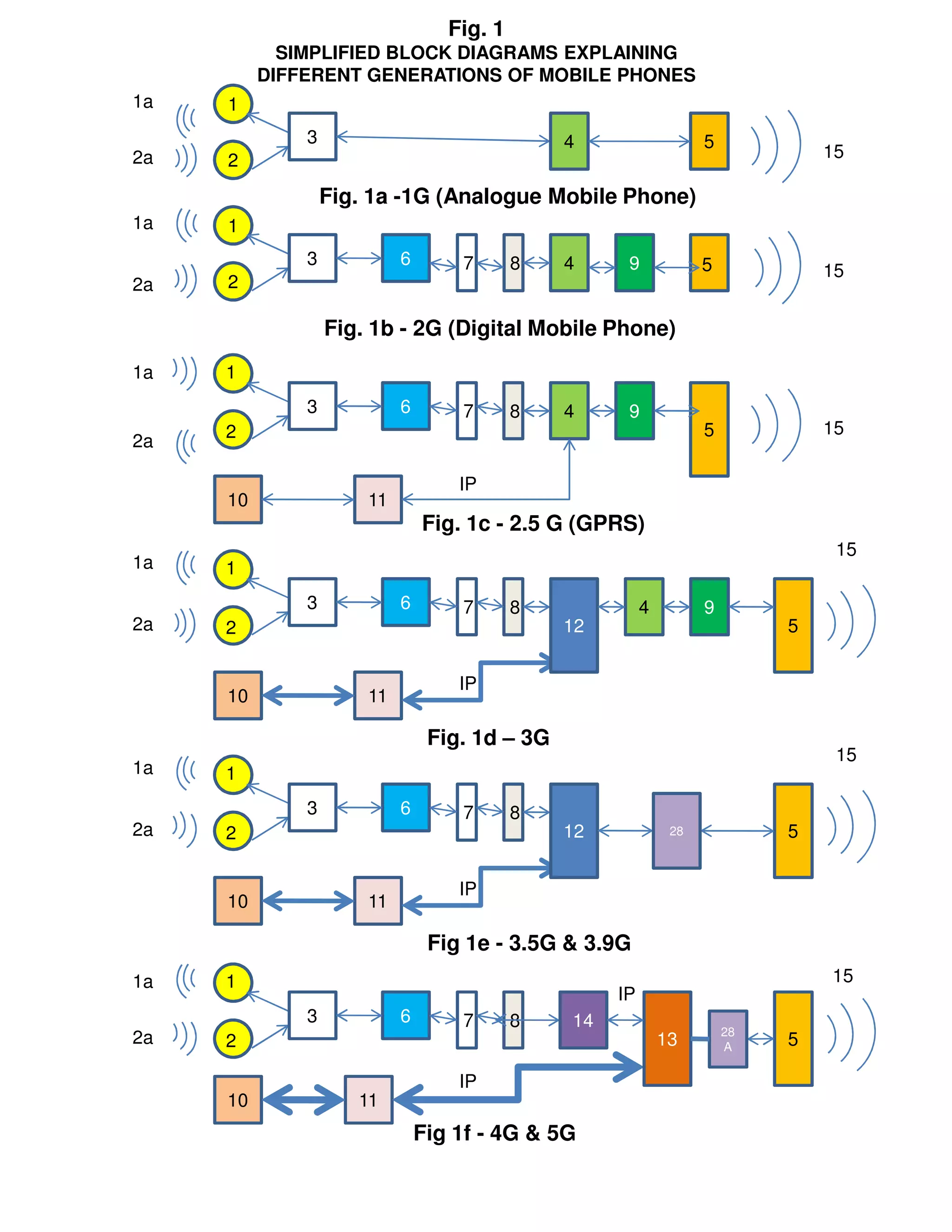
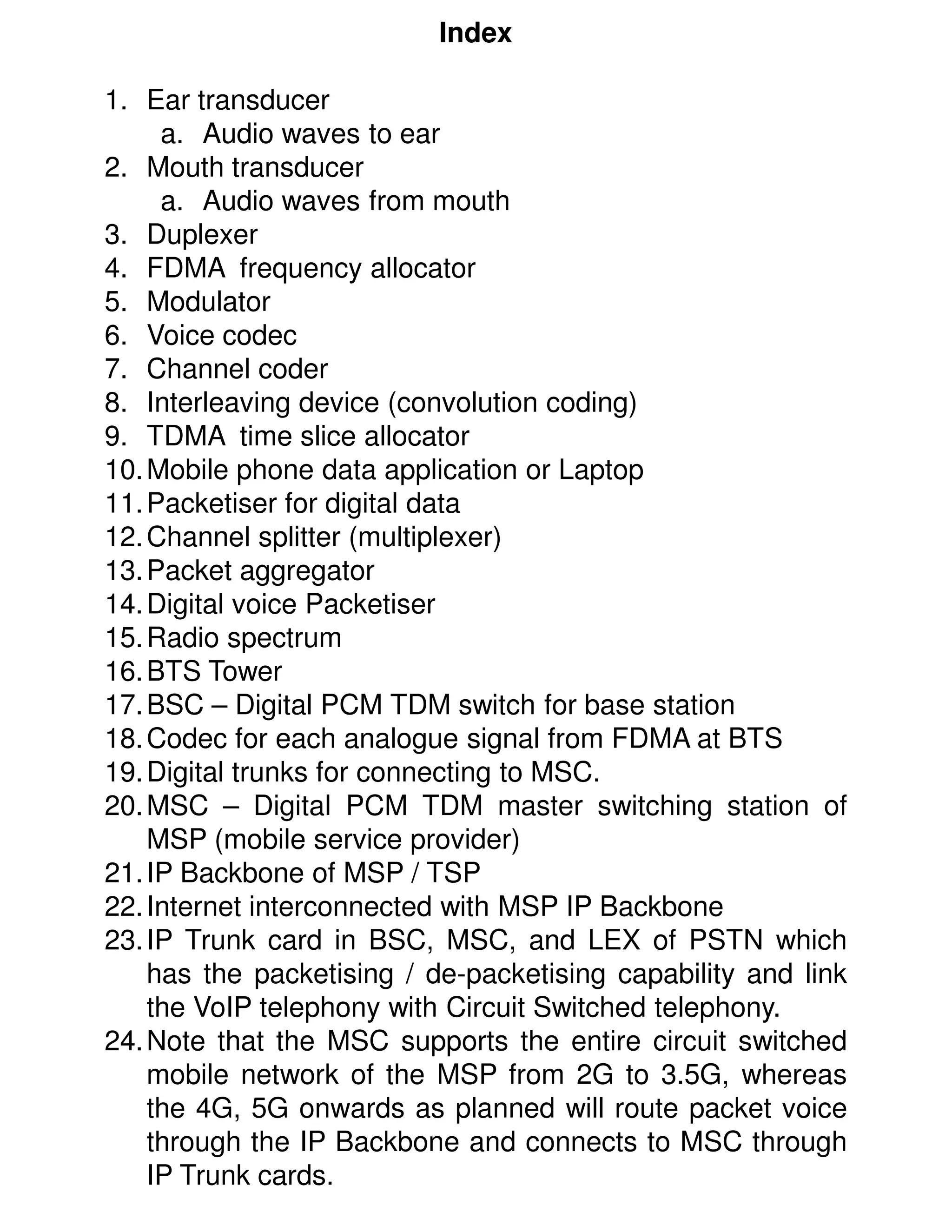
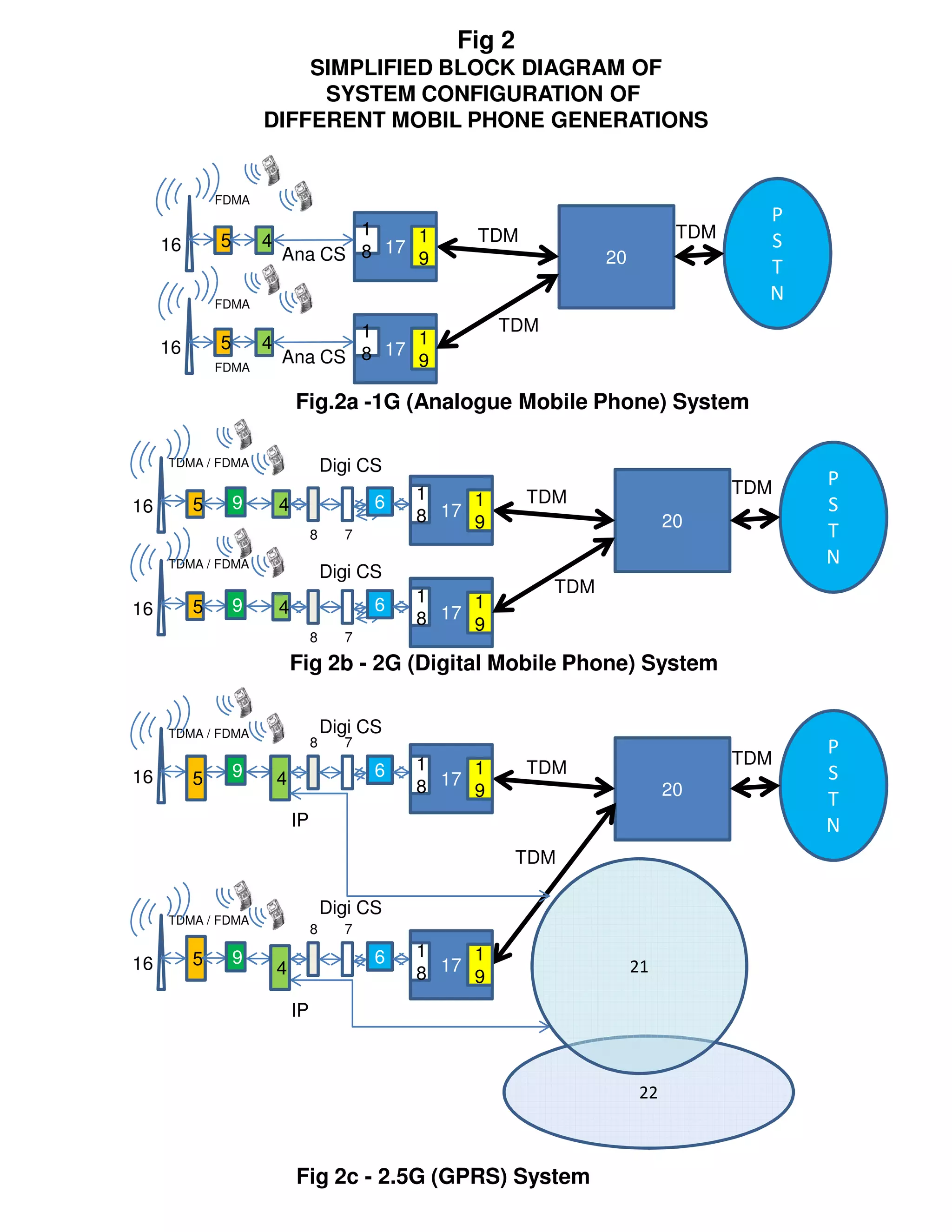
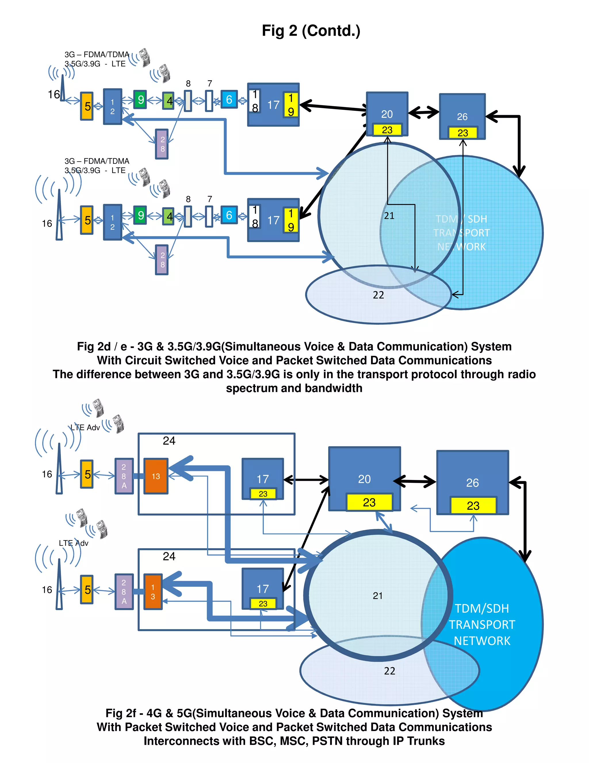
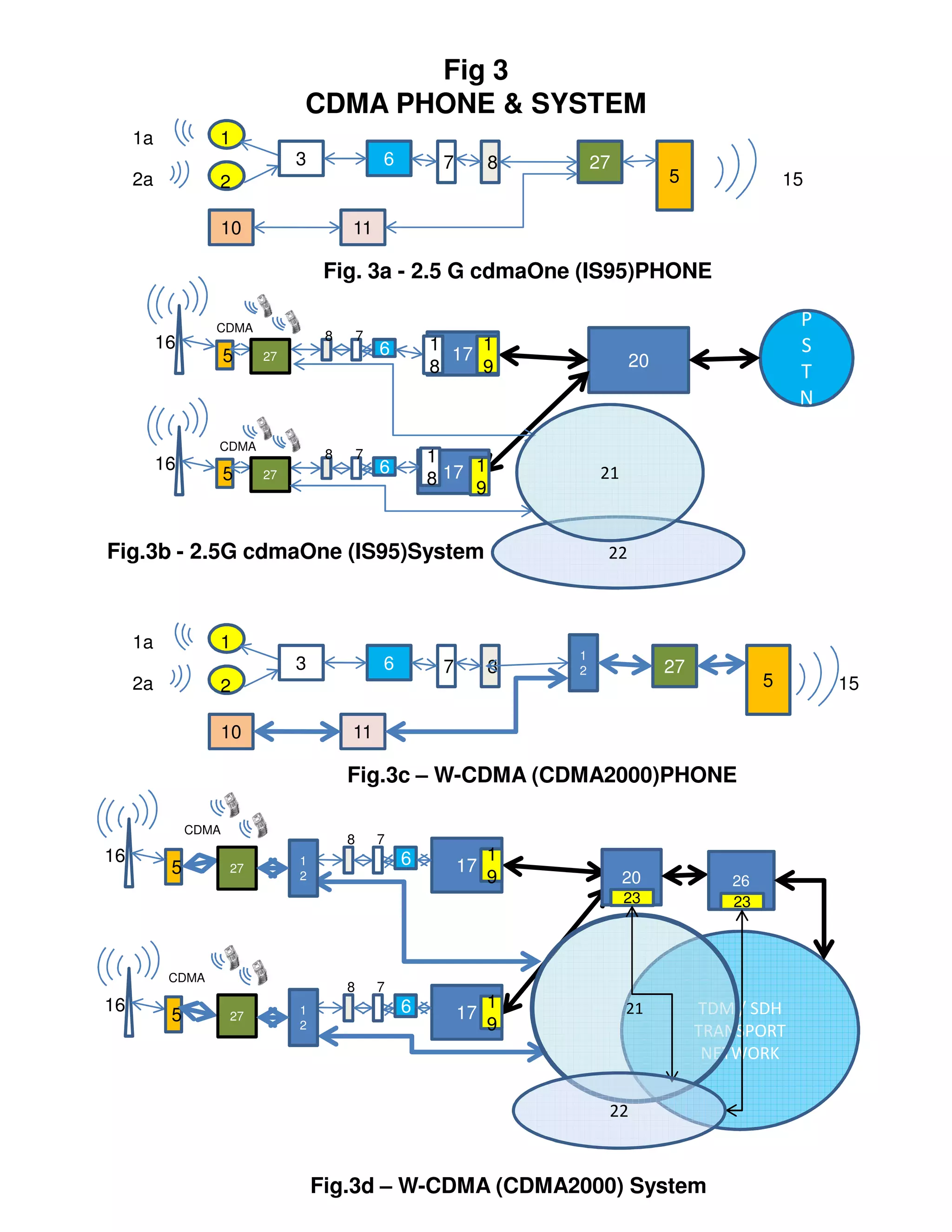
This document compares different generations of mobile phones and systems through block diagrams. It shows the evolution from 1G analog phones using FDMA to 5G phones using LTE Advanced. Key differences include how voice and data are transmitted over radio channels (circuit switched vs packetized), increasing bandwidths enabling higher speeds, and transitioning from circuit switched to packetized voice delivery.
This document provides information about the FRM220-Data fiber modem including:
- Key specifications such as supported data rates up to 9.152Mbps, optical specifications, power requirements, and environmental specifications.
- A description of the front and rear panels including LED indicators and loop back testing features.
- Explanations of the DIP switch settings for configuring items like data rate, interface protocol, timing source, and loop back mode.
- Brief descriptions of applications and clocking considerations for asymmetric data rates and extended transmission distances up to 120km.
This document is the installation and programming guide for a GSM module with 2-way voice. It contains sections on installing and connecting the module, programming it using a programming tool, and programming conventions. It also includes information on using the module's SIM card slot and starting up the module.
This document provides specifications and information for XBee and XBee-PRO OEM RF modules. Key features include long range data transmission, low power usage, analog and digital I/O support, and advanced networking capabilities. The modules operate in the 2.4GHz ISM band and are approved for use in the US, Canada, Europe and other regions. They have a small form factor and simple mounting and electrical interface.
The COM-1286 module is a PC/104 form factor integrated positioning and communication solution with an 8-channel GPS receiver and GSM 900/1800 MHz module. It has options for a GPRS or DECT module and provides navigation, tracking, data logging, timing and communication functions. The module has a fast GPS acquisition, low power consumption, and supports voice, SMS, fax and data services over GSM networks. It is compatible with various operating systems and has connectors for GPS and GSM antennas along with I/O ports.
This document provides an overview of new features and changes in Nortel's GSM BSS Performance Management — Observation Counters Fundamentals documentation for release V16.0, including the addition of new counters to support class 30/31 mobiles, improve EDGE monitoring, and monitor Gb interface throughput over frame relay. Other changes include document restructuring and updates to counters for GSM-R.
Field mobile tetra flex fmt ver 1 0 highresсергей пехов
The Field Mobile TetraFlex (FMT) is a compact yet fully functional two-carrier TETRA communication system housed in a 19" modular rack. It has been designed for flexible and rapid deployment in mobile field operations. The FMT provides mission-critical communication capabilities and can be easily integrated into larger networks. It offers scalable capacity and interoperability with other legacy communication systems.
This document summarizes the history and development of cell phones from the 1960s to the 2000s. It discusses early prototypes in the 1960s and 1970s, the first commercial cell phone in 1984, the introduction of text messaging and media content in 2G networks in the late 1980s and 1990s, and the launch of 3G networks starting in 2001 providing faster data speeds. The document traces the improvements in cell phone technology over time that made them lighter, able to store more numbers, offer longer talk times, and become more affordable and widespread.
This document summarizes the key differences between six generations of mobile phones and systems (1G to 5G). It provides simplified block diagrams of the components in each generation's phones and network systems. The main differences are in how voice and data signals are transmitted through the radio spectrum (e.g. FDMA, TDMA, CDMA, LTE), whether voice and data are sent simultaneously or separately, and whether circuit switching or packet switching is used. Later generations are able to transmit higher speeds and volumes of data using newer transmission protocols and wider radio spectrum bandwidths.
This document describes a home automation system that uses GSM technology and DTMF signaling to control devices remotely using a mobile phone. The system includes a DTMF decoder, logic ICs, transistors, and relays. Pressing buttons on the mobile phone generates DTMF tones that are decoded then used by the logic ICs to activate the relays and control electrical loads such as appliances and robots wirelessly from a distance without needing a separate remote controller.
This document describes a 10G 1554.94nm 80km DWDM SFP+ transceiver. It provides specifications for the transceiver including its product description, features, optical and electrical characteristics, and pin definitions. The transceiver uses a cooled EML laser transmitter and APD receiver to support transmission distances up to 80km over single-mode fiber for applications such as 10G Ethernet and fiber channel. It complies with relevant standards and provides digital diagnostics monitoring via a serial interface.
This document describes a 10G 1554.94nm 80km DWDM SFP+ transceiver. It provides specifications for the transceiver including its product features, functional diagram, optical and electrical characteristics, and pin definitions. The transceiver uses a cooled EML laser transmitter and APD receiver to operate over single-mode fiber for up to 80km. It supports 10G Ethernet and fiber channel applications.
This document describes a 10G 1563.05nm 80km DWDM SFP+ transceiver. It provides specifications for the transceiver including its product description, features, functional diagram, optical and electrical characteristics, and pin definitions. The transceiver uses a cooled EML laser transmitter and APD receiver to operate over single-mode fiber for up to 80km. It supports 10G Ethernet and fiber channel applications.
This document describes a 10G 1563.05nm 80km DWDM SFP+ transceiver. It provides specifications for the transceiver including its product features, functional diagram, optical and electrical characteristics, and pin definitions. The transceiver uses a cooled EML laser transmitter and APD receiver to operate over single-mode fiber for up to 80km. It supports 10G Ethernet and fiber channel applications.
This document specifies the technical details of a 10G 1562.23nm 80km DWDM SFP+ transceiver. It includes specifications for the product description, features, optical and electrical characteristics, pin definitions, serial interface, and typical interface circuit. The transceiver is designed for 10 Gigabit Ethernet links up to 80km using a cooled EML laser transmitter and APD receiver. It supports 9.95-11.3 Gb/s bit rates and operates from 0-70°C.
This document describes a 10G 1546.92nm 80km DWDM SFP+ transceiver. It provides specifications for the transceiver including its product features, functional diagram, optical and electrical characteristics, and pin definitions. The transceiver uses a cooled EML laser transmitter and APD receiver to operate over single-mode fiber for up to 80km. It supports 10G Ethernet and fiber channel applications.
This document provides specifications for a 10G 1546.92nm 80km DWDM SFP+ transceiver. It includes details on the product description, features, optical and electrical characteristics, and pin definitions. Key points are that it is designed for 10Gbps Ethernet links up to 80km, uses a cooled EML laser transmitter and APD receiver, supports digital diagnostics monitoring, and complies with relevant telecom standards.
This document specifies the technical details of a 10G 1562.23nm 80km DWDM SFP+ transceiver. It describes the product features such as supporting data rates up to 11.3 Gb/s over 80km of single mode fiber. It provides optical specifications including wavelength ranges and power levels. It also lists electrical specifications and pin definitions for the transceiver module.
This document specifies the technical details of a 10G 1548.51nm 80km DWDM SFP+ transceiver. It describes the product features, optical and electrical characteristics, channel selection, functional diagram, and pin definitions. The transceiver uses a cooled EML laser transmitter and APD receiver to support data rates up to 11.3Gb/s over 80km of single-mode fiber while complying with relevant telecom standards.
This document provides specifications for a 10G 1548.51nm 80km DWDM SFP+ transceiver. It includes details on the product description, features, optical and electrical characteristics, and pin definitions. Key points are that it uses a cooled EML laser transmitter and APD receiver to support transmission distances up to 80km over single-mode fiber at a wavelength of 1548.51nm and data rates of 9.95-11.3Gbps. It also supports digital diagnostic monitoring via a serial interface for real-time access to operating parameters.
This document specifies the technical details of a 10G 1547.72nm 80km DWDM SFP+ transceiver. It describes the product features such as supporting data rates up to 11.3 Gb/s over 80km of single mode fiber. It provides optical specifications including a center wavelength of 1547.72nm and electrical specifications such as a supply voltage range of 3.13-3.47V. It also includes pin definitions and details about the digital diagnostic monitoring interface.
This document provides specifications for a 10G 1547.72nm 80km DWDM SFP+ transceiver. It includes details on the product description, features, optical and electrical characteristics, and pin definitions. The transceiver uses a cooled EML laser transmitter and APD receiver to support transmission distances up to 80km over single-mode fiber. It also supports digital diagnostic monitoring through a 2-wire serial interface to provide real-time access to operating parameters.
This document specifies the technical details of a 10G 1554.13nm 80km DWDM SFP+ transceiver. It describes the product features such as supporting data rates up to 11.3 Gb/s, operating temperature range of 0 to 70°C, and digital diagnostic monitoring interface. It also provides optical characteristics, electrical characteristics, pin definitions and functions, and serial interface details.
This document specifies a 10G 1558.17nm 80km DWDM SFP+ transceiver. It provides details on the product description, features, channel selection, functional diagrams, optical and electrical characteristics, and pin definitions. The transceiver uses a cooled EML laser transmitter and APD photodiode receiver to operate over single-mode fiber for up to 80km. It supports 10G Ethernet and fiber channel applications.
This document specifies the technical details of a 10G 1555.75nm 80km DWDM SFP+ transceiver. It describes the product features, optical and electrical characteristics, channel selection, functional diagram, and pin definitions. The transceiver uses a cooled EML laser transmitter and APD receiver to operate over 80km of single-mode fiber at data rates up to 11.3Gbps and supports digital diagnostic monitoring via a 2-wire interface.
This document provides specifications for a 10G 1531.12nm 80km DWDM SFP+ transceiver. It includes details on the product description, features, optical and electrical characteristics, and pin definitions. Key points are that it is designed for 10GbE links up to 80km, uses a cooled EML laser transmitter and APD receiver, supports 9.95-11.3Gbps bit rates, and provides digital diagnostics monitoring via a serial interface.
This document describes a 10G 1556.55nm 80km DWDM SFP+ transceiver. It provides specifications for the transceiver including its product features, functional diagram, optical and electrical characteristics, and pin definitions. The transceiver uses a cooled EML laser transmitter and APD receiver to operate over single-mode fiber for up to 80km. It supports 10G Ethernet and fiber channel applications.
i. ISDN was initially developed to provide integrated digital services over circuit-switched networks and had advantages over traditional phone lines like supporting two simultaneous calls or data channels over one cable pair and higher data speeds.
ii. However, the rise of technologies like ADSL have reduced ISDN's advantages related to speed and capacity. Additionally, advances in traditional phone networks have reduced other ISDN benefits.
iii. Nonetheless, ISDN still has value for applications requiring synchronous connections like real-time communications, and could see renewed popularity for uses like voice-overs during remote recording or multi-location video conferencing.
The document provides a schematic of the SMS delivery gateway (SMSDG) layout and functions at the State Data Centre location. Key components include the SMSDG connected to the CBS, MNO SMSCs, IVR switch and station, and SDC. The SMSDG allows for push and pull of SMS and IVR messages between government systems and citizens' mobile phones through various networks like the NWAN, SWAN, and Internet via a secure transfer system.
The document describes a proposed National Wide Area Network (NWAN) for e-governance and m-governance in India. It involves connecting State Data Centres across states through leased lines to form the NWAN. State governments will connect to the NWAN through their respective State Data Centres. Citizen services will be delivered through State Delivery Gateways and a State Mobile Service Delivery Gateway, which will push and pull information to/from citizens through SMS and voice calls. The network aims to facilitate e-governance services and information dissemination to citizens through their mobile phones.
1. The document describes how a point-to-point leased line is built over a public switched telephone network between two cities.
2. It shows how the bandwidth of the leased line is split at each end by a channel splitter to run a circuit switched network through a VDPS router and to terminate on a data router for a private IP network.
3. The leased line paths avoid the local exchange and are directly connected to muxes for transmission between cities without mixing with public telephone trunks.
Cloud computing refers to storing and accessing data and programs over the internet instead of a computer's hard drive. The document discusses the fundamentals of cloud computing including technical descriptions, characteristics, deployment models, and issues related to privacy and security. Private clouds within an organization are important for ensuring 100% security of internal databases.
The document discusses the Next Generation Network (NGN) initiative by some telecom operators to transition from circuit-switched to packet-switched voice networks. It argues that the NGN provides few technical benefits and will require large upfront costs to upgrade infrastructure. The primary beneficiaries would be manufacturers of new network equipment, as the existing infrastructure manufacturers would lose business. Overall, subscribers and telecom providers gain little while facing higher costs, while manufacturers of new equipment push the transition mainly to create new business opportunities. The relevance and need for such a large-scale transition, given its lack of clear benefits, is questioned.
This document discusses and compares VoIP (Voice over Internet Protocol) and PSTN (Public Switched Telephone Network) networks. It provides details on the evolution and architecture of PSTN networks and how they facilitate voice communications. It also describes how IP networks were developed for higher speed data and internet access. While most telecom providers built separate networks for voice and data, some now offer VoIP over their IP networks. The document analyzes advantages and disadvantages of carrying voice calls over IP networks versus circuit-switched networks like PSTN. It argues that a mixed network approach using both is most cost effective and ensures quality for real-time communications like voice and video.
Circuit switched telephone networks transmit digitized voice signals over dedicated circuits, while packet switched networks divide voice signals into packets which are transmitted over shared networks. In circuit switched networks, a connection is established end-to-end for each call, while in packet switched networks multiple communications share network bandwidth through packetization. Packetization allows better utilization of bandwidth for bursty data traffic as in computer networks, while circuit switched networks ensure utilization through traffic engineering. Voice can be transmitted over packet networks by digitizing it and transmitting the voice packets alongside data packets.
This explains the path-breaking patented technology which can ensure 100% security of an organisation's internal databases. This is used in conjunction with the PVDTN connectivity solution.
VPN and MPLS VPN networks are inherently vulnerable because they run over telecom providers' IP networks, which also carry public internet traffic. While convenient for IT teams, these networks allow databases connected via VPN to be potentially accessed from the public domain. Setting up private leased line networks requires more initial work but eliminates this vulnerability, providing true security and a trouble-free experience for network administrators in the long run. The document argues that the easy choice of a VPN introduces future risks, while the harder choice of a private network is actually easier to manage over time.
1. The document describes the topology and architecture of a typical ISP's IP network that provides both internet and VPN services. It shows how different cities are connected in a mesh and hierarchical structure.
2. It explains that within each node, the core router sits on a tier 1 switch that connects to all edge routers providing VPN, internet, and PSTN services. This allows continuous physical connectivity and access between all routers on the public network.
3. Because of this continuous connectivity between public routers, a hacker could potentially access a VPN customer's private network even while security protocols like IPSec are being used between the customer's devices. The customer's LAN and databases are therefore exposed on a VPN with
The document compares the costs of MPLS VPN connectivity versus point-to-point leased line connectivity for links over 500km and within a city. For long-distance cross-country links over 500km, the point-to-point leased line option is 58.73-74.3% cheaper than the MPLS VPN option even after discounts. Similarly for intra-city links, point-to-point leased lines are 20.21-20.73% cheaper. The tables provide a detailed cost breakdown and comparison of the different cost components for each connectivity option.
The document provides answers to four frequently asked questions about PVDTN, an integrated voice, fax, and data network solution.
1. It explains how PVDTN saves costs by replacing traditional telephony networks with a circuit-switched voice/fax network and separate IP data network over the same leased lines. This reduces total communication costs compared to maintaining separate voice and data networks.
2. PVDTN maintains separate networks that are managed independently, so existing teams can continue their roles without conflict.
3. PVDTN is more bandwidth efficient than VOIP alone and ensures sufficient bandwidth to avoid call blocking or quality issues, further reducing costs compared to VOIP implementations.
4. Web collaboration
The document discusses the benefits of a private voice-data telecom network (PVDTN) system. It outlines how PVDTN can save organizations up to 75% of present telecom costs, improve decision making and security, and virtually convert multi-location organizations into single offices. The document provides diagrams illustrating sample network configurations and topologies that can be implemented using PVDTN to integrate voice, fax and data communications across locations.
More from MIDAS Automation & Telecommunications Pvt. Ltd. (MIDAUTEL) (15)
Exploiting Artificial Intelligence for Empowering Researchers and Faculty, In...Dr. Vinod Kumar Kanvaria
Exploiting Artificial Intelligence for Empowering Researchers and Faculty,
International FDP on Fundamentals of Research in Social Sciences
at Integral University, Lucknow, 06.06.2024
By Dr. Vinod Kumar Kanvaria
Strategies for Effective Upskilling is a presentation by Chinwendu Peace in a Your Skill Boost Masterclass organisation by the Excellence Foundation for South Sudan on 08th and 09th June 2024 from 1 PM to 3 PM on each day.
The simplified electron and muon model, Oscillating Spacetime: The Foundation...RitikBhardwaj56
Discover the Simplified Electron and Muon Model: A New Wave-Based Approach to Understanding Particles delves into a groundbreaking theory that presents electrons and muons as rotating soliton waves within oscillating spacetime. Geared towards students, researchers, and science buffs, this book breaks down complex ideas into simple explanations. It covers topics such as electron waves, temporal dynamics, and the implications of this model on particle physics. With clear illustrations and easy-to-follow explanations, readers will gain a new outlook on the universe's fundamental nature.
Main Java[All of the Base Concepts}.docxadhitya5119
This is part 1 of my Java Learning Journey. This Contains Custom methods, classes, constructors, packages, multithreading , try- catch block, finally block and more.
How to Fix the Import Error in the Odoo 17Celine George
An import error occurs when a program fails to import a module or library, disrupting its execution. In languages like Python, this issue arises when the specified module cannot be found or accessed, hindering the program's functionality. Resolving import errors is crucial for maintaining smooth software operation and uninterrupted development processes.
How to Manage Your Lost Opportunities in Odoo 17 CRMCeline George
Odoo 17 CRM allows us to track why we lose sales opportunities with "Lost Reasons." This helps analyze our sales process and identify areas for improvement. Here's how to configure lost reasons in Odoo 17 CRM
it describes the bony anatomy including the femoral head , acetabulum, labrum . also discusses the capsule , ligaments . muscle that act on the hip joint and the range of motion are outlined. factors affecting hip joint stability and weight transmission through the joint are summarized.
How to Setup Warehouse & Location in Odoo 17 InventoryCeline George
In this slide, we'll explore how to set up warehouses and locations in Odoo 17 Inventory. This will help us manage our stock effectively, track inventory levels, and streamline warehouse operations.
How to Add Chatter in the odoo 17 ERP ModuleCeline George
In Odoo, the chatter is like a chat tool that helps you work together on records. You can leave notes and track things, making it easier to talk with your team and partners. Inside chatter, all communication history, activity, and changes will be displayed.
How to Make a Field Mandatory in Odoo 17Celine George
In Odoo, making a field required can be done through both Python code and XML views. When you set the required attribute to True in Python code, it makes the field required across all views where it's used. Conversely, when you set the required attribute in XML views, it makes the field required only in the context of that particular view.
हिंदी वर्णमाला पीपीटी, hindi alphabet PPT presentation, hindi varnamala PPT, Hindi Varnamala pdf, हिंदी स्वर, हिंदी व्यंजन, sikhiye hindi varnmala, dr. mulla adam ali, hindi language and literature, hindi alphabet with drawing, hindi alphabet pdf, hindi varnamala for childrens, hindi language, hindi varnamala practice for kids, https://www.drmullaadamali.com
BÀI TẬP BỔ TRỢ TIẾNG ANH 8 CẢ NĂM - GLOBAL SUCCESS - NĂM HỌC 2023-2024 (CÓ FI...
Mobile
1. COMPARISON OF
DIFFERENT MOBILE PHONE GENERATIONS
PHONES & SYSTEMS
This document explains the different generations of mobile
telephony with simplified block diagrams.
2. 1. Figure 1 shows simplified block diagrams of the different
Generations of mobile phones – 1G, 2G, 2.5G, 3G &
3.5G, 4G, and 5G.
2. Figure 2 shows the simplified block diagrams of the
different Generations of mobile phone systems – 1G, 2G,
2.5G, 3G & 3.5, 4G, and 5G.
3. Uniform numbering has been used throughout so that the
differences may be easily perceptible.
4. The first basic difference in the different generation
phones and systems lies in the manner signals from the
phone are transported through the radio spectrum
available – FDMA, FDMA/TDMA, CDMA, LTE, and LTE
Advanced.
5. The second basic difference lies in circuit switching voice
and IP data sent alternately through a single radio
channel, and simultaneous transmission of voice and data
either using circuit switched voice and IP data through a
channel splitter, or using packetised voice sent along with
data packets in queue over the single radio channel.
6. The receiving system from the BTS (tower) onwards have
to adapt to these different types of signals received
through the radio spectrum.
7. Fig.1a shows the 1G phone block diagram and Fig. 2a
shows the 1G system block diagram.
8. Fig. 1b shows the 2G phone block diagram and Fig. 2b
shows the 2G system block diagram.
9. Fig. 1c shows the 2.5G phone block diagram and Fig. 2c
shows the 2.5G system block diagram.
10. Fig. 1d shows the 3G phone block diagram and Fig. 2d
shows the 3G system block diagram.
11. Fig. 1e shows the 3.5 and 3.9G phone block diagram and
Fig. 2e shows the 3.5 and 3.9G system block diagram.
12. Fig. 1f shows the 4G and 5G phone block diagram and
Fig. 2f shows the 4G and 5G system block diagram.
3. 13. Fig.3a shows the simplified block diagram of the
cdmaOne phone (IS 95) and Fig.3b shows the
corresponding system diagram.
14. Fig.3c shows the simplified block diagram of the
W-CDMA (CDMA 2000) and Fig.3b shows the
corresponding system diagram.
15. In the 3G, 3.5G, 3.9G, and the CDMA2000 phones
simultaneous voice and data is carried out over a
single radio channel through a channel splitter (12)
shown in the block diagrams. The voice is circuit
switched end-to-end. 3G uses FDMA/TDMA
transmission protocol over the radio spectrum. 3.5G
and 3.9G use the 3GPP LTE protocol over radio
spectrum, a scalable frequency spectrum of 1.5 MHz
to 20 MHz and supports both FDD (frequency
division duplexing) and TDD (time division duplexing)
and can produce a download speed of 100Mbps and
an upload speed of 50 Mbps with a round trip delay of
10 ms.
16. In the 4G, 5G, onward phones the voice is packetised
and aggregated with the data packets and the
combined packets are routed via the LTE Advanced
transportation across the radio frequency spectrum.
Various techniques like MIMO are used to get higher
spectral efficiency, and lower latency, to get better
performance on real time communications like voice
and video. Besides the system works with higher
bandwidth and works over a range of frequency
spectrum from 20 MHz to 100 MHz. Using 100 MHz
frequency bandwidth it is possible to achieve 5 Gbps
download to a mobile station moving at 10 Km./Hr.
17.The basic difference between 3.5G/3.9G phone and
the 4G flat IP phone is the channel splitter is replaced
by the voice Packetiser and Packet Aggregator, and
the replacement of LTE with LTE Advanced.
5. Index
1. Ear transducer
a. Audio waves to ear
2. Mouth transducer
a. Audio waves from mouth
3. Duplexer
4. FDMA frequency allocator
5. Modulator
6. Voice codec
7. Channel coder
8. Interleaving device (convolution coding)
9. TDMA time slice allocator
10. Mobile phone data application or Laptop
11. Packetiser for digital data
12. Channel splitter (multiplexer)
13. Packet aggregator
14. Digital voice Packetiser
15. Radio spectrum
16. BTS Tower
17. BSC – Digital PCM TDM switch for base station
18. Codec for each analogue signal from FDMA at BTS
19. Digital trunks for connecting to MSC.
20. MSC – Digital PCM TDM master switching station of
MSP (mobile service provider)
21. IP Backbone of MSP / TSP
22. Internet interconnected with MSP IP Backbone
23. IP Trunk card in BSC, MSC, and LEX of PSTN which
has the packetising / de-packetising capability and link
the VoIP telephony with Circuit Switched telephony.
24. Note that the MSC supports the entire circuit switched
mobile network of the MSP from 2G to 3.5G, whereas
the 4G, 5G onwards as planned will route packet voice
through the IP Backbone and connects to MSC through
IP Trunk cards.
6. 25. Base Station Building containing Packet aggregator,
Data Packetiser, Voice Packetiser, and connection to
POP of IP Backbone
26. LEX (local exchange) of PSTN .
27. CDMA multiplexer
28. LTE
28A. LTE Advanced
7. Fig 2
SIMPLIFIED BLOCK DIAGRAM OF
SYSTEM CONFIGURATION OF
DIFFERENT MOBIL PHONE GENERATIONS
FDMA
P
1 1 TDM TDM
16 5 4 S
Ana CS 8 17 9 20
T
FDMA
N
1 TDM
5 4 1
16
FDMA
Ana CS 8 17 9
Fig.2a -1G (Analogue Mobile Phone) System
TDMA / FDMA Digi CS
TDM P
9 6 1 1 TDM
16 5 4
8 17 9
S
20
8 7 T
TDMA / FDMA N
Digi CS
TDM
9 6 1 1
16 5 4
8 17 9
8 7
Fig 2b - 2G (Digital Mobile Phone) System
TDMA / FDMA Digi CS
8 7 P
1 TDM TDM
16 9 6 1 S
5 4 8 17 9 20
T
IP N
TDM
Digi CS
TDMA / FDMA
8 7
5 9 6 1 1
16 4 8 17 9 21
IP
22
Fig 2c - 2.5G (GPRS) System
8. Fig 2 (Contd.)
3G – FDMA/TDMA
3.5G/3.9G - LTE
8 7
16 9 6 1 1
1 4
5 2 8 17 9 20 26
23 23
2
8
3G – FDMA/TDMA
3.5G/3.9G - LTE
8 7
9 6 1 1 21
5 1 4 TDM / SDH
16 2 8 17 9
TRANSPORT
NETWORK
2
8
22
Fig 2d / e - 3G & 3.5G/3.9G(Simultaneous Voice & Data Communication) System
With Circuit Switched Voice and Packet Switched Data Communications
The difference between 3G and 3.5G/3.9G is only in the transport protocol through radio
spectrum and bandwidth
LTE Adv
24
2
16 5 8 13
17 20
A 26
23
23 23
LTE Adv
24
2
16 5 1 17
8
3 21
A 23
TDM/SDH
TRANSPORT
NETWORK
22
Fig 2f - 4G & 5G(Simultaneous Voice & Data Communication) System
With Packet Switched Voice and Packet Switched Data Communications
Interconnects with BSC, MSC, PSTN through IP Trunks