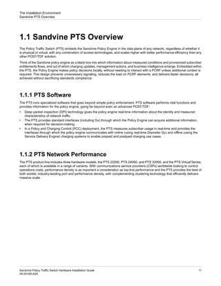
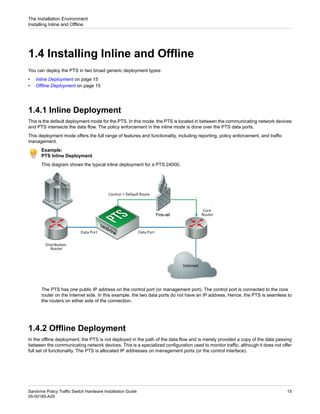
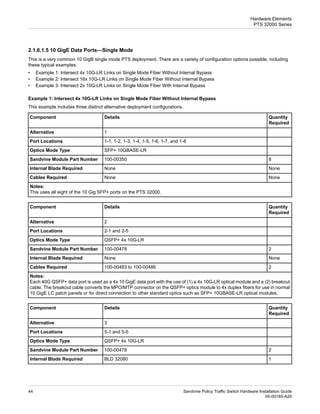
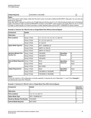
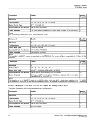
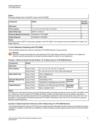
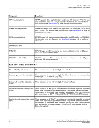
The Sandvine Policy Traffic Switch (PTS) embeds the Sandvine Policy Engine in network data planes to make policy decisions locally without unnecessary signaling. PTS software performs deep packet inspection and provides standard interfaces to acquire additional information for decision making. PTS measures subscriber usage in real-time and communicates with charging systems online using Diameter Gy and offline using file-based protocols. PTS platforms are available in different throughput capacities and can be clustered for additional scalability.


![15. Turn the power on.
16. Wait for all system services to come online before verifying the blade. See PTS 22000, PTS 24000, and PTS 32000 Blade
LEDs on page 115.
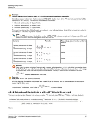
17. Run the show system blades CLI command to verify the blade. This should generate output similar to:
CLI> show system blades
Blade InterfaceSlot Model OperStatus SerialNumber
------ ------------- -------- ---------- ------------
1 1 BLD24020 [up] 0123456789
2 2 BLD24042 [up] 0123456789
The front panel interfaces on the PTS are prefixed with an Interface Slot identifier, which can be different from the Blade
Slot identifier. For example, a blade on PTS 22000 provides interfaces belonging to Interface Slot 2 (that is, 2-1, 2-2, 2-3,
etc.), while the Blade Slot identifier is 1.
See this table for additional information.
Interface Slot
Blade Slot
Model
2
1
PTS 22000
1
1
PTS 24000
2
2
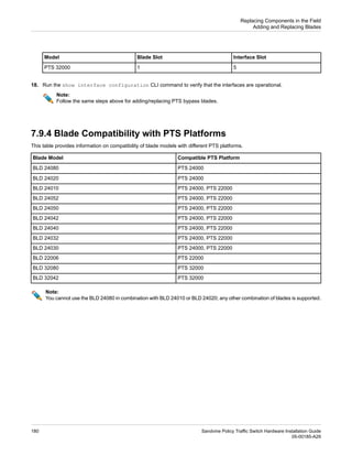
18. Run the show interface configuration CLI command to verify that the interfaces are operational.
Note:
Follow the same steps above for adding/replacing PTS bypass blades.
7.9.3 Adding and Replacing Blades in PTS 32000
Perform these steps to remove or replace an I/O blade in the PTS 32000:
1. Upgrade the PTS to a software version that supports the blade model that you want to install.
Examples:
Supported PTS Software Version
I/O Blade Model
PTS 7.00.01 or later
BLD 32042
PTS 7.10.00 or later
BLD 32080
See 2.1 Downgrade Compatibility for PTS Hardware in the PTS Software Installation Guide for additional information on
supported PTS software versions.
2. Ensure the hardware compatibility of the blade model with PTS 32000. See Blade Compatibility with PTS Platforms on
page 180 for more information.
3. Perform this additional step when installing BLD 32080 in a PTS 32000, before proceeding to the next step.
A firmware upgrade and subsequent PTS power cycle are required to support the BLD 32080 in PTS 32000. Contact
Sandvine Customer Support, or its authorized partner, for additional information.
Sandvine Policy Traffic Switch Hardware Installation Guide
176
05-00185-A29
Replacing Components in the Field
Adding and Replacing Blades](https://image.slidesharecdn.com/ptshardwareinstallationguidea29-230112003821-84bb4ec4/85/PTS_Hardware_Installation_Guide_A29-pdf-176-320.jpg)


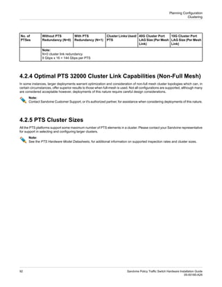
![12. Ensure that the blade is fully inserted by pushing on the outer edges of the blade with both thumbs. The blade face plate
should be flush with the chassis face plate.
13. Tighten both screws on the blade.
Note:
Tighten the screw gently by hand, at first, to ensure that there is no cross-threading of the screw.
14. Insert any optical interfaces and then reconnect the cables.
15. Turn the power on.
16. Wait for all system services to come online before verifying the blade. See PTS 22000, PTS 24000, and PTS 32000 Blade
LEDs on page 115.
17. Run the show system blades CLI command to verify the blade. This should generate output similar to:
CLI> show system blades
Blade InterfaceSlot Model OperStatus SerialNumber
------ ------------- -------- ---------- --------------
1 5 BLD32080 [up] 01234567890123
The front panel interfaces on the PTS are prefixed with an Interface Slot identifier, which can be different from the Blade
Slot identifier.
See this table for additional information.
179
Sandvine Policy Traffic Switch Hardware Installation Guide
05-00185-A29
Replacing Components in the Field
Adding and Replacing Blades](https://image.slidesharecdn.com/ptshardwareinstallationguidea29-230112003821-84bb4ec4/85/PTS_Hardware_Installation_Guide_A29-pdf-179-320.jpg)