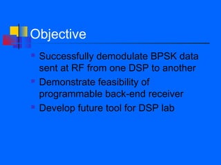
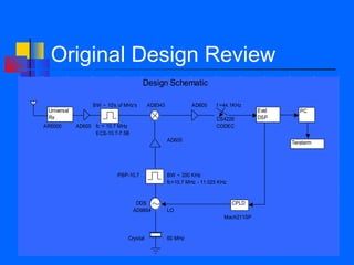
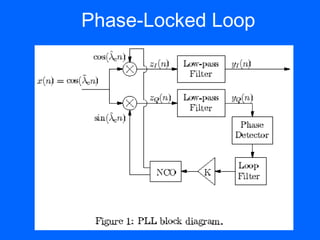
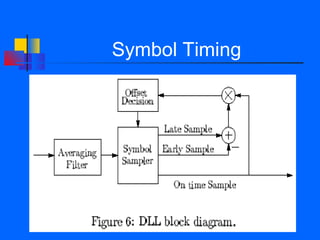
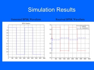
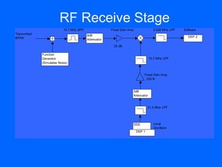
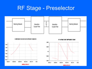
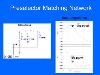
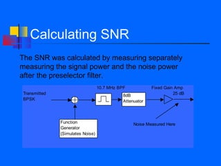
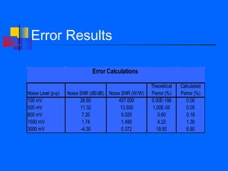
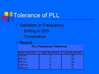
BPSK RF Receiver

      Team 10
   Michael Russell
     Shawn Kuo
     Amit Patel
Objective
   Successfully demodulate BPSK data
    sent at RF from one DSP to another
   Demonstrate feasibility of
    programmable back-end receiver
   Develop future tool for DSP lab
End-user Benefits
   A quick and simple point-to-point digital
    communication solution
   Scalable module that is capable of
    handling multiple demodulation
    schemes without hardware redesign
   Capable of receiving over a large
    frequency range
Original Design Review
                                        Design Schematic

                   BW ~ 10's of MHz's      AD8343             AD605     f =44.1KHz
 Universal                                                                             Eval      PC
 Rx                                                                     CS4226         DSP
AR5000       AD605 fc = 10.7 MHz                                        CODEC
                   ECS-10.7-7.5B
                                                    AD605                                     Teraterm


                             PBP-10.7               BW ~ 200 KHz
                                                    fc=10.7 MHz - 11.025 KHz


                                    DDS                                        CPLD
                                   AD9854           LO
                                                                           Mach211SP


                                 Crystal            60 MHz
Software Implementation
   Differential BPSK
       Pi-Radian Ambiguity
       Symbol Quantization and Unmapping
   Phase-Locked Loop
       Carrier Recovery
       Coherent Detection
   Symbol Timing
Differential BPSK Symbol Mapping
Phase-Locked Loop
Symbol Timing
Simulation Results
Generated BPSK Waveform   Received BPSK Waveform
RF Receive Stage
                            10.7 MHz BPF                Fixed Gain Amp              0.528 MHz LPF   Software
Transmitted                                8dB
BPSK                                                                                                  DSP 2
                                           Attenuator

                                                         25 dB

              Function
              Generator                                                           10.7 MHz LPF
              (Simulates Noise)


                                                                             Fixed Gain Amp
                                                                              25d B


                                                                     3dB
                                                                     Attenuator


                                                                                 21.4 MHz LPF


                                                                     DDS            Local
                                                                                    Oscillator
                                                                         DSP 1
RF Stage - Preselector

                                Maching Network                  Monolithic                                       Monolithic                      Maching Network
                                                                Crystal Filter                                    Crystal Filter


                                 Ta se F n t no Pe e c rd )
                                  rn fr u cio f rs l t ( B
                                                    eo                                                                             P ae f rsl t
                                                                                                                                    h s o Pee c r
                                                                                                                                             eo
                       0
   h g e r_3 ( ,1)


                                                                                                          20
                                                                                                           0
...cin _N tok ..S2 )


                                                                                     c g ewr_3 ( ,1)
                                                                                  ...t in _N tok ..S2 )
                       -0
                       1
                                                                                                          10
                                                                                                           0
                       -0
                       2

                       -0
                       3
          w


                                                                                                           0
                       -0
                       4

                                                                                                          -0
                                                                                                          10
                       -0
                       5
                                                                                      h


                       -0
                       6
                                                                                                          -0
                                                                                                          20
                        1 .6
                         0 7   1 .6
                                0 8    1 .6
                                        0 9       1 .7
                                                   0 0   1 .7
                                                          0 1      1 .7
                                                                    0 2          1 .7
                                                                                  0 3
                                                                                                           1 .6
                                                                                                            07       1 .6
                                                                                                                      08           1 .6
                                                                                                                                    09     1 .7
                                                                                                                                            00      1 .7
                                                                                                                                                     01       1 .7
                                                                                                                                                               02    1 .7
                                                                                                                                                                      03
                                              f qM z
                                              r , H
                                               e
                                                                                                                                          f qM z
                                                                                                                                          r , H
                                                                                                                                           e
Preselector Matching Network
                                                        Input Impedance
                                                     30
                                                      50

                                                                         m1
                  Matching Network                   30
                                                      00          m1     fq 0 0 H
                                                                         r =1 .7 M z
                                                                          e
                                                                         Rn 7 7 5
                                                                          i =2 5 .7 6
                                                     20
                                                      50


                                      R              20
                                                      00


                                                in
                      C     L


                                               R
                                      R2             10
                                                      50

                      C1    L2
                                      R=5 Oh
                                         0 m
                      C=4 p L .8 u
                         0 F =5 5 H
                                                     10
                                                      00


                            R=                        50
                                                       0


                                                       0

                                                     10
                                                      50


                                                     10
                                                      00


                                                      50
                                                       0


                                                                  m 2
Zin = 2580 - j 1040                        `   Xn
                                                i
                                                       0
                                                                  fq 0 0 H
                                                                  r =1 .7 M z
                                                                   e
                                                                  X =- 0 3 4
                                                                   in 1 3 .4 8
                                                     - 0
                                                      50

                                                                  m2
                                                     - 00
                                                      10


                                                     - 50
                                                      10


                                                     - 00
                                                      20
                                                        1 .0
                                                         0     1 .5
                                                                0      1 .0
                                                                        1     1 .5
                                                                               1     1 .0
                                                                                      2

                                                                      fqM z
                                                                      r , H
                                                                       e
Measured Signals
   Transmitted signal
   Signal after preselector
   Signal after mixing (baseband)
   Unfiltered DDS signal (LO)
   Filtered DDS signal
Transmitted Signal
Filtered Signal
Filtered Signal
Baseband Signal
Unfiltered DDS (LO)
Filtered DDS (LO)
Output Interface
   Write decoded characters to memory
    and serial port simultaneously
   Interact with serial port through Tera
    Term
Theoretical Probability of Error
                           Q


Constellation
                                          I
                Symbol B       Symbol A


                           Q


Constellation
w/Noise                                   I

                Symbol B       Symbol A
Theoretical Probability of Error
                  Received Symbol:
Mapping                              Q


                                                    I


                      Symbol B           Symbol A


Result: Q(sqrt(2*Energy/Noise)) or Q(sqrt(2*SNR))
Calculating SNR
The SNR was calculated by measuring separately
measuring the signal power and the noise power
after the preselector filter.
                                  10.7 MHz BPF            Fixed Gain Amp
Transmitted                                  8dB                    25 dB
BPSK                                         Attenuator


              Function                            Noise Measured Here
              Generator
              (Simulates Noise)
Calculated Probability of Error
   Calculated Byte Error (upper bound)
   Took 125KB of data
       Accurate for large amounts of noise
       Good order of magnitude approximation for
        low noise
Error Results

                              Error Calculations

                                                        Theoretical   Calculated
Noise Level (p-p)   Noise SNR (dB/dB) Noise SNR (W/W)   Perror (%)    Perror (%)
100 mV                    26.60            457.000      5.00E-199        0.00
500 mV                    11.32             13.550       1.00E-05        0.05
800 mV                     7.20             5.025           0.60         0.18
1500 mV                    1.74             1.490           4.22         1.30
3000 mV                    -4.30            0.372          19.50         6.80
Tolerance of PLL
   Variation in Frequency
         Drifting in DDS
         Temperature
   Result
                PLL Frequency Tolerance

    Noise Level (p-p)   Upper Bound (Hz)   Lower Bound (Hz)
    100 mV                     9                 -32
    500 mV                     8                 -32
    800 mV                     8                 -32
    1500 mV                    8                 -32
    3000 mV                    8                 -31
Successes
   Demodulated BPSK data sent at RF
    from one DSP to another
   Demonstrated feasibility of
    programmable back-end receiver
   Breadboard design produced expected
    behavior
Challenges
   Transmitting BPSK signal at RF
       Used passive mixer and DDS
       Used coaxial channel instead of air
   Bandlimiting Signal
       Use of Narrow Bandwidth Crystal Filter
       Matching Network
   Working around Serial Port interrupts
Future Developments Rev1.1
   Solve Serial Port Issues for live data
   Printed Circuit Board
   Add Faster A/D
   Implement more Demodulation
    Schemes
Questions???

Project10 presentation

  • 1.
    BPSK RF Receiver Team 10 Michael Russell Shawn Kuo Amit Patel
  • 2.
    Objective  Successfully demodulate BPSK data sent at RF from one DSP to another  Demonstrate feasibility of programmable back-end receiver  Develop future tool for DSP lab
  • 3.
    End-user Benefits  A quick and simple point-to-point digital communication solution  Scalable module that is capable of handling multiple demodulation schemes without hardware redesign  Capable of receiving over a large frequency range
  • 4.
    Original Design Review Design Schematic BW ~ 10's of MHz's AD8343 AD605 f =44.1KHz Universal Eval PC Rx CS4226 DSP AR5000 AD605 fc = 10.7 MHz CODEC ECS-10.7-7.5B AD605 Teraterm PBP-10.7 BW ~ 200 KHz fc=10.7 MHz - 11.025 KHz DDS CPLD AD9854 LO Mach211SP Crystal 60 MHz
  • 5.
    Software Implementation  Differential BPSK  Pi-Radian Ambiguity  Symbol Quantization and Unmapping  Phase-Locked Loop  Carrier Recovery  Coherent Detection  Symbol Timing
  • 6.
  • 7.
  • 8.
  • 9.
    Simulation Results Generated BPSKWaveform Received BPSK Waveform
  • 10.
    RF Receive Stage 10.7 MHz BPF Fixed Gain Amp 0.528 MHz LPF Software Transmitted 8dB BPSK DSP 2 Attenuator 25 dB Function Generator 10.7 MHz LPF (Simulates Noise) Fixed Gain Amp 25d B 3dB Attenuator 21.4 MHz LPF DDS Local Oscillator DSP 1
  • 11.
    RF Stage -Preselector Maching Network Monolithic Monolithic Maching Network Crystal Filter Crystal Filter Ta se F n t no Pe e c rd ) rn fr u cio f rs l t ( B eo P ae f rsl t h s o Pee c r eo 0 h g e r_3 ( ,1) 20 0 ...cin _N tok ..S2 ) c g ewr_3 ( ,1) ...t in _N tok ..S2 ) -0 1 10 0 -0 2 -0 3 w 0 -0 4 -0 10 -0 5 h -0 6 -0 20 1 .6 0 7 1 .6 0 8 1 .6 0 9 1 .7 0 0 1 .7 0 1 1 .7 0 2 1 .7 0 3 1 .6 07 1 .6 08 1 .6 09 1 .7 00 1 .7 01 1 .7 02 1 .7 03 f qM z r , H e f qM z r , H e
  • 12.
    Preselector Matching Network Input Impedance 30 50 m1 Matching Network 30 00 m1 fq 0 0 H r =1 .7 M z e Rn 7 7 5 i =2 5 .7 6 20 50 R 20 00 in C L R R2 10 50 C1 L2 R=5 Oh 0 m C=4 p L .8 u 0 F =5 5 H 10 00 R= 50 0 0 10 50 10 00 50 0 m 2 Zin = 2580 - j 1040 ` Xn i 0 fq 0 0 H r =1 .7 M z e X =- 0 3 4 in 1 3 .4 8 - 0 50 m2 - 00 10 - 50 10 - 00 20 1 .0 0 1 .5 0 1 .0 1 1 .5 1 1 .0 2 fqM z r , H e
  • 13.
    Measured Signals  Transmitted signal  Signal after preselector  Signal after mixing (baseband)  Unfiltered DDS signal (LO)  Filtered DDS signal
  • 14.
  • 15.
  • 16.
  • 17.
  • 18.
  • 19.
  • 20.
    Output Interface  Write decoded characters to memory and serial port simultaneously  Interact with serial port through Tera Term
  • 21.
    Theoretical Probability ofError Q Constellation I Symbol B Symbol A Q Constellation w/Noise I Symbol B Symbol A
  • 22.
    Theoretical Probability ofError Received Symbol: Mapping Q I Symbol B Symbol A Result: Q(sqrt(2*Energy/Noise)) or Q(sqrt(2*SNR))
  • 23.
    Calculating SNR The SNRwas calculated by measuring separately measuring the signal power and the noise power after the preselector filter. 10.7 MHz BPF Fixed Gain Amp Transmitted 8dB 25 dB BPSK Attenuator Function Noise Measured Here Generator (Simulates Noise)
  • 24.
    Calculated Probability ofError  Calculated Byte Error (upper bound)  Took 125KB of data  Accurate for large amounts of noise  Good order of magnitude approximation for low noise
  • 25.
    Error Results Error Calculations Theoretical Calculated Noise Level (p-p) Noise SNR (dB/dB) Noise SNR (W/W) Perror (%) Perror (%) 100 mV 26.60 457.000 5.00E-199 0.00 500 mV 11.32 13.550 1.00E-05 0.05 800 mV 7.20 5.025 0.60 0.18 1500 mV 1.74 1.490 4.22 1.30 3000 mV -4.30 0.372 19.50 6.80
  • 26.
    Tolerance of PLL  Variation in Frequency  Drifting in DDS  Temperature  Result PLL Frequency Tolerance Noise Level (p-p) Upper Bound (Hz) Lower Bound (Hz) 100 mV 9 -32 500 mV 8 -32 800 mV 8 -32 1500 mV 8 -32 3000 mV 8 -31
  • 27.
    Successes  Demodulated BPSK data sent at RF from one DSP to another  Demonstrated feasibility of programmable back-end receiver  Breadboard design produced expected behavior
  • 28.
    Challenges  Transmitting BPSK signal at RF  Used passive mixer and DDS  Used coaxial channel instead of air  Bandlimiting Signal  Use of Narrow Bandwidth Crystal Filter  Matching Network  Working around Serial Port interrupts
  • 29.
    Future Developments Rev1.1  Solve Serial Port Issues for live data  Printed Circuit Board  Add Faster A/D  Implement more Demodulation Schemes
  • 30.