
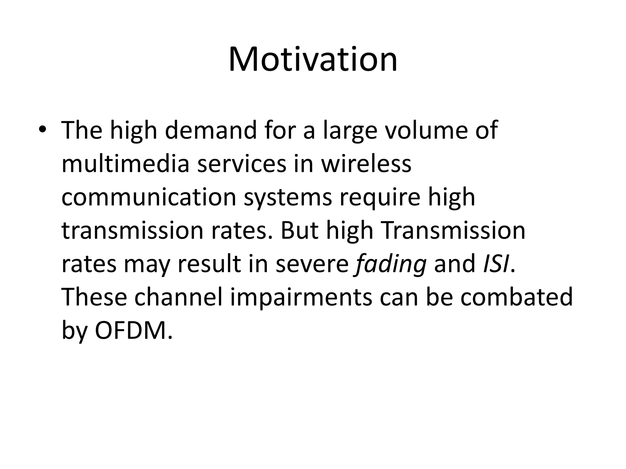
![OFDM Symbol generation
• Symbol Mapping: The high rate data streams
are first converted into parallel data of M
subchannels. The data is modulated using BPSK
before S/P conversion.
OFDM symbol is given by-
bm[k] (mapped data)
• Where m= mth data stream
• k= kth data symbol](https://image.slidesharecdn.com/progressseminar-111212005636-phpapp01/85/Progress-seminar-3-320.jpg)
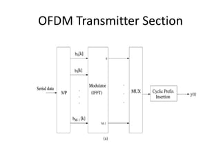
![• The autocorrelation of different transmission
paths is a zero order Bessel function that depends
on the time difference T and Doppler shift ,fd.
Autocorreletion in time domain is given by:
Φt[m]= Jo( 2πfdT)
fdT is the factor that controls how much the
channel varies betwwen two successive symbols.
Not:the above equation also indicates that the
power spectral density of the channel satisfies Jakes
model.](https://image.slidesharecdn.com/progressseminar-111212005636-phpapp01/85/Progress-seminar-17-320.jpg)

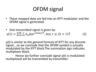
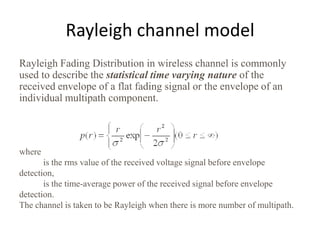
1) OFDM is used to combat channel impairments like fading and intersymbol interference that occur due to high transmission rates in wireless systems. 2) In OFDM, high rate data streams are converted to low rate parallel streams and modulated using techniques like BPSK before transmission. 3) The use of a cyclic prefix preserves orthogonality in OFDM and prevents intersymbol interference. 4) The document describes the key components of an OFDM system including the transmitter, channel model, and receiver section. It focuses on modeling the wireless channel as a Rayleigh fading channel using the Jakes model.


