The document is a summer internship report by Ronak Pandya at Essar Oil & Gas Exploration & Production Ltd., focusing on the production optimization of sucker rod pumping (SRP) wells using Prosper software. It includes acknowledgments, an introduction to artificial lift methods, details on sucker rod pumping, and an analysis of optimization techniques. The report serves as a comprehensive account of the project and outlines various artificial lift systems and their applications in the oil and gas industry.

![pg. 33Summer Internship Report-2019
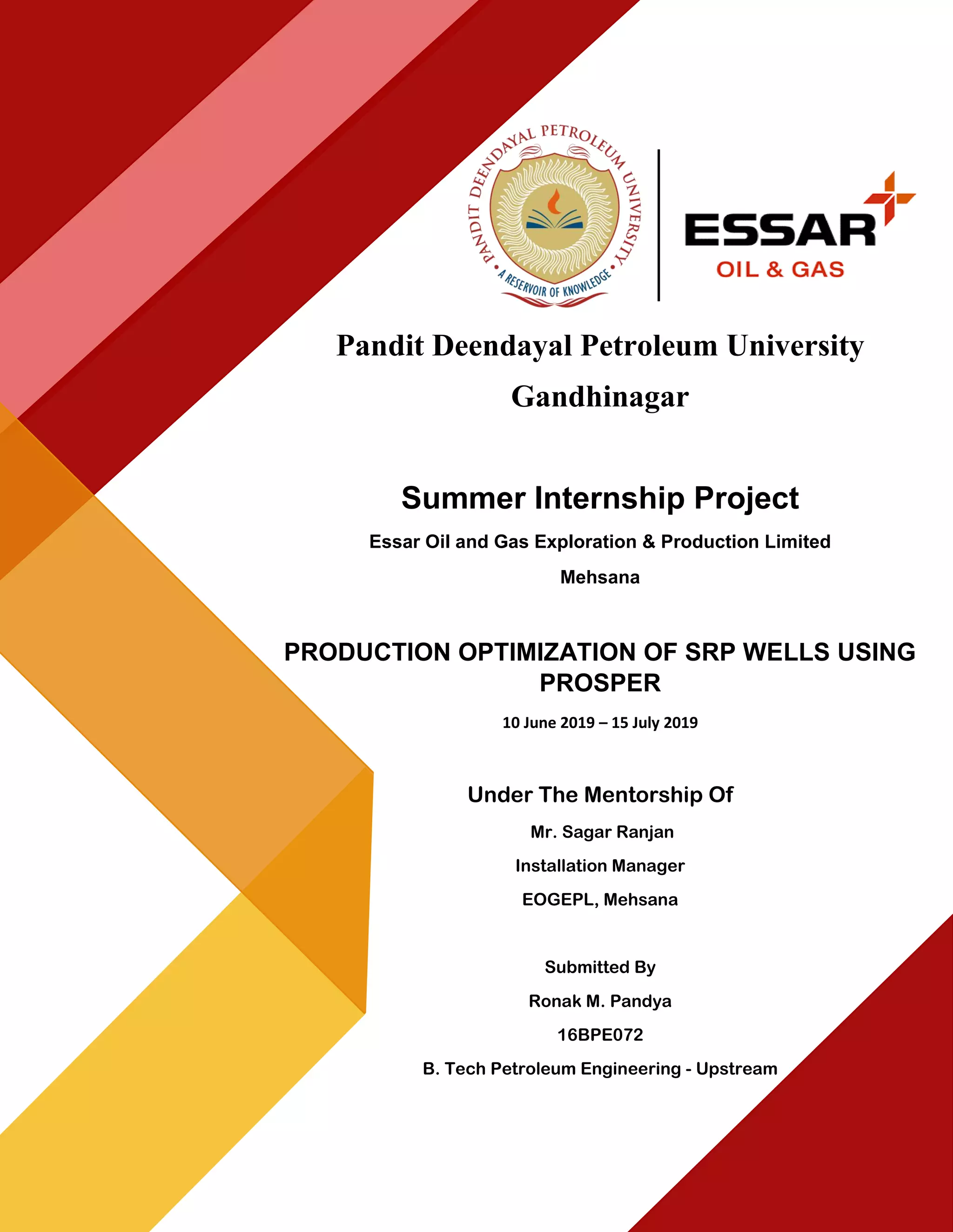
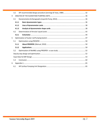
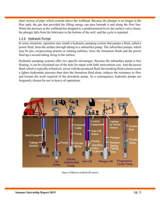
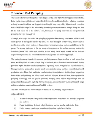
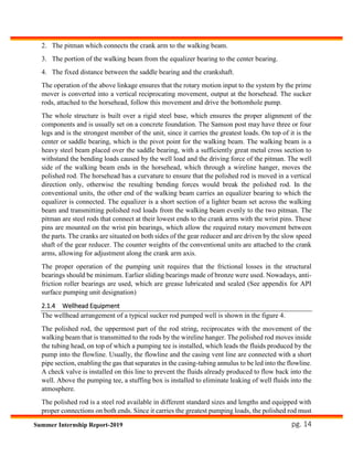
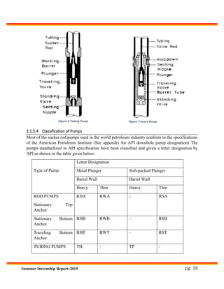
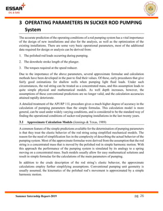
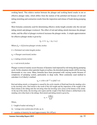
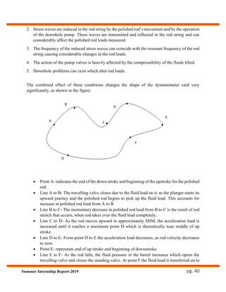
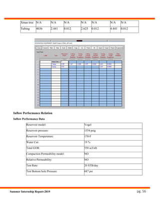
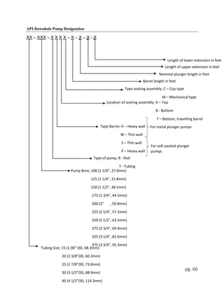
9) Unit Geometry
With these factors, the designer should be able to calculate, with some degree of reliability, the
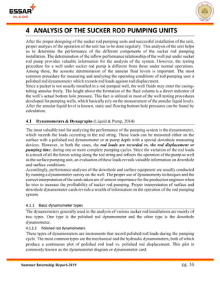
following:
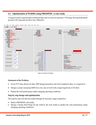
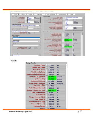
1) Plunger stroke length, 𝑆 𝑝, in
2) Plunger displacement, PD, (B/D)
3) Peak polished rod load, PPRL, lb
4) Minimum polished rod load, MPRL lb
5) Peak (Crank) torque, PT, in-lb
6) Polished rod horsepower, PRHP
7) Counter weight required, CBE, lb
These design factors are determined from the following equations
𝑆 𝑝 = [(
𝑆 𝑝
𝑆
) × 𝑆] − [ 𝐹𝑜 ×
1
𝑘 𝑡
]
When tubing is anchored, 1/kt is zero. The term 𝐹𝑜 is the gross plunger load. The value of
𝑆 𝑝
𝑆
is determined
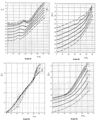
from graph 1(in Appendix)
𝐹𝑜 = 0.340 × 𝐷 𝑝
2
× 𝐷 × 𝐺
1
𝑘 𝑡
= 𝐸𝑡 × 𝐿
Where, 𝐸𝑡 is elastic constant of the tubing and may be determined from table 2(In Appendix)
The pump displacement PD is given by,
𝑃𝐷 = 0.1166𝑆 𝑝 × 𝑁 × 𝐷 𝑝
2
Peak polished rod load, PPRL is given by:
𝑃𝑃𝑅𝐿 = 𝑊𝑟𝑓 + [(
𝐹1
𝑆𝑘 𝑟
⁄ ) × 𝑆𝑘 𝑟]
Where, 𝑊𝑟𝑓 is weight of rod in fluid and is determined by:
𝑊𝑟𝑓 = 𝑊𝑟 × 𝐿 × (1 − 0.128)𝐺
The weight of rod 𝑊𝑟 is determined from table 2 (in Appendix)
The nondimensional parameter (
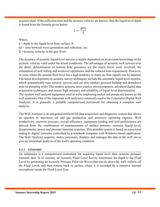
𝐹1
𝑆𝑘 𝑟
⁄ ) is determined from graph 2 (in Appendix)
The value of (
1
𝑘 𝑟
) for tapered string is given by,](https://image.slidesharecdn.com/reportronak-191003150425/85/Production-Optimization-of-SRP-wells-using-PROSPER-software-36-320.jpg)
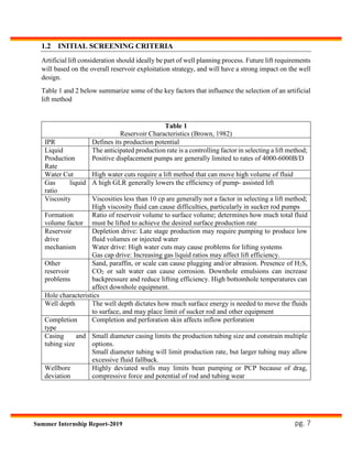
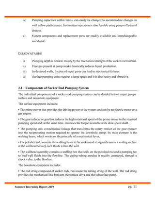
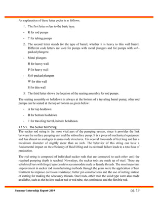
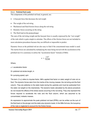
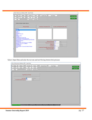
![pg. 34Summer Internship Report-2019
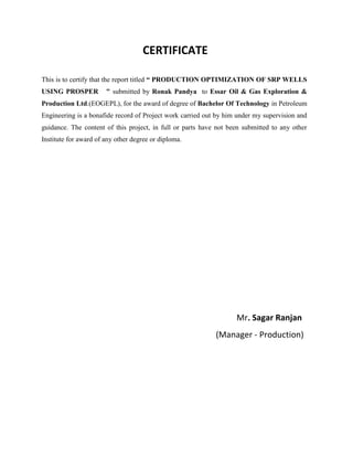
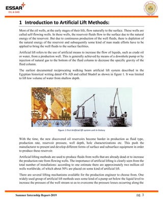
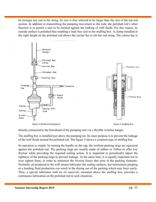
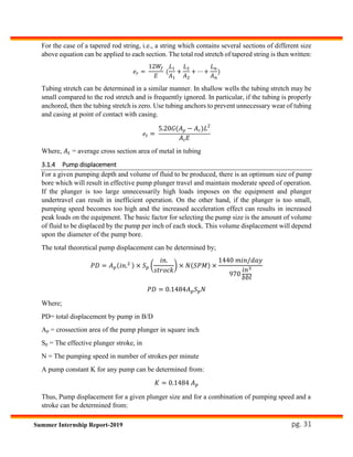
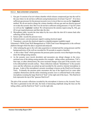
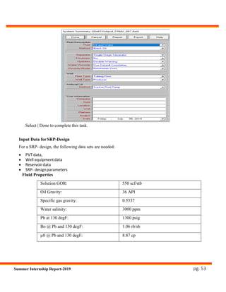
1
𝑘 𝑟
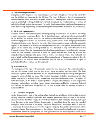
= ∑ 𝐸𝑖𝑟 × 𝐿𝑖
𝑁
𝑖=1
Where, elastic constant 𝐸𝑟 of a rod is determined from table 2 (in Appendix)
Minimum polished rod load, MPRL is given by
𝑀𝑃𝑅𝐿 = 𝑊 𝑟𝑓 − [( 𝐹2
𝑆𝑘 𝑟
⁄ ) × 𝑆𝑘 𝑟]
The parameter
(𝐹2
𝑆𝑘 𝑟
⁄ )is determined from graph 3 (in Appendix)
Peak torque PT, is given by
𝑃𝑇 = (
2𝑇
𝑆2 𝑘 𝑟
) × 𝑆𝑘 𝑟 × 𝑇𝑎 × 𝑆
2⁄
Where 𝑇𝑎 is an adjustment for peak torque for values of (
𝑊𝑟𝑓
𝑆𝑘 𝑟
⁄ ) other than 0.3. These
adjustment obtained from graph 6 (in Appendix). The value of (
2𝑇
𝑆2 𝑘 𝑟
)is obtained from graph 5.
Polished rod horse power PRHP, is given by;
𝑃𝑅𝐻𝑃 = (
𝐹3
𝑆𝑘 𝑟
⁄ ) × 𝑆𝑘 𝑟 × 𝑆 × 𝑁 × 2.53 × 10⁻⁶
The parameter (
𝐹3
𝑆𝑘 𝑟
⁄ ) is determined from graph 4.
Finally, the counterweight required is determined by,
𝐶𝐵𝐸 = 1.06(𝑊𝑟𝑓 +
𝐹𝑜
2⁄ )
In the graphs, the value of the term (
𝑁
𝑁 𝑂
) is determined by
𝑁
𝑁 𝑂
=
𝑁𝐿
2450000
The term (
𝑁
𝑁 𝑂′
) is determined from:
𝑁
𝑁 𝑂′
= (
𝑁
𝑁 𝑂
)/𝐹𝐶
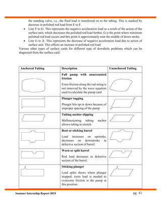
Where 𝐹𝐶 (frequency factor) is a constant of proportionality which depends upon the rod string
design. The dimensionless pumping speed (
𝑁
𝑁 𝑂′
) is an important index of the behavior of the rod
string. The frequency factor can be determined from table 2 (in Appendix)](https://image.slidesharecdn.com/reportronak-191003150425/85/Production-Optimization-of-SRP-wells-using-PROSPER-software-37-320.jpg)
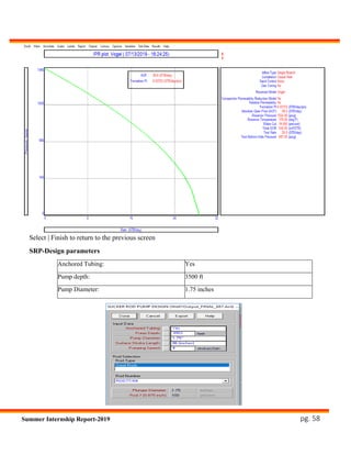
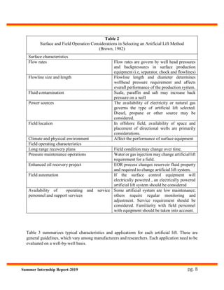
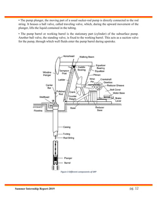
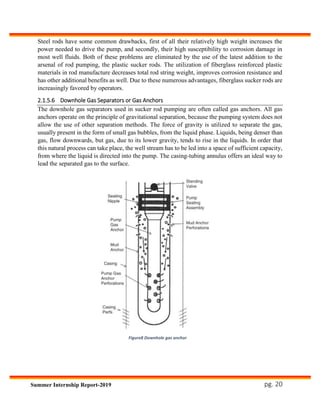
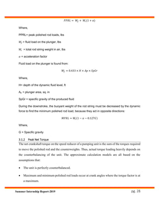
![pg. 68
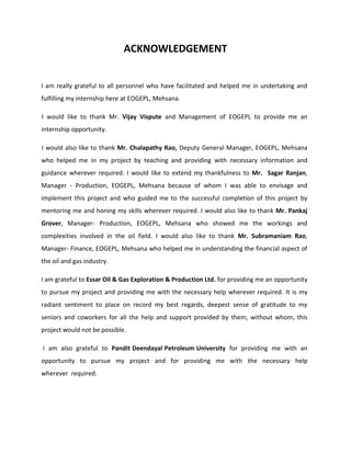
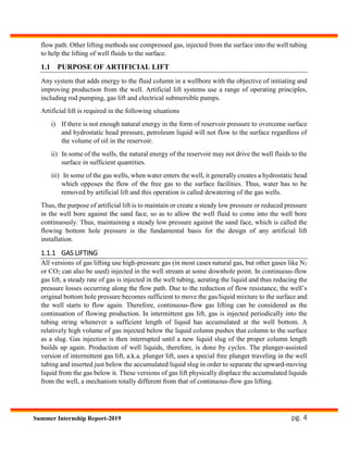
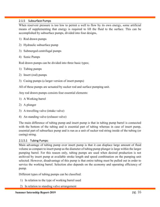
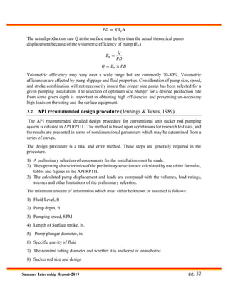
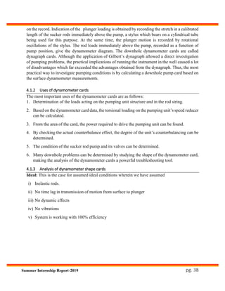
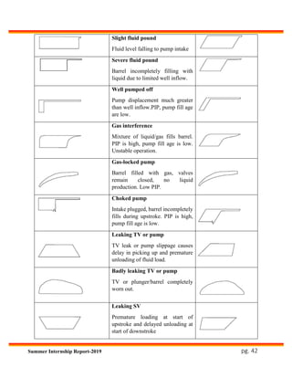
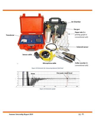
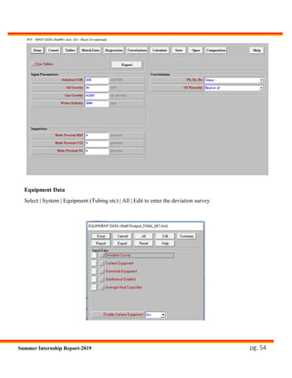
Reference of all graph: API RP 11L Recommended practice for design calculations for
sucker rod pumping systems (conventional units). 4th ed. Washington, D.C: American
Petroleum Institute; 1988.
Tubing size Outside
diameter
Inside
diameter
Metal area Elastic
constant
in in in Sq.in. in /(lb ft)
1.9 1.900 1.610 0.800 0.500 E-6
2 3/8 2.375 1.995 1.304 0.307 E-6
2 7/8 2.875 2.441 1.812 0.221 E-6
3 1/2 3.500 2.992 2.590 0.154 E-6
4 4.000 3.476 3.077 0.130 E-6
4 1/2 4.500 3.958 3.601 0.111 E-6
Table 1 Basic data of API tubing [1]
Graph 05 Graph 06](https://image.slidesharecdn.com/reportronak-191003150425/85/Production-Optimization-of-SRP-wells-using-PROSPER-software-71-320.jpg)
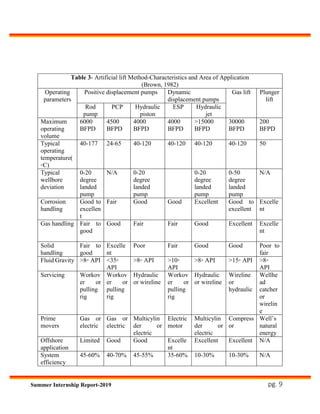
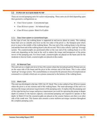
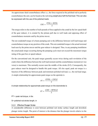
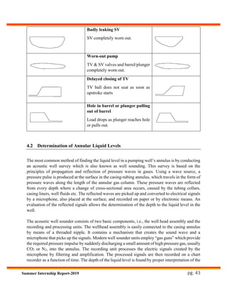
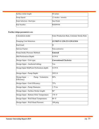
![pg. 69
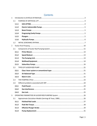
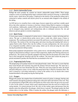
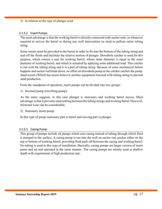
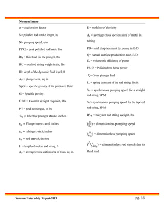
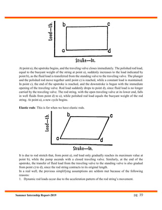
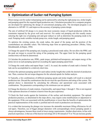
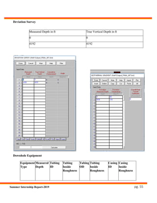
Table 2 Rod and Pump data [1]](https://image.slidesharecdn.com/reportronak-191003150425/85/Production-Optimization-of-SRP-wells-using-PROSPER-software-72-320.jpg)
![pg. 70
Table 3 Rod and Pump data (Cont.) [1]](https://image.slidesharecdn.com/reportronak-191003150425/85/Production-Optimization-of-SRP-wells-using-PROSPER-software-73-320.jpg)


![[Deck] What's New in Spark-Iceberg Integration via DSV2.pptx](https://cdn.slidesharecdn.com/ss_thumbnails/deckwhatsnewinspark-icebergintegrationviadsv2-260210005337-25955b12-thumbnail.jpg?width=640&height=640&fit=bounds)


