4- 3
10/12/25
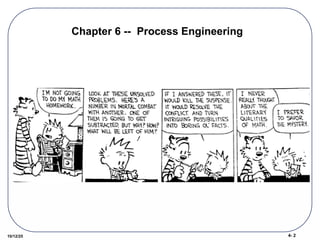
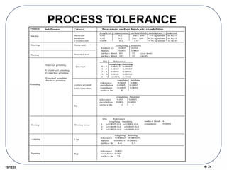
The EngineeringProcess
Stock Material Processes Finished part
Design
specifications
Process planning
Process
capability
Inspection
Need to understand the process capabilities.
4.
4- 4
10/12/25
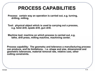
PROCESS CAPABILITIES
Process:certain way an operation is carried out, e.g. turning,
drilling, milling.
Tool: physical object which is used to carrying out a process,
e.g. twist drill, spade drill, gun drill.
Machine tool: machine on which process is carried out, e.g.
lathe, drill press, milling machine, machining center.
Process capability: The geometry and tolerance a manufacturing process
can produce, and its limitations, . i.e. shape and size, dimensional and
geometric tolerances, material removal rate, relative cost, other
cutting constraints.
5.
4- 5
10/12/25
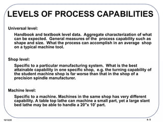
LEVELS OFPROCESS CAPABILITIES
Universal level:
Handbook and textbook level data. Aggregate characterization of what
can be expected. General measures of the process capability such as
shape and size. What the process can accomplish in an average shop
on a typical machine tool.
Shop level:
Specific to a particular manufacturing system. What is the best
attainable capability in one specific shop, e.g. the turning capability of
the student machine shop is far worse than that in the shop of a
precision spindle manufacturer.
Machine level:
Specific to a machine. Machines in the same shop has very different
capability. A table top lathe can machine a small part, yet a large slant
bed lathe may be able to handle a 20"x 10' part.
6.
4- 6
10/12/25
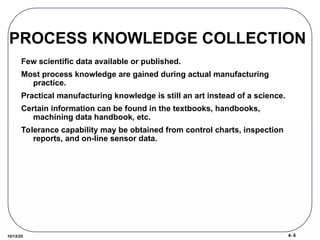
PROCESS KNOWLEDGECOLLECTION
Few scientific data available or published.
Most process knowledge are gained during actual manufacturing
practice.
Practical manufacturing knowledge is still an art instead of a science.
Certain information can be found in the textbooks, handbooks,
machining data handbook, etc.
Tolerance capability may be obtained from control charts, inspection
reports, and on-line sensor data.
7.
4- 7
10/12/25
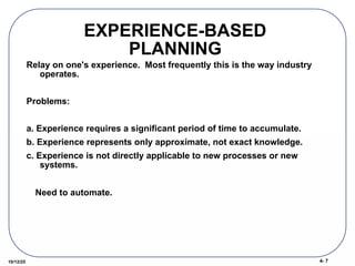
EXPERIENCE-BASED
PLANNING
Relay onone's experience. Most frequently this is the way industry
operates.
Problems:
a. Experience requires a significant period of time to accumulate.
b. Experience represents only approximate, not exact knowledge.
c. Experience is not directly applicable to new processes or new
systems.
Need to automate.
8.
4- 8
10/12/25
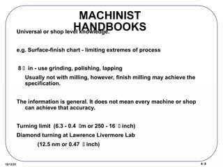
MACHINIST
HANDBOOKS
Universal orshop level knowledge.
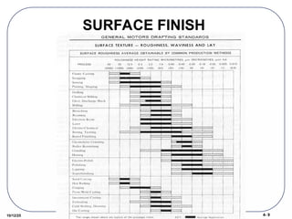
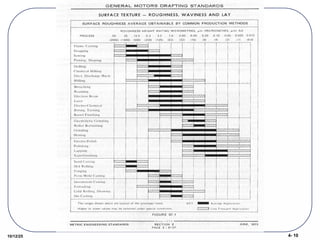
e.g. Surface-finish chart - limiting extremes of process
8 in - use grinding, polishing, lapping
Usually not with milling, however, finish milling may achieve the
specification.
The information is general. It does not mean every machine or shop
can achieve that accuracy.
Turning limit (6.3 - 0.4 m or 250 - 16 inch)
Diamond turning at Lawrence Livermore Lab
(12.5 nm or 0.47 inch)
4- 12
10/12/25
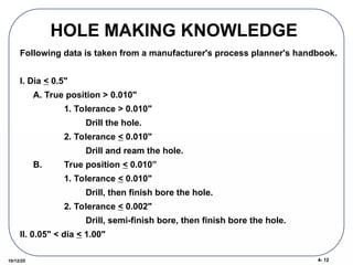
HOLE MAKINGKNOWLEDGE
Following data is taken from a manufacturer's process planner's handbook.
I. Dia < 0.5"
A. True position > 0.010"
1. Tolerance > 0.010"
Drill the hole.
2. Tolerance < 0.010"
Drill and ream the hole.
B. True position < 0.010”
1. Tolerance < 0.010"
Drill, then finish bore the hole.
2. Tolerance < 0.002"
Drill, semi-finish bore, then finish bore the hole.
II. 0.05" < dia < 1.00"
13.
4- 13
10/12/25
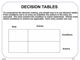
DECISION TABLES
Tocomputerize the decision making, one simple way is to use decision tables.
If the conditions set in an entry are satisfied, the actions in the entry are
executed. The stub contains the condition or action statements. Entries mark
which conditions or actions are applicable. Each entry contain one rule.
Conditions
Actions
Stub Entries
14.
4- 14
10/12/25
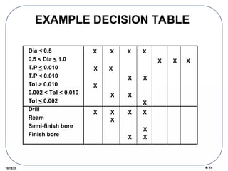
EXAMPLE DECISIONTABLE
Dia < 0.5
0.5 < Dia < 1.0
T.P < 0.010
T.P < 0.010
Tol > 0.010
0.002 < Tol < 0.010
Tol < 0.002
Drill
Ream
Semi-finish bore
Finish bore
X X X X
X
X
X
X X
X
X
X
X
X
X
X
X X X
X
X
X X
15.
4- 15
10/12/25
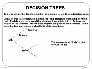
DECISION TREES
Node
Branch
Tocomputerize the decision making, one simple way is to use decision trees.
Decision tree is a graph with a single root and branches emanating from the
root. Each branch has a condition statement associate with it. Actions are
written at the terminal. Probabilities may be assigned to the branches. In this
case, the tree represents probabilistic state transitions.
Root
terminal
The node may be "AND" nodes
or "OR" nodes.
16.
4- 16
10/12/25
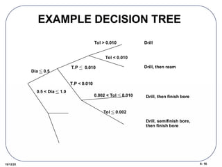
EXAMPLE DECISIONTREE
Dia < 0.5
0.5 < Dia < 1.0
T.P < 0.010
T.P < 0.010
Tol > 0.010
Tol < 0.010
0.002 < Tol < 0.010
Tol < 0.002
Drill
Drill, then ream
Drill, then finish bore
Drill, semifinish bore,
then finish bore
4- 26
10/12/25
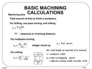
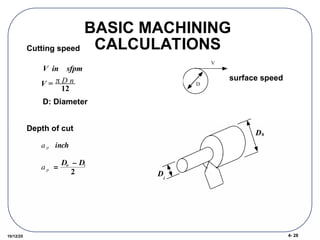
BASIC MACHINING
CALCULATIONS
tm= L + L
v f
Machining time
Total amount of time to finish a workpiece.
For drilling, one pass turning, and milling:
L : clearance or overhang distance.
For multipass turning
n p =
Do – Di
2 a p
+
integer round up
For milling
n p = h
a p
+
w
D
+
n p : # of passes
h : total height of material to be removed
w : workpiece width
: cutter overlapping factor
= effective cutting width / tool dia 1.0
27.
4- 27
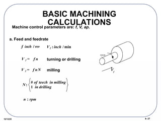
10/12/25
BASIC MACHINING
CALCULATIONS
Machinecontrol parameters are: f, V, ap.
a. Feed and feedrate
f
: inch / rev
turning or drilling
milling
rp m
N:
# of teech in milling
1 in drilling
n : rpm
V f = f nN
V f = f n
V f : inch / min
Vf
4- 29
10/12/25
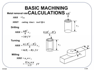
BASIC MACHINING
CALCULATIONS
Metalremoval rate
MRR cutting time tool life
MRR in3
min
in3
min
Drilling
Turning
Milling
W
v f
a p
MRR = D
2
4
v f
= 3D f V
MRR =
( D
2
o – D
2
i)
4
v f
= 6(Do – Di ) f V
v f
(D
2
o –D
2
i)
4
MRR = a p w v f
=
12 a p w n
D
f V
D
2
4
v f
30.
4- 30
10/12/25
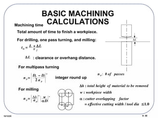
BASIC MACHINING
CALCULATIONS
tm= L + L
v f
Machining time
Total amount of time to finish a workpiece.
For drilling, one pass turning, and milling:
L : clearance or overhang distance.
For multipass turning
n p =
Do – Di
2 a p
+
integer round up
For milling
n p = h
a p
+
w
D
+
n p : # of passes
h : total height of material to be removed
w : workpiece width
: cutter overlapping factor
= effective cutting width / tool dia 1.0
L
31.
4- 31
10/12/25
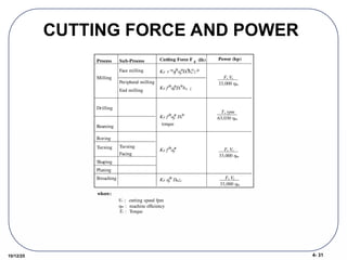
CUTTING FORCEAND POWER
Process Sub-Process
Milling
End milling
Peripheral milling
Face milling
Drilling
Reaming
Boring
Shaping
Planing
Broaching
Turning
Facing
Turning
Cutting Force F Power (hp)
KF fF
ap
F
Dt
F
bw z
KF v Faf
F
ap
F
bw
F
zF
Dt
F
KF f
F
ap
F
KF fF
ap
F
Dt
F
KF ap
F
Dmzc
c (lb)
Fc Vc
33,000 m
Fc Vc
33,000 m
Fc Vc
33,000 m
Ts rpm
63,030 m
where:
Vc :: cutting speed fpm
m : machine efficiency
Ts : Torque
torque
32.
4- 32
10/12/25
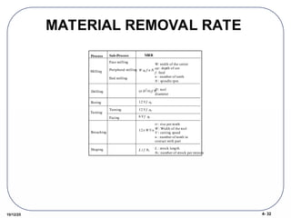
MATERIAL REMOVALRATE
Process Sub-Process
Milling
End milling
Peripheral milling
Face milling
Drilling
Boring
Shaping
Broaching
Turning
W: width of the cutter
ap : depth of cut
f : feed
n : number of teeth
N : spindle rpm
D : tool
diameter
tr : rise per tooth
W : Width of the tool
V : cutting speed
n : number of tooth in
contact with part
12 tr W V n
( D
2
/4)f N
12 V f ap
12 V f ap
Facing
Turning
6 V f ap
L t f Ns
L : strock length
Ns: number of strock per minute
W ap f n N
MRR
33.
4- 33
10/12/25
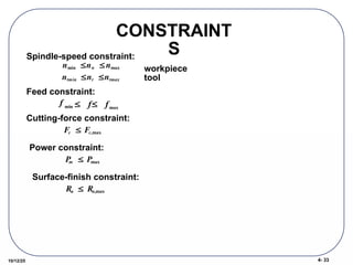
CONSTRAINT
S
nmin nwnmax
ntmin nt ntmax
Fc Fc,max
Spindle-speed constraint:
workpiece
tool
Feed constraint:
Cutting-force constraint:
P
m Pmax
Power constraint:
Ra Ra,max
Surface-finish constraint:
f min f fmax
34.
4- 34
10/12/25
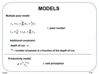
MODELS
Multiple passmodel
t pr th + (ti
m
i =1
n p
+
ti
m
t
tt
)
c pr
cb
nb
+ cmth + ci
pr
i = 1
n p
i : pass number
Additional constraint:
depth of cut
: number of passes is a function of the depth of cut.
a p
n p
Productivity model:
p
r
s – c pr
t pr
s: sale price/piece


![[Deck] What's New in Spark-Iceberg Integration via DSV2.pptx](https://cdn.slidesharecdn.com/ss_thumbnails/deckwhatsnewinspark-icebergintegrationviadsv2-260210005337-25955b12-thumbnail.jpg?width=640&height=640&fit=bounds)


