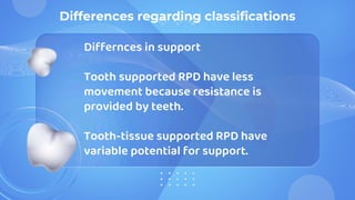
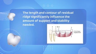
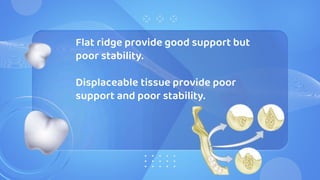
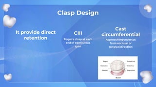
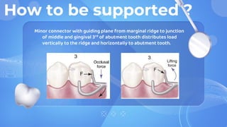
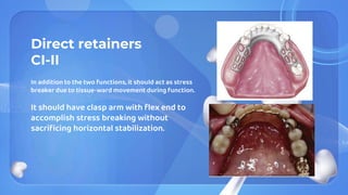
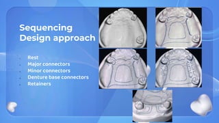
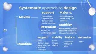
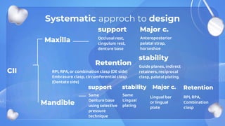
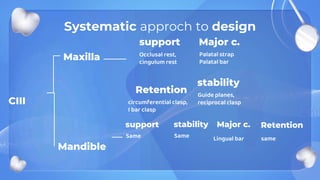
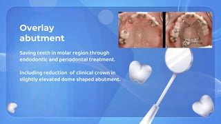
This document discusses principles of removable partial denture (RPD) design, including Kennedy classification systems for different clinical situations, considerations for support and retention, and a systematic approach to RPD design. Key points covered include differentiating tooth-supported versus tissue-supported designs, using minor connectors along guiding planes for optimal stress distribution, and employing techniques like indirect retainers and reciprocal clasps to restrict horizontal movement. The summary concludes that RPD design should be systematically developed based on factors like the location of support and how retention is achieved.
3. Class I Bilateral edentulous areas located posterior to natural teeth
Class II Unilateral edentulous area located posterior to natural teeth
Class III Unilateral edentulous area with natural teeth remaining both anterior and posterior to
it
Class IV Single but bilateral –crossing the midline- edentulous area located anterior to the
remaining natural teeth
Kennedy classification
4.
5. Differnces in support
Tooth supported RPD have less
movement because resistance is
provided by teeth.
Tooth-tissue supported RPD have
variable potential for support.
Differences regarding classifications
6.
7. CI and CII primary support from tissue
underlying base, and secondary
support from abutment teeth.
CIII all its support from abutment
teeth.
8. CI and CII require dual selective
pressure impression, while CIII can be
done in single stage impression.
Indirect retainer is needed for CI and
CII due to fulcrum effect.
9. The length and contour of residual
ridge significantly influence the
amount of support and stability
needed.
10. Flat ridge provide good support but
poor stability.
Displaceable tissue provide poor
support and poor stability.
11. Approaching undercut
from occlusal or
gingival direction
Cast
circumferential
Clasp Design
It provide direct
retention
CIII
Require clasp at each
end of edentulous
span
12. Clasp Design
CI and CII
The direct retainer not only should resist vertical dislodging forces but also should be able
to flex sufficiently to dissipate the stresses that torquing on terminal abutment from
leverage effect.
Mesial rest seat reduce leverage effect by changing fulcrum point.
Wrought wire (WW) provide more flex in all directions than cast half round (cross-section)
arm, also bar clasp type can be used.
Use of combination clasp (circumferential arm + rigid reciprocating arm) is indicated, where
only MB undercut exists or gross tissue undercut cervical and buccal to abutment tooth.
13. Essentials of RPD Design
How to be
supported ?
Systematic
development of
design
How to be
retained ?
Connecting
units
Outline and join edentulous
area to other components
14. How to be
supported ?
01
Ideal rest location for CIII is on abutment
adjacent to each edentulous space.
Consider: periodontal health, crown and root
morphologies, crown to root ratio,
location of tooth in the arch, location of
tooth to other supporting units.
CI and CII need same consideration with
adding evaluation of residual ridge
15. How to be supported ?
Maximal contact of proximal plate minor connector with guiding
plane produces more horizontal distribution of stress to
abutment teeth.
16. How to be supported ?
Minimal contact or disengagement of minor connector with guiding
plane allows rotation around fulcrum on MO rest producing more
vertical stress to ridge.
17. How to be supported ?
Minor connector with guiding plane from marginal ridge to junction
of middle and gingival 3rd of abutment tooth distributes load
vertically to the ridge and horizontally to abutment tooth.
21. Outline and join
the edentulous
area to already
established
design
components
05
22. framework parts
Minor
connectors
Join major connector to
other parts
Direct
retainers
Retention and resistance
Major
connectors
Connect parts on one
side to the opposite
Guiding plane and
rest seats
Direct prosthesis during removal
and placement and resist
tissueward movement
Indirect
retainers
Restrict movement of
base away from tissue
1 2 3 4 5
23. Direct retainers
CIII
Two functions:
1. Retain prosthesis against dislodging forces
without damage to abutment teeth.
2. Aid in resisting any tendency of denture to be
displaced in a horizontal plane.
Intracoronal frictional retainers are ideal.
circumferential and bar type extracoronal
retainers are effective
24. Direct retainers
CI-II
In addition to the two functions, it should act as stress
breaker due to tissue-ward movement during function.
It should have clasp arm with flex end to
accomplish stress breaking without
sacrificing horizontal stabilization.
25. Guiding plane
Two or more parallel vertical surfaces of
abutment teeth to direct a prosthesis
during placement and removal.
Preferred to be more than two abutments
on wide separate positions.
27. Indirect retainers
Needed only in class I and II where distal
extension exists.
Should be as anterior as possible from
fulcrum line.
Cannot function effectively on inclined
tooth or single weak incisor.
29. Systematic approch to design
CI
Mandible
Maxilla
support
Occlusal rest,
cingulum rest,
denture base
palatal coverage
Major c.
Anteroposterior
palatal strap, full
coverage
stability
Guide planes, indirect
retainers, reciprocal
clasp, palatal plating.
Retention
RPI, RPA, or
combination clasp
support
Same
Denture base
using selective
pressure
technique
stability
Same
Lingual
plating
Major c.
Lingual bar
or lingual
plate
Retention
Same
30. Systematic approch to design
CII
Mandible
Maxilla
support
Occlusal rest,
cingulum rest,
denture base
Major c.
Anteroposterior
palatal strap,
horseshoe
stability
Guide planes, indirect
retainers, reciprocal
clasp, palatal plating.
Retention
RPI, RPA, or combination clasp (DE side)
Embrasure clasp, circumferential clasp
(Dentate side)
support
Same
Denture base
using selective
pressure
technique
stability
Same
Lingual
plating
Major c.
Lingual bar
or lingual
plate
Retention
RPI, RPA,
Combination
clasp
31. Systematic approch to design
CIII
Mandible
Maxilla
support
Occlusal rest,
cingulum rest
Major c.
Palatal strap
Palatal bar
stability
Guide planes,
reciprocal clasp
Retention
circumferential clasp,
I bar clasp
support
Same
stability
Same
Major c.
Lingual bar
Retention
same
32. Implant considerations in RPD design
aim to reduce distal extension
movement and enhancing support if
placed at distal most tooth position
Additional considerations influencing design
34. Splint bar
When several missing anterior teeth with
length span that cannot be replaced with
FPD
+ large amount of residual ridge defect
Complete assembly of abutment and bar
are cemented then impression is done.
Framework extend to cover upon bar.
36. Overlay
abutment
Saving teeth in molar region through
endodontic and periodontal treatment.
Including reduction of clinical crown in
slightly elevated dome shaped abutment.
38. Conclusions
The design of the partial denture framework should be
systematically developed and outlined on an accurate
diagnostic cast based on the following prosthesis
concepts: where the prosthesis is supported, how the
support is connected, how the prosthesis is retained, how
the retention and support are connected, and how
edentulous base support is connected.
Other factors affecting support:
-opposing dentition.
-occlusion.
-broad dissipation of occlusal relationship at MI
Tissue distortion over edentulous ridge 500 um under 4 N, whereas abutment teeth show only 20 um under same load.
The longer the area covered by denture base the greater the leverage.
It can be addressed with dental implant
Tissue-ward movement affected by: quality of soft tissue, accuracy of denture base, and total occlusal load applied.
Quality of ridge, extent of edentulous space covered by denture base, type and accuracy of impression, accuracy of base, design characteristics of components of framework, and anticipated load.
For successful clasp design:
Avoid direct transmission of tipping or torquing forces to abutment.
Accommodate basic principles of clasp design.
Provide retention against reasonable dislodging forces.
Compatible with undercut location, tissue contour, and esthetic desires of the patient.
Cast clasp used for tooth supported side while wrought wire for distal extension side to reduce torque.
In case of severe tissue undercut or only MB undercut exist then a combination of retentive arm with tapered wrought wire is used.
Function:
Provide one path of placement and removal.
To ensure the intended action of reciprocal, stabilizing, and retentive components.
To eliminate gross food traps between abutment and other components.
Inevitable torquing forces.
And implants
Act as guide plane
Aid in resisting horizontal rotation.
Should be lingually positioned to allow arrangement of teeth.
Metal or nylon clips fit the bar which is retained within metal housing or embedded by spurs or loops into resin base.