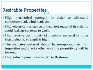
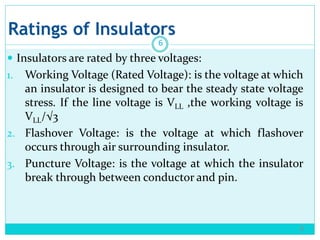
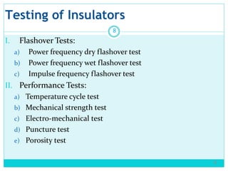
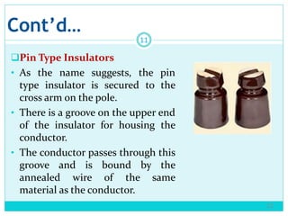
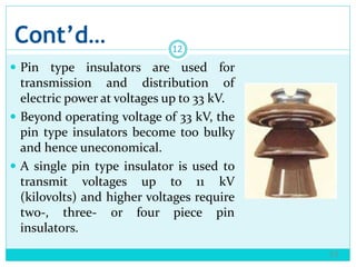
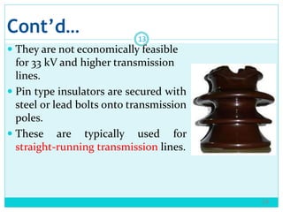
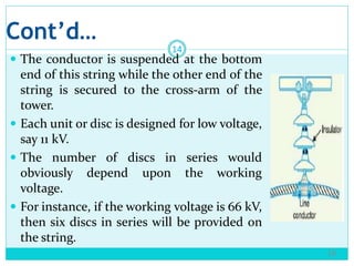
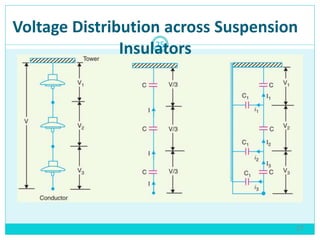
Introduction to Power
Systems(ECEG-3176)
Addis Ababa University
Addis Ababa Institute of Technology (AAiT)
School of Electrical & Computer Engineering
Instructor: Awraris Getachew
Chapter 6
Insulators
2
1
Cont’d…
Definition
 An insulator is a device intended to give flexible or rigid
support to electric conductors or equipment and to
insulate these conductors or equipment from ground or
from other conductors or equipment.
 Overhead transmission lines are supported on the towers.
Since towers are at ground potential, the lines must be
insulated from the tower structure.
3
3
Desirable Properties
 High mechanical strength in order to withstand
conductor load, wind load, etc.
 High electrical resistance of insulator material in order to
avoid leakage currents to earth.
 High relative permittivity of insulator material in order
that dielectric strength is high.
 The insulator material should be non-pores, free from
impurities and cracks other wise the permittivity will be
lowered.
 High ratio of puncture strength to flashover.
4
4
Materials
 Porcelain
 Toughened Glass
 Polymeric composite
 Choice of insulator material is governed by availability,
price and ease of maintenance.
 Porcelain is most widely used insulator material as it is
cheap.
5
5
Ratings of Insulators
 Insulators are rated by three voltages:
1. Working Voltage (Rated Voltage): is the voltage at which
an insulator is designed to bear the steady state voltage
stress. If the line voltage is VLL ,the working voltage is
VLL/√3
2. Flashover Voltage: is the voltage at which flashover
occurs through air surrounding insulator.
3. Puncture Voltage: is the voltage at which the insulator
break through between conductor and pin.
6
6
Cont’d…
7
Flash Over around insulators
Cont’d…
 Flashover voltage is higher than working voltage and less
than the puncture voltage of the insulator.
 A safety factor is defined as a ratio of flashover voltage to
working voltage.
 Safety factor = Flashover Voltage/Working Voltage
8
7
Testing of Insulators
I. Flashover Tests:
a) Power frequency dry flashover test
b) Power frequency wet flashover test
c) Impulse frequency flashover test
II. Performance Tests:
a) Temperature cycle test
b) Mechanical strength test
c) Electro-mechanical test
d) Puncture test
e) Porosity test
9
8
Cont’d…
III. Routine Tests:
a) Corrosion test
b) Proof-load test
10
9
Types of Insulators
11
10
 There are several types of insulators but the most
commonly used are:
pin type
suspension type
strain insulator and
shackle insulator
Cont’d…
Pin Type Insulators
• As the name suggests, the pin
type insulator is secured to the
cross arm on the pole.
• There is a groove on the upper end
of the insulator for housing the
conductor.
• The conductor passes through this
groove and is bound by the
annealed wire of the same
material as the conductor.
12
11
Cont’d…
 Pin type insulators are used for
transmission and distribution of
electric power at voltages up to 33 kV.
 Beyond operating voltage of 33 kV, the
pin type insulators become too bulky
and hence uneconomical.
 A single pin type insulator is used to
transmit voltages up to 11 kV
(kilovolts) and higher voltages require
two-, three- or four piece pin
insulators.
13
12
Cont’d…
 They are not economically feasible
for 33 kV and higher transmission
lines.
 Pin type insulators are secured with
steel or lead bolts onto transmission
poles.
 These are typically used for
straight-running transmission lines.
14
13
Cont’d…
Suspension Type
Insulators
 For high voltages (>33
kV), it is a usual practice
to use suspension type
insulators consist of a
number of porcelain
discs connected in series
by metal links in the
form of a string
15
13
Cont’d…
16
14
 The conductor is suspended at the bottom
end of this string while the other end of the
string is secured to the cross-arm of the
tower.
 Each unit or disc is designed for low voltage,
say 11 kV.
 The number of discs in series would
obviously depend upon the working
voltage.
 For instance, if the working voltage is 66 kV,
then six discs in series will be provided on
the string.
Cont’d…
Advantages of suspension type insulators
1. Suspension type insulators are cheaper than pin type
insulators for voltages beyond 33 KV.
2. Each unit or disc of suspension type insulator is
designed for low voltage, usually 11 kV. Depending upon
the working voltage, the desired number of discs can be
connected in series.
17
15
Cont’d…
3. If any one disc is damaged, the whole string does not
become useless because the damaged disc can be
replaced by the sound one.
4. The suspension arrangement provides greater flexibility
to the line. The connection at the cross arm is such that
insulator string is free to swing in any direction and can
take up the position where mechanical stresses are
minimum.
18
16
Cont’d…
19
17
5. In case of increased demand on the transmission line,
it is found more satisfactory to supply the greater
demand by raising the line voltage than to provide
another set of conductors. The additional insulation
required for the raised voltage can be easily obtained
in the suspension arrangement by adding the desired
number of discs.
6. The suspension type insulators are generally used
with steel towers. As the conductors run below the
earthed cross-arm of the tower, therefore, this
arrangement provides partial protection from
lightning
Cont’d…
Strain Type Insulators
 When there is a dead end of the line or there is corner or
sharp curve, the line is subjected to greater tension.
 In order to relieve the line of excessive tension, strain
insulators are used.
 For low voltage lines (< 11 kV), shackle insulators are used
as strain insulators.
20
18
Cont’d…
21
19
Cont’d…
 However, for the high voltage transmission lines, strain
insulator consists of an assembly of suspension
insulators.
 The discs of strain insulators are used in the vertical
plane. When the tension in lines is exceedingly high, at
long river spans, two or more strings are used in
parallel.
22
20
Cont’d…
23
21
 Strain type insulators are horizontally suspended
suspension insulators.
 They are used to handle mechanical stresses and take the
pressure off a conductor at the end of a transmission line,
at a sharp corner or curve or over long river crossings.
 Strain insulators are typically used for higher voltage
transmissions.
Cont’d…
Shackle Type Insulators
 Shackle type insulators, similar to strain type insulators,
are used on sharp curves, end poles and in section poles.
24
22
Cont’d…
 These insulators are single, round porcelain parts that are
mounted horizontally or vertically.
 In early days, the shackle insulators were used as strain
insulators.
 But now a days, they are frequently used for low voltage
distribution lines.
 They can be directly fixed to the pole with a bolt or to the
cross arm.
25
23
Cont’d…
26
24
Voltage Distribution across Suspension
Insulators
27
25
Cont’d…
 The following points may be noted regarding the
potential distribution over a string of suspension
insulators:
i. The voltage impressed on a string of suspension
insulators does not distribute itself uniformly across
the individual discs due to the presence of shunt
capacitance.
ii. The disc nearest to the conductor has maximum voltage
across it. As we move towards the cross-arm, the
voltage across each disc goes on decreasing.
28
26
Cont’d…
iii. The disc nearest to the conductor is under maximum
electrical stress and is likely to be punctured.
Therefore, means must be provided to equalize the
potential across each unit.
iv. If the voltage impressed across the string is dc, then
voltage across each unit would be the same. It is
because insulator capacitances are ineffective for dc.
29
26
Cont’d…
String Efficiency
 Where n is the total number of discs in the string.
 The greater the string efficiency, the more uniform is the
voltage distribution.
30
26
Cont’d…
 Mathematical Expression
 Let:
 3-disc string
 Self (mutual) capacitance = C
 Shunt capacitance (C1) = KC (fraction of C)
31
26
Cont’d…
32
Cont’d…
33
 Voltage between conductor and earth (tower):
Cont’d…
● If the number of units/insulator discs is increased ,it is
more difficult to calculate the potential across each unit
by using the above technique.
● Therefore the potential across the 𝑖𝑡ℎ unit from the
bottom is given by the empirical formula as
𝑉𝑖 =
𝑉 ∗ 2 sinh 0.5 𝐾 cosh 𝑛 − 𝑖 + 0.5 𝐾
sinh 𝑛 𝐾
Where 𝑛 𝑖𝑠 𝑡ℎ𝑒 𝑛𝑢𝑚𝑏𝑒𝑟 𝑜𝑓 𝑖𝑛𝑠𝑢𝑙𝑎𝑡𝑜𝑟 𝑑𝑖𝑠𝑐𝑠
𝐾 𝑖𝑠 𝑡ℎ𝑒 𝑟𝑎𝑡𝑖𝑜 𝑜𝑓 𝑠ℎ𝑢𝑛𝑡 𝑡𝑜 𝑚𝑢𝑡𝑢𝑎𝑙 𝑐𝑎𝑝𝑎𝑐𝑖𝑡𝑎𝑛𝑐𝑒
𝑉 𝑖𝑠 𝑡ℎ𝑒 𝑣𝑜𝑙𝑡𝑎𝑔𝑒 𝑎𝑐𝑟𝑜𝑠𝑠 𝑡ℎ𝑒 𝑠𝑡𝑟𝑖𝑛𝑔(𝑝ℎ𝑎𝑠𝑒 𝑣𝑜𝑙𝑡𝑎𝑔𝑒)
34
Methods to Improve String Efficiency
35
1. By using longer cross arms (Reducing the value of K)
2. By grading the insulator (Capacitance grading)
3. By using a guard ring
Reference/Exercise
 Electric Power Transmission and Distribution: By S. Sivanagaraju
 Principles of power systems: By V.K. Metha

Chapter 6N (2).pptx

  • 1.
    Introduction to Power Systems(ECEG-3176) AddisAbaba University Addis Ababa Institute of Technology (AAiT) School of Electrical & Computer Engineering Instructor: Awraris Getachew
  • 2.
  • 3.
    Cont’d… Definition  An insulatoris a device intended to give flexible or rigid support to electric conductors or equipment and to insulate these conductors or equipment from ground or from other conductors or equipment.  Overhead transmission lines are supported on the towers. Since towers are at ground potential, the lines must be insulated from the tower structure. 3 3
  • 4.
    Desirable Properties  Highmechanical strength in order to withstand conductor load, wind load, etc.  High electrical resistance of insulator material in order to avoid leakage currents to earth.  High relative permittivity of insulator material in order that dielectric strength is high.  The insulator material should be non-pores, free from impurities and cracks other wise the permittivity will be lowered.  High ratio of puncture strength to flashover. 4 4
  • 5.
    Materials  Porcelain  ToughenedGlass  Polymeric composite  Choice of insulator material is governed by availability, price and ease of maintenance.  Porcelain is most widely used insulator material as it is cheap. 5 5
  • 6.
    Ratings of Insulators Insulators are rated by three voltages: 1. Working Voltage (Rated Voltage): is the voltage at which an insulator is designed to bear the steady state voltage stress. If the line voltage is VLL ,the working voltage is VLL/√3 2. Flashover Voltage: is the voltage at which flashover occurs through air surrounding insulator. 3. Puncture Voltage: is the voltage at which the insulator break through between conductor and pin. 6 6
  • 7.
  • 8.
    Cont’d…  Flashover voltageis higher than working voltage and less than the puncture voltage of the insulator.  A safety factor is defined as a ratio of flashover voltage to working voltage.  Safety factor = Flashover Voltage/Working Voltage 8 7
  • 9.
    Testing of Insulators I.Flashover Tests: a) Power frequency dry flashover test b) Power frequency wet flashover test c) Impulse frequency flashover test II. Performance Tests: a) Temperature cycle test b) Mechanical strength test c) Electro-mechanical test d) Puncture test e) Porosity test 9 8
  • 10.
    Cont’d… III. Routine Tests: a)Corrosion test b) Proof-load test 10 9
  • 11.
    Types of Insulators 11 10 There are several types of insulators but the most commonly used are: pin type suspension type strain insulator and shackle insulator
  • 12.
    Cont’d… Pin Type Insulators •As the name suggests, the pin type insulator is secured to the cross arm on the pole. • There is a groove on the upper end of the insulator for housing the conductor. • The conductor passes through this groove and is bound by the annealed wire of the same material as the conductor. 12 11
  • 13.
    Cont’d…  Pin typeinsulators are used for transmission and distribution of electric power at voltages up to 33 kV.  Beyond operating voltage of 33 kV, the pin type insulators become too bulky and hence uneconomical.  A single pin type insulator is used to transmit voltages up to 11 kV (kilovolts) and higher voltages require two-, three- or four piece pin insulators. 13 12
  • 14.
    Cont’d…  They arenot economically feasible for 33 kV and higher transmission lines.  Pin type insulators are secured with steel or lead bolts onto transmission poles.  These are typically used for straight-running transmission lines. 14 13
  • 15.
    Cont’d… Suspension Type Insulators  Forhigh voltages (>33 kV), it is a usual practice to use suspension type insulators consist of a number of porcelain discs connected in series by metal links in the form of a string 15 13
  • 16.
    Cont’d… 16 14  The conductoris suspended at the bottom end of this string while the other end of the string is secured to the cross-arm of the tower.  Each unit or disc is designed for low voltage, say 11 kV.  The number of discs in series would obviously depend upon the working voltage.  For instance, if the working voltage is 66 kV, then six discs in series will be provided on the string.
  • 17.
    Cont’d… Advantages of suspensiontype insulators 1. Suspension type insulators are cheaper than pin type insulators for voltages beyond 33 KV. 2. Each unit or disc of suspension type insulator is designed for low voltage, usually 11 kV. Depending upon the working voltage, the desired number of discs can be connected in series. 17 15
  • 18.
    Cont’d… 3. If anyone disc is damaged, the whole string does not become useless because the damaged disc can be replaced by the sound one. 4. The suspension arrangement provides greater flexibility to the line. The connection at the cross arm is such that insulator string is free to swing in any direction and can take up the position where mechanical stresses are minimum. 18 16
  • 19.
    Cont’d… 19 17 5. In caseof increased demand on the transmission line, it is found more satisfactory to supply the greater demand by raising the line voltage than to provide another set of conductors. The additional insulation required for the raised voltage can be easily obtained in the suspension arrangement by adding the desired number of discs. 6. The suspension type insulators are generally used with steel towers. As the conductors run below the earthed cross-arm of the tower, therefore, this arrangement provides partial protection from lightning
  • 20.
    Cont’d… Strain Type Insulators When there is a dead end of the line or there is corner or sharp curve, the line is subjected to greater tension.  In order to relieve the line of excessive tension, strain insulators are used.  For low voltage lines (< 11 kV), shackle insulators are used as strain insulators. 20 18
  • 21.
  • 22.
    Cont’d…  However, forthe high voltage transmission lines, strain insulator consists of an assembly of suspension insulators.  The discs of strain insulators are used in the vertical plane. When the tension in lines is exceedingly high, at long river spans, two or more strings are used in parallel. 22 20
  • 23.
    Cont’d… 23 21  Strain typeinsulators are horizontally suspended suspension insulators.  They are used to handle mechanical stresses and take the pressure off a conductor at the end of a transmission line, at a sharp corner or curve or over long river crossings.  Strain insulators are typically used for higher voltage transmissions.
  • 24.
    Cont’d… Shackle Type Insulators Shackle type insulators, similar to strain type insulators, are used on sharp curves, end poles and in section poles. 24 22
  • 25.
    Cont’d…  These insulatorsare single, round porcelain parts that are mounted horizontally or vertically.  In early days, the shackle insulators were used as strain insulators.  But now a days, they are frequently used for low voltage distribution lines.  They can be directly fixed to the pole with a bolt or to the cross arm. 25 23
  • 26.
  • 27.
    Voltage Distribution acrossSuspension Insulators 27 25
  • 28.
    Cont’d…  The followingpoints may be noted regarding the potential distribution over a string of suspension insulators: i. The voltage impressed on a string of suspension insulators does not distribute itself uniformly across the individual discs due to the presence of shunt capacitance. ii. The disc nearest to the conductor has maximum voltage across it. As we move towards the cross-arm, the voltage across each disc goes on decreasing. 28 26
  • 29.
    Cont’d… iii. The discnearest to the conductor is under maximum electrical stress and is likely to be punctured. Therefore, means must be provided to equalize the potential across each unit. iv. If the voltage impressed across the string is dc, then voltage across each unit would be the same. It is because insulator capacitances are ineffective for dc. 29 26
  • 30.
    Cont’d… String Efficiency  Wheren is the total number of discs in the string.  The greater the string efficiency, the more uniform is the voltage distribution. 30 26
  • 31.
    Cont’d…  Mathematical Expression Let:  3-disc string  Self (mutual) capacitance = C  Shunt capacitance (C1) = KC (fraction of C) 31 26
  • 32.
  • 33.
    Cont’d… 33  Voltage betweenconductor and earth (tower):
  • 34.
    Cont’d… ● If thenumber of units/insulator discs is increased ,it is more difficult to calculate the potential across each unit by using the above technique. ● Therefore the potential across the 𝑖𝑡ℎ unit from the bottom is given by the empirical formula as 𝑉𝑖 = 𝑉 ∗ 2 sinh 0.5 𝐾 cosh 𝑛 − 𝑖 + 0.5 𝐾 sinh 𝑛 𝐾 Where 𝑛 𝑖𝑠 𝑡ℎ𝑒 𝑛𝑢𝑚𝑏𝑒𝑟 𝑜𝑓 𝑖𝑛𝑠𝑢𝑙𝑎𝑡𝑜𝑟 𝑑𝑖𝑠𝑐𝑠 𝐾 𝑖𝑠 𝑡ℎ𝑒 𝑟𝑎𝑡𝑖𝑜 𝑜𝑓 𝑠ℎ𝑢𝑛𝑡 𝑡𝑜 𝑚𝑢𝑡𝑢𝑎𝑙 𝑐𝑎𝑝𝑎𝑐𝑖𝑡𝑎𝑛𝑐𝑒 𝑉 𝑖𝑠 𝑡ℎ𝑒 𝑣𝑜𝑙𝑡𝑎𝑔𝑒 𝑎𝑐𝑟𝑜𝑠𝑠 𝑡ℎ𝑒 𝑠𝑡𝑟𝑖𝑛𝑔(𝑝ℎ𝑎𝑠𝑒 𝑣𝑜𝑙𝑡𝑎𝑔𝑒) 34
  • 35.
    Methods to ImproveString Efficiency 35 1. By using longer cross arms (Reducing the value of K) 2. By grading the insulator (Capacitance grading) 3. By using a guard ring Reference/Exercise  Electric Power Transmission and Distribution: By S. Sivanagaraju  Principles of power systems: By V.K. Metha