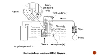
ELECTRICAL DISCHARGE MACHINING
Electric discharge machining (EDM), sometimes colloquially also
referred to as spark machining, spark eroding, burning, die
sinking or wire erosion, is a manufacturing process whereby a desired
shape is obtained using electrical discharges (sparks).
Material is removed from the workpiece by a series of rapidly recurring
current discharges between two electrodes, separated by
a dielectric liquid and subject to an electric voltage.
One of the electrodes is called the tool-electrode, or simply the ‘tool’ or
‘electrode’, while the other is called the workpiece-electrode, or
‘workpiece’.
4.
HISTORY
The beginningof EDM came during the Second World War, when two Russian
physicists B.R. and N.I. Lazarenko published their study on The Inversion of the Electric
Discharge Wear Effect. which related to the application to manufacturing technology of the
capacity of electrical discharges, under controlled distribution, to remove metal.
EDM was being used at that time to remove broken taps and drills.
The early “Tap- Busters” disintegrated taps with hand fed electrodes, burning a hole in
the center of the tap or drill, leaving the remaining fragments that could be picked
out.
This saved workpieces and very expensive parts from being scrapped and having to
be made over again.
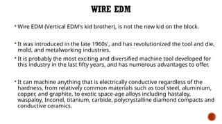
WIRE EDM
WireEDM (Vertical EDM's kid brother), is not the new kid on the block.
It was introduced in the late 1960s', and has revolutionized the tool and die,
mold, and metalworking industries.
It is probably the most exciting and diversified machine tool developed for
this industry in the last fifty years, and has numerous advantages to offer.
It can machine anything that is electrically conductive regardless of the
hardness, from relatively common materials such as tool steel, aluminium,
copper, and graphite, to exotic space-age alloys including hastaloy,
waspaloy, Inconel, titanium, carbide, polycrystalline diamond compacts and
conductive ceramics.
7.
CONT..
The wiredoes not touch the workpiece, so there is no physical
pressure imparted on the workpiece compared to grinding wheels
and milling cutters.
The amount of clamping pressure required to hold small, thin and
fragile parts is minimal, preventing damage or distortion to the
workpiece.
9.
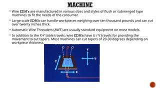
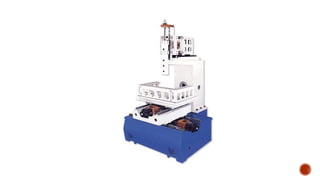
MACHINE
Wire EDM’sare manufactured in various sizes and styles of flush or submerged type
machines to fit the needs of the consumer.
Large scale EDM’s can handle workpieces weighing over ten thousand pounds and can cut
over twenty inches thick.
Automatic Wire Threaders (AWT) are usually standard equipment on most models.
In addition to the X-Y table travels, wire EDM’s have U / V travels for providing the
movement to cut tapers. Most machines can cut tapers of 20-30 degrees depending on
workpiece thickness.
10.
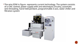
The wireEDM in figure represents current technology. The system consists
of a CNC control, power supply with anti-electrolysis circuitry, automatic
wire threading, hand held pendant, programmable Z-axis, water chiller and
filtration system.
11.
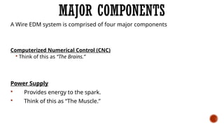
MAJOR COMPONENTS
A WireEDM system is comprised of four major components
Computerized Numerical Control (CNC)
Think of this as “The Brains.”
Power Supply
Provides energy to the spark.
Think of this as “The Muscle.”
12.
CONT..
Mechanical Section
Worktable,workstand, taper unit, and wire drive mechanism.
(This is the actual machine tool.)
Think of this as “The Body.”
Dielectric System
The water reservoir where filtration, condition of the water (resistivity/conductivity)
and temperature of the water is provided and maintained.
Think of this as “The Nourishment.”
13.
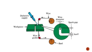
PRINCIPLE OF WIREELECTRICAL DISCHARGE MACHINING
The Spark Theory on a wire EDM is basically the same as that of the vertical EDM process.
In wire EDM, the conductive materials are machined with a series of electrical discharges
(sparks) that are produced between an accurately positioned moving wire (the electrode)
and the workpiece.
High frequency pulses of alternating or direct current is discharged from the wire to the
workpiece with a very small spark gap through an insulated dielectric fluid (water).
The heat of each electrical spark, estimated at around 15,000° to 21,000° Fahrenheit,
erodes away a tiny bit of material that is vaporized and melted from the workpiece. (Some
of the wire material is also eroded away).
These particles (chips) are flushed away from the cut with a stream of de-ionized water
through the top and bottom flushing nozzles.
14.
COMPUTER NUMERICAL CONTROL(CNC)
Today’s numerical control is produced with the needs of the operator in mind.
Programs, machine coordinates, cutting speeds, graphics and relevant information is
displayed on a color monitor, with easy to use menus.
The numerical control offers the capabilities of scaling, mirror imaging, rotation, axis
exchange and assist programs.
This enables an operator to produce an entire family of parts from a single program
without the need to edit the program.
15.
CONT..
Mirror imagingis great for left and right handed parts.
Scaling is useful when working with "shrink factors" for plastic cavities or extrusion
dies.
Assist programs find the edge of parts, vertically align the wire, and perform
centering routines that are very useful to the operator when setting up jobs.
One of the most important features that the control handles is offset. Programs are
created and written for the center of the tool (wire) to follow the outline of the part.
Lets say you are using a .010" diameter wire and it cuts a .012" slot with the power
settings provided for the particular material.
17.
POWER SUPPLY
Whenwire EDM machines were first introduced in the United States, they
were equipped with power supplies that could achieve less than one
square inch per hour.
Today, most machines are rated to cut over twenty square inches per
hour and faster.
Faster or slower speeds are obtained depending on the workpiece
material, part thickness, wire diameter, type of wire, nozzle position,
flushing condition and required part accuracy. .
18.
CONT..
Adaptive Controlis yet another improvement where high speed circuitry has
improved the spark gap sensitivity, reaction time of the servo motors, and
changes to the power.
With these improved capabilities, wire breakage is reduced to a minimum,
making today’s machines far more "forgiving" than in the past.
19.
MECHANICAL SECTION
Table movement
Machine movement is accomplished with precision lead screws with recirculating ball
bearings on all axes that are driven by AC motors.
Before shipping, the machine’s position is checked and any errors or backlash are
corrected by pitch error compensation that is permanently stored in the computers
memory.
21.
WIRE PATH
Whenwire EDM was first introduced, copper wire was used on the machines because it
conducted electricity the best.
But as speeds increased, its limitations were soon discovered.
The low tensile strength of copper wire made it subject to wire breaks when too much
tension was applied.
Poor flushability was another problem, due to coppers high thermal conductivity.
22.
CONT..
Wire diametersrange from .004" through .014" with .010" being the most
commonly used.
The wire originates from a supply spool, then passes through a tension device
(different diameter wires require different amounts of tension to keep it
straight).
The wire then passes through a set of precision, round diamond guides, and is
then transported into a waste bin.
The wire can only be used once, due to it being eroded from the EDM process.
23.
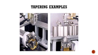
ADVANCEMENTS IN TAPERCUTTING
Most Wire EDM’s are equipped with a programmable "Z" axis giving precise control
of the upper guide assembly to ensure accurate tapers.
The rigid U and V axis is positioned away from the work area to avoid moisture,
contamination and deflection from the high pressure flush.
These axes provide movement to the top portion of the wire to produce taper
angles of up to +/- 30 degrees.
24.
CONT..
Tapering valuescan be changed within the program.
This is useful for mold applications or form tools that have different side and
frontal taper relief angles.
The machine control knows where the upper and lower guide are in relation to
the worktable.
The amount of taper angle, and direction the wire is tilted in relation to the
program path is in the program.
25.
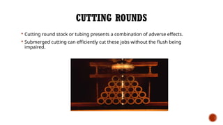
CUTTING ROUNDS
Cuttinground stock or tubing presents a combination of adverse effects.
Submerged cutting can efficiently cut these jobs without the flush being
impaired.
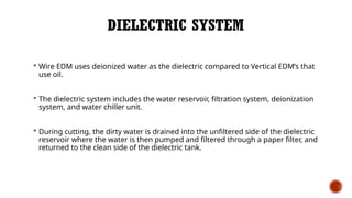
DIELECTRIC SYSTEM
WireEDM uses deionized water as the dielectric compared to Vertical EDM’s that
use oil.
The dielectric system includes the water reservoir, filtration system, deionization
system, and water chiller unit.
During cutting, the dirty water is drained into the unfiltered side of the dielectric
reservoir where the water is then pumped and filtered through a paper filter, and
returned to the clean side of the dielectric tank.
28.
SUBMERGED MACHINING
Submergedmachining is extremely useful for applications that
generally have poor flushing conditions.
Some applications and examples where submerged machining is more
practical would be
Cutting large taper angles
Tall workpieces
Laminations
Tubes
Irregular shaped parts
Workpieces with undercuts
Cutting very close to the edge of the workpiece.
29.
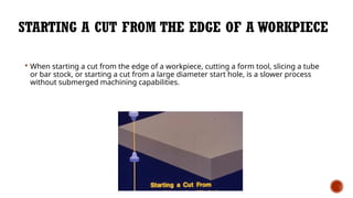
STARTING A CUTFROM THE EDGE OF A WORKPIECE
When starting a cut from the edge of a workpiece, cutting a form tool, slicing a tube
or bar stock, or starting a cut from a large diameter start hole, is a slower process
without submerged machining capabilities.
30.
PREVENTIVE MAINTENANCE
Youwouldn't drive your car five years or more without changing the oil.
You wouldn't let ten or more years pass without painting your house.
Well, EDM machines need some tender, loving care too.
But, it's not as bad as you might think! Preventive maintenance on your house (painting)
takes twenty hours or more; maintenance on your EDM usually consumes twenty to
thirty minutes a week or less.
31.
ADVANTAGE & DISADVANTAGES
Advantagesof Electro discharge machining (EDM)
Smaller holes can be easy machined.
No contact between tool and work piece then tool life is increase.
Any complex shape can be machined.
Disadvantages of Electro discharge machining (EDM)
Tool life is not longer.
Power consumption is high.
Cycle time is more.
32.
REFERENCES
Y.S. Liao,Y.Y. Chu and M.T. Yan, Study of wire breaking process and monitoring of WEDM,
International Journal of Machine Tools & Manufacture, 37 (1997) pp. 555-567.
2. R. E. Williams and K. P. Rajurkar, Study of wire electrical discharged machine surface
characteristics, Journal of Materials Processing Technology,28(1991) pp. 127-138
3. S.S Mohapatra, Amar pattnaik,Optimization of WEDM process parameters using
Taguchi method, International Journal of Advanced manufacturing Technology (2006)