Download to read offline
![50 International Journal for Modern Trends in Science and Technology
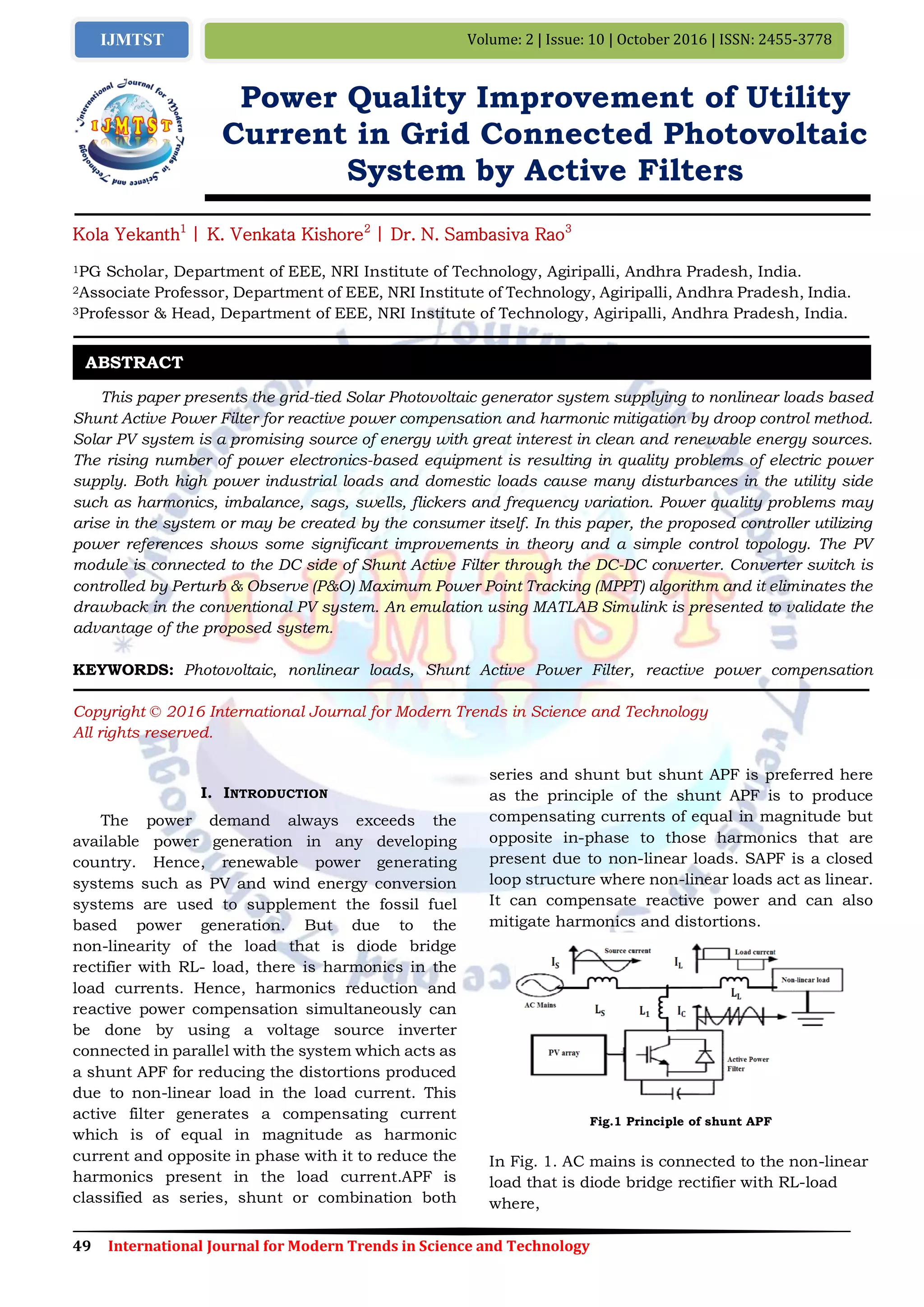
Power Quality Improvement of Utility Current in Grid Connected Photovoltaic System by Active Filters
𝐼 𝑆 - Source current
𝐼 𝐿 - Load current produced due to non-linear load
𝐼𝐶 – Compensating current produced by shunt APF
to mitigate harmonics
𝐿 𝑆 - Source inductance
𝐿 𝐿 - Load inductance
𝐿1 – Coupling inductance
Here, the shunt APF produced compensating
currents of equal in magnitude but opposite
in-phase to those harmonics that are present due
to non-linear loads which results in mitigation of
harmonics at load current. Generally, the voltage
source inverters (VSI) are used to convert the power
of the PV system to inject it to the distribution
system. But here, the VSI act as a multifunctional
device which is used for energy conversion and also
for harmonics elimination as well as reactive power
compensation simultaneously. This control
strategy incorporates P-Q solution as in shunt
active power filter technique. This control
technique is same as technique used in shunt filter
to reduce harmonics in the distribution network
due to non-linear loads in the system.
This paper is organized as follows Section II
provides overview on PV cell, its basic theory,
connections modeling and effect of temperature
and irradiation on PV panel. Section III described
MPPT P & O algorithm and its implementation for
maximum power extraction from a PV system
connected to a DC/DC Boost converter and its
need in PV power generation along with its
waveforms. Section IV presents shunt APF design
and its control algorithm with implementation of
shunt APF control technique for inverter control.
Section V describes the obtained simulation results
and its discussions Section VI presents the
conclusion along with scope for future work.
II. PHOTOVOLTAIC SYSTEMS
PV cells are made of semiconductor materials,
such as silicon. For solar cells, a thin
semiconductor wafer is specially treated to form an
electric field, positive on one side and negative on
the other. When light energy strikes the solar cell,
electrons are knocked loose from the atoms in the
semiconductor material. If electrical conductors
are attached to the positive and negative sides,
forming an electrical circuit, the electrons can be
captured in the form of an electric current - that is,
electricity. This electricity can then be used to
power a load . A PV cell can either be circular or
square in construction.
Figure 2 Basic Structure of PV Cell
A. Modeling of PV Array
Figure 3 Equivalent circuit of a PV cell
The building block of PV arrays is the solar cell,
which is basically a p-n junction that directly
converts light energy into electricity: it has a
equivalent circuit as shown below in Figure 3.
The current source Iph represents the cell
photo current; Rj is used to represent the
non-linear impedance of the p-n junction; Rsh and
Rs are used to represent the intrinsic series and
shunt resistance of the cell respectively. Usually
the value of Rsh is very large and that of Rs is very
small, hence they may be neglected to simplify the
analysis. PV cells are grouped in larger units called
PV modules which are further interconnected in
series-parallel configuration to form PV arrays or
PV generators[3].The PV mathematical model used
to simplify our PV array is represented by the
equation:
(1)
where I is the PV array output current; V is the
PV array output voltage; ns is the number of cells
in series and np is the number of cells in parallel; q
is the charge of an electron; k is the Boltzmann’s
constant; A is the p-n junction ideality factor; T is
the cell temperature (K); Irs is the cell reverse
saturation current. The factor A in equation (3.5)
determines the cell deviation from the ideal p-n
junction characteristics; it ranges between 1-5 but
for our case A=2.46 [3].](https://image.slidesharecdn.com/170ijmtst021010-161030060533/75/Power-Quality-Improvement-of-Utility-Current-in-Grid-Connected-Photovoltaic-System-by-Active-Filters-2-2048.jpg)
![51 International Journal for Modern Trends in Science and Technology
Volume: 2 | Issue: 10 | October 2016 | ISSN: 2455-3778IJMTST
The cell reverse saturation current Irs varies with
temperature according to the following equation:
(2)
Where Tr is the cell reference temperature, Irr is
the cell reverse saturation temperature at Tr and
EG is the band gap of the semiconductor used in
the cell.
The temperature dependence of the energy gap of
the semi conductor is given by [20]:
(3)
The photo current Iph depends on the solar
radiation and cell temperature as follows:
(4)
where Iscr is the cell short-circuit current at
reference temperature and radiation, Ki is the
short circuit current temperature coefficient, and S
is the solar radiation in mW/cm2. The PV power
can be calculated using equation (3.5) as follows:
(5)
Figure 4 I-V and PV curve characteristics
The current to voltage characteristic of a solar
array is non-linear, which makes it difficult to
determine the MPP. The Figure below gives the
characteristic I-V and P-V curve for fixed level of
solar irradiation and temperature.
III. MAXIMUM POWER POINT TRACKING SYSTEM
Maximum power point tracking is an essential
part of a photovoltaic system. Photovoltaic systems
have a distinct operating point that provides
maximum power. An MPPT actively seeks this
operating point. Maximum Power Point Tracking,
normally known as MPPT, is an electronic
arrangement that find the voltage (VMPP) or current
(IMPP) routinely at which a PV modules should
operate to achieve the maximum power output
(PMPP) under rapidly-changing environmental
conditions. It operates the PV modules in a way
that permits the modules to generate all the power
they are capable of.
Solar irradiation that hits the photovoltaic
modules has a variable character depending on the
latitude, orientation of the solar field, the season
and hour of the day. During the course of a day, a
shadow may be cast on the cell that may be
foreseen, as in the case of a building near the solar
field or unforeseeable as those created by clouds.
Also the energy produced by each photovoltaic cell
depends on the irradiation and temperature. From
these considerations, the necessity to identify
instant by instant that particular point on the V-I
characteristic of the PV generator in which there is
the maximum amount of power transfer to the grid
occurs. The generated energy from PV systems
must be maximize as the efficiency of solar panels
is low. For that reason to get the maximum power,
PV system is repeatedly equipped with maximum
power point (MPP) tracker. Several MPP pursuit
techniques are proposed and implemented in
recent years
Figure 5 Need of MPPT
Based on the approach used for generation of
the control signal as well as the PV system behavior
around the steady state conditions, they are
usually classified into the following groups:
1. Offline methods
Open circuit voltage (OCV) method
Short circuit current method (SCC)
Artificial intelligence
2. Online methods
Perturbation and observation method
(P&O)
Extremum seeking control method (ESC)
Incremental conductance method (Inc
Cond).
3. Hybrid methods](https://image.slidesharecdn.com/170ijmtst021010-161030060533/75/Power-Quality-Improvement-of-Utility-Current-in-Grid-Connected-Photovoltaic-System-by-Active-Filters-3-2048.jpg)
![52 International Journal for Modern Trends in Science and Technology
Power Quality Improvement of Utility Current in Grid Connected Photovoltaic System by Active Filters
A. Perturb and Observe (P&O)
The most commonly used MPPT algorithm is
P&O method. This algorithm uses simple feedback
arrangement and little measured parameters. In
this approach, the module voltage is periodically
given a perturbation and the corresponding output
power is compared with that at the previous
perturbing cycle. In this algorithm a slight
perturbation is introduce to the system. This
perturbation causes the power of the solar module
various. If the power increases due to the
perturbation then the perturbation is continued in
the same direction. After the peak power is reached
the power at the MPP is zero and next instant
decreases and hence after that the perturbation
reverses.
When the stable condition is arrived the
algorithm oscillates around the peak power point.
In order to maintain the power variation small the
perturbation size is remain very small. The
technique is advanced in such a style that it sets a
reference voltage of the module corresponding to
the peak voltage of the module. A PI controller then
acts to transfer the operating point of the module to
that particular voltage level. It is observed some
power loss due to this perturbation also the fails to
track the maximum power under fast changing
atmospheric conditions. But remain this technique
is very popular and simple.
Figure 6 The flow chart of the P&O algorithm
IV. SHUNT ACTIVE POWER FILTER WITH PV SYSTEM
A Shunt Active Filter (SAPF) is the bidirectional
current converter with six switches having
combination of both switching network and
filter-components. Structure of this power filter is
dependent on the control technique of VSI having a
capacitor for the purpose of DC energy storage and
the inverter output has been connected to
Non-linear load having diode rectifier bridge with a
RL-load. In each of the switches the diodes are
connected in anti-parallel arrangement with the
IGBTs to permit current flow in either direction.
For compensation of reactive power the PV
interconnected shunt APF injects real PV power to
a distribution line at PCC and also reduces
harmonic in load currents caused by nonlinear
loads by injecting compensating current. This filter
is connected in shunt that means in parallel with
the nonlinear load. This active filter has capability
of detecting the harmonic currents caused by the
nonlinear loads and then injects a current of equal
magnitude and opposite in phase with the
non-linear load current which is called
compensating current to reduce the harmonics
present in load currents due to Non-linear load.
Hence, the resulting current is in form of a
fundamental frequency sinusoidal current which is
drawn at PCC in distribution network.
Fig.7 Schematic diagram of a PV system connected to a
Shunt APF
A Shunt APF generally consists of the following
Blocks:
і) IGBT based voltage source inverter (VSI)
ii) DC energy storage
iii) Active control unit
1 p–q theory Based Control
Akagi et al in 1983 [3] developed P-Q theory or
“instantaneous active-reactive Power theory” for
controlling the active filters. This can be achieved
by transforming the voltage and load current into
α-β co-ordinates.](https://image.slidesharecdn.com/170ijmtst021010-161030060533/75/Power-Quality-Improvement-of-Utility-Current-in-Grid-Connected-Photovoltaic-System-by-Active-Filters-4-2048.jpg)
![53 International Journal for Modern Trends in Science and Technology
Volume: 2 | Issue: 10 | October 2016 | ISSN: 2455-3778IJMTST
Fig.8 Block diagram of p-q compensation theory
V. SIMULATION RESULTS
A. Conventional Simulation Circuit
Fig 9 Conventional Simulation Circuit
Fig 10 VSC with Filter
(i) Case Study for Balanced and unbalanced load:
To analyze the performance of the proposed
system under balanced and unbalanced load
conditions, source voltage as well as source current
is set as sinusoidal but not in phase. The SAF is
required to compensate the reactive power only. At
t=0.05 to 0.4, the inverter is switched on. At this
instant the inverter starts injecting the
compensating current so as to compensate the
phase difference between the source voltage and
current. The supply current is the sum of load
current and injected SAF output current. During
the initial period, there is no load deviation in the
load. Hence, the programmable three-phase AC
voltage source feeds the total active power to the
load. Figure 7.3 shows the waveforms of (a) Grid
Current, (b) Load Current, (c) Inverter current. The
real power generated from PV system is supply to
the load required demand.
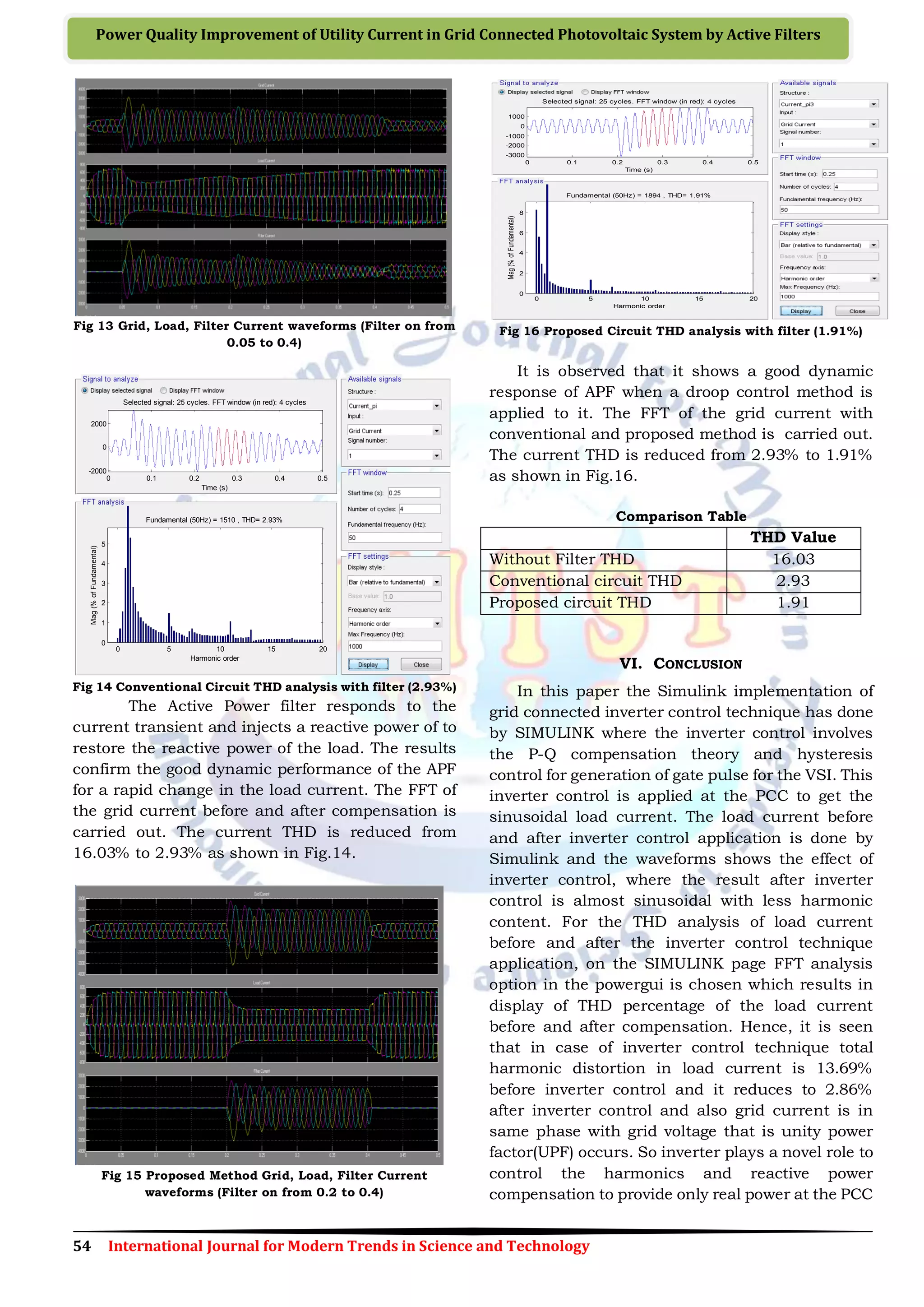
Fig 11 Grid, Load, Filter Current waveforms (Filter on from
0.05 to 0.4)
During the unbalanced load condition, the
transient load current changes occur. The Active
Power filter is switched on at time between t = 0.05
to 0.4. From figure 11 it is observed that the Grid
current is distorted from t= 0 to 0.05. At 0.05 filter
is switched on then the current oscillates at 0.05
and it stabilizes at 0.1 and again the grid current
gets distorted due to the switch off of filter at 0.4
Fig 12 Conventional Circuit THD analysis without filter
(16.03%)
GRID
5 kHz - 500V
Boost Converter
Discrete,
Ts = Ts s.
powergui
v
+
-
A
B
C
Three-Phase Source
A
B
C
A
B
CSignal 1
Signal Builder
Scope3
Scope2
Scope1
Product
Ir
m
+
-
PV Array
A
B
C
Non Linear
Load
Non Linear
Load
L1
Irradiance
(W/m^2)
g
C
E
IGBT1
Vdc
[I_PV]
Goto3
m_PV
[V_PV]
Goto1
[A]
Goto Vdc
From4
D
From3[V_PV]
[I_PV]
m_PV
From
Enable
MPPT
Display
Diode1
Deblock
Converters
I_grid
I_Load
I_AF
Data Acquistion
V_PV
I_PV
Enable
Pulses
Boost Converter
Control (MPPT)
A
B
C
a
b
c
B_Load
A
B
C
a
b
c
B
+
-
A
B
C
VSC
Grid Current
Load Current
Filter Current
<V_PV>
<I_PV>
5
-
4
+
3
C
2
B
1
A v
+
-
220
Vdc_ref
ic_pi
A
B
C
a
b
c
A
B
C
a
b
c
A
B
C
a
b
c
Out1
Subsystem1
In1
In2
Out1
Subsystem
Scope
Ic
Iabc
g
Pulse
Generator
Pulse generator
PI
Control
PI Control
g
A
B
C
+
-
Inverter3
g
A
B
C
+
-
Inverter1
g
A
B
C
+
-
Inverter
Vabc
Iabc
P
Q
V_dq
InstataneousPower
V_dc
Iabc_A
V_dc
Iabc_NL
Vabc
A
B
C
A
B
C
Coupling
Inductor1
A
B
C
A
B
C
Coupling
Inductor
Posc
Q
Vdq
I_comp
Compensating Current
butter
A
B
C
a
b
c
ACTIVE
abc
abc
abc
P_Loss
POSC
Q
V_dq
0 0.1 0.2 0.3 0.4 0.5
-2000
0
2000
Selected signal: 25 cycles. FFT window (in red): 4 cycles
Time (s)
0 5 10 15 20
0
5
10
15
20
Harmonic order
Fundamental (50Hz) = 599.6 , THD= 16.03%
Mag(%ofFundamental)](https://image.slidesharecdn.com/170ijmtst021010-161030060533/75/Power-Quality-Improvement-of-Utility-Current-in-Grid-Connected-Photovoltaic-System-by-Active-Filters-5-2048.jpg)
![55 International Journal for Modern Trends in Science and Technology
Volume: 2 | Issue: 10 | October 2016 | ISSN: 2455-3778IJMTST
of the distribution system. Hence, it can be
concluded that by use of Shunt APF the harmonics
due to a non-linearity of load is compensated to a
large value to provide sinusoidal output current of
multiple of fundamental frequency and also
reactive power is compensated to provide only real
power at the distribution system.
REFERENCES
[1] B. Subudhi, R. Pradhan, “ A Comparative Study on
Maximum Power Point Tracking Techniques for
Photovoltaic Power Systems” IEEE Transactions on
Sustainable energy, vol. 4, no. 1, January 2013.
[2] H. Akagi, “Instantaneous Power Theory and
Applications to Power Conditioning”, February 2007,
Wiley-IEEE Press.
[3] R. Panigrahi, B. Subudhi and P. C Panda, “Model
predictive-based shunt active power filter with a new
reference current estimation strategy”, IET Power
Electron., 2015, Vol. 8, Iss. 2, pp. 221–233.
[4] H. Akagi, Y. Kanmwva, K. Fujiia, A. Nabae,
“Generalized Theory of the instantaneous Reactive
Power and its Application”, Trans. IEEE Vol. 103-H,
No. 7. 1983.
[5] J. Harada and G. Zhao, “Controlled power-interface
between solar cells and ac sources,”in IEEE Conf.,
1989, pp. 22.1/1-22.1/7.
[6] Moleykutty George and Kartik Prasad Basu
“Three-Phase Shunt Active Power Filter “American
Journal of Applied Sciences 5 (8), 2008 pp.909-916.
[7] Ayman Blofan, Patrice Wira,”PV energy generation
for an autonomous shunt active power filter”, 2011.
[8] H. Akagi, “New Trends in Active Filters for Power
Conditioning,” IEEE Trans. on Industry
Applications, 1996, vol. 32, no. 6, pp. 1312-1322.
[9] Hiren Patel and Vivek Agarwal, “Maximum Power
Point Tracking Scheme for PV Systems Operating
Under Partially Shaded Conditions”, IEEE
Transactions on Industrial Electronics, Vol.55, No.4,
pp 1689-1698, 2008.
[10]T. Esram and P. L. Chapman, “Comparison of
photovoltaic array maximum power point tracking
techniques,” IEEE Trans. on Energy Conversion, vol.
22, no. 2, June 2007.
[11]M. C. Benhabib and S. Saadate, “New Control
approach for four wire active power filter based on
the use of synchronous reference frame,” Elsevier
Electric power systems Research 73, 2005, 353-362.
[12]Eswaran Chandra Sekaran , “Analysis and
simulation of a new shunt active Power filter using
cascaded multilevel inverter” Journal of electrical
engineering, vol. 58, no. 5, 2007, 241–249.
[13]B. Boukezata, A.Chaoui, J P. Gaubert and M.
Hachemi, “Active Power Filter in a transformer-less
Grid Connected Photovoltaic System” Balkan
Journal of electrical & computer engineering, 2014,
vol.2, no.3.
[14]M. Park, N.G. Seong and I.K. Yu, “A Novel
Photovoltaic Power Generation System including the
Function of Shunt Active Filter,” KIEE International
Transactions on EMECS, Vol. 3B-2, pp. 103- 110,
June, 2003.
[15]M. Elshaer, A. Mohamed, and O. Mohammed,
“Smart Optimal Control of DC-DC Boost Converter
in PV Systems” IEEE Transmission and Distribution
Conference and Exposition Latin America, 2010, pp.
978-1-4577-0487-1/10.
[16]Zulkifile Ibrahim, “Performance investigation of
photovoltaic grid connection for shunt active power
filter with different PWM generation” 20th November
2013. Vol. 57 No.2.
[17]Ahmed M. Atallah, “Implementation of perturb and
Observe MPPT of PV system with direct Control
method using buck and buck-boost Converters
Emerging Trends in Electrical”, Electronics &
Instrumentation Engineering: An International
Journal(EEIEJ), Vol. 1, No. 1, February 2014.
[18]Ayman Blorfan, Patrice Wira, “A three-phase hybrid
active power filter With photovoltaic generation and
Hysteresis current control” 2011 IEEE.
[19]Rachid Belaidi, “Shunt active power filter connected
to a photovoltaic array for compensating harmonics
and reactive power simultaneously” 4th
International Conference on Power Engineering,
Energy and Electrical Drives Istanbul, 13-17 May
2013 IEEE, Turkey.
[20]A.S. Abu Hasim, “Photovoltaic System Connected to
Three Phase Grid Connected System Incorporating
With Active Power Filter” Australian Journal of Basic
and Applied Sciences, 345-353, 2012 ISSN
1991-8178.
[21]Jeevananthan K.S, “Designing of Single Phase Shunt
Active Filter Using Instantaneous Power Theory”
International Journal of Electrical and Electronics
Research Vol. 2, Issue 2, pp: (1-10), Month: April -
June 2014.
[22]T.Chaitanya, “Modeling and Simulation of PV Array
and its Performance Enhancement Using MPPT
(P&O) Technique” International Journal of Computer
Science & Communication Networks, Vol 1(1),
September-October 2011.
[23]Thomas Geury,“Three-phase Power Controlled PV
Current Source Inverter with Incorporated Active
Power Filtering”, 2013 IEEE.
[24]Remya A.V, “Grid interconnection of PV system for 3
phase 4 wire Distribution system with power-quality
improvement” International Conf. on Electrical,
Electronics, Mechanical & Computer Engineering,
06th July-2014, Cochin, India.](https://image.slidesharecdn.com/170ijmtst021010-161030060533/75/Power-Quality-Improvement-of-Utility-Current-in-Grid-Connected-Photovoltaic-System-by-Active-Filters-7-2048.jpg)

The paper discusses improvements in power quality in grid-connected photovoltaic systems using shunt active power filters for reactive power compensation and harmonic mitigation. It highlights the issues of power quality due to nonlinear loads and presents a control strategy incorporating a Perturb & Observe (P&O) maximum power point tracking algorithm. Simulation results demonstrate significant enhancements in grid current quality, reducing total harmonic distortion from 16.03% to 2.93%.