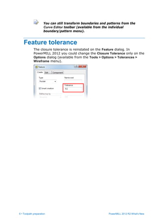
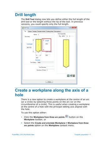
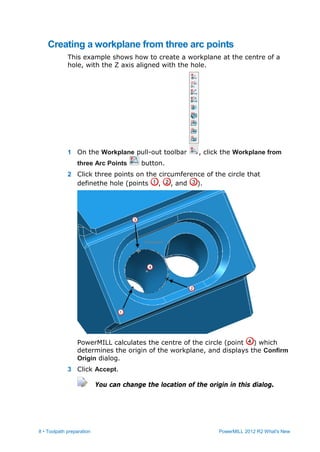
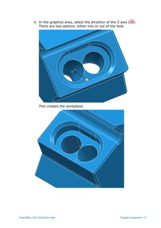
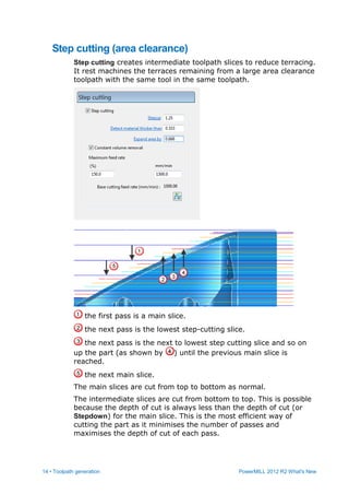
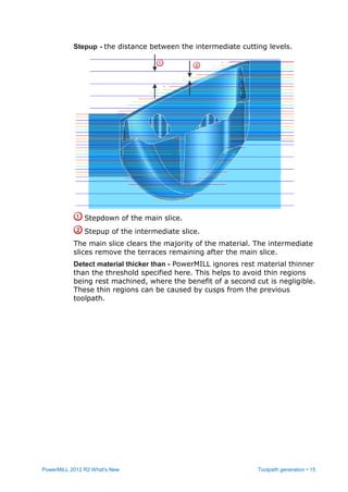
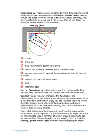
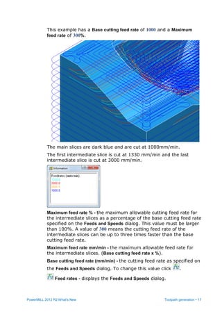
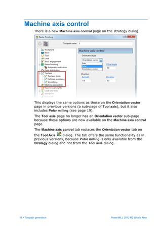
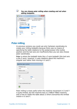
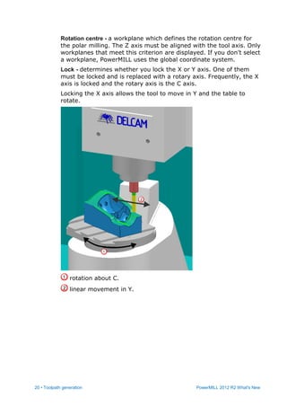
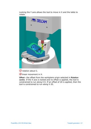
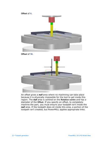
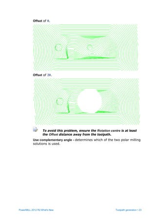
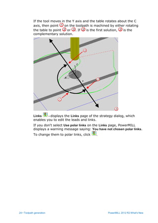
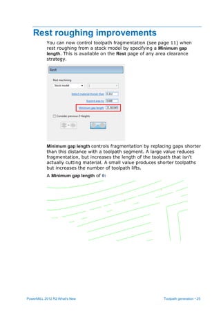
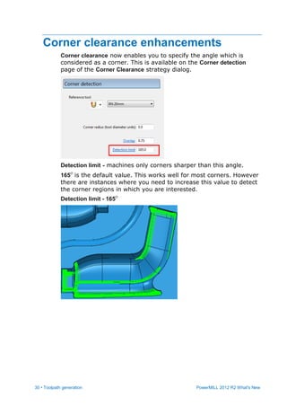
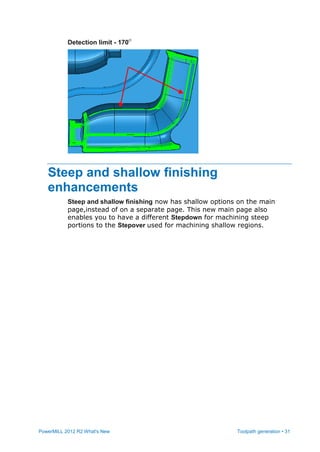
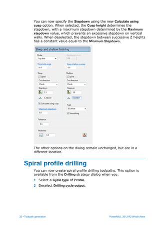
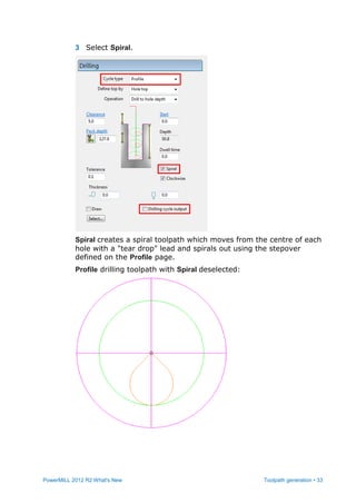
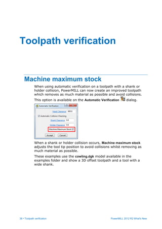
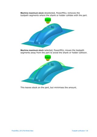
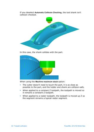
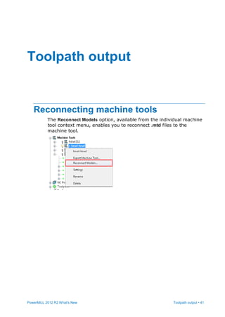
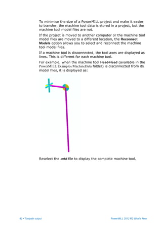
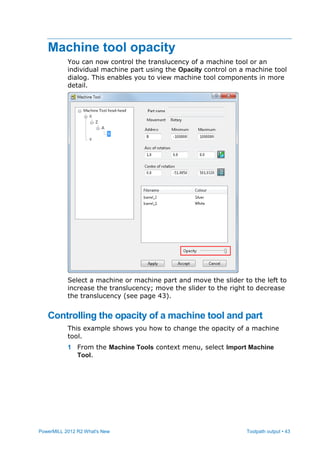
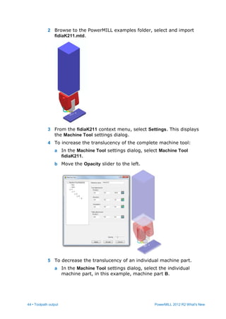
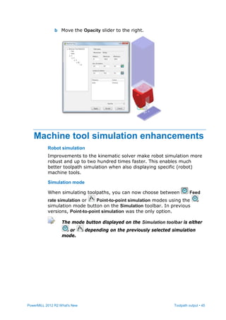
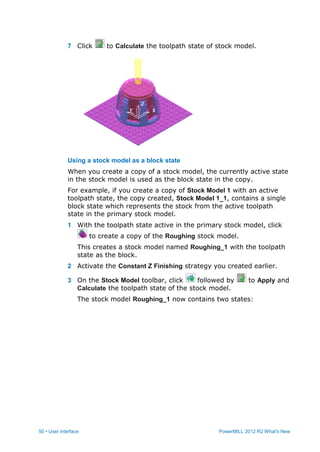
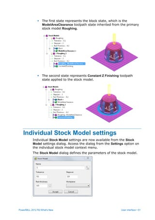
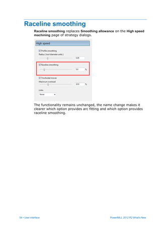
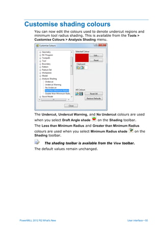
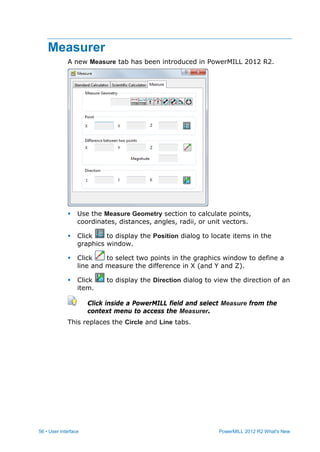
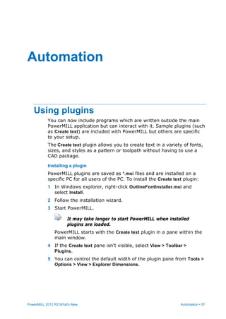
SlideShare a Scribd company logo
PowerMILL R2
What’s New
www.delcam-ams.com
Whether you are a new or long-term user of Delcam products, you
may not be aware of the complementary technologies available
from Delcam that could improve your company’s productivity.
Delcam Advanced Manufacturing Solutions offers a complete and
diverse range of CADCAM software solutions to integrate every
aspect of your production life-cycle – from designing a complex
concept, to manufacturing it and inspecting the final output –
providing you with unrivalled speed, flexibility, and ease-of-use
throughout your product development process.
Adding to your suite of Delcam solutions minimises the impact on
your daily production operations while also enabling you to enter
new markets or automate your processes with our advanced
functionality.
All products work independently or together as one complete
manufacturing solution tailored to your specific needs.
Powering your productivity
www.powershape.com
PowerSHAPE provides a complete environment to manipulate
surface form, build from wireframe, and add solid features for
prismatic parts.
 Import/export Parasolid-based systems with no translation.
 Create complex molds from solid models, complete with split
surfaces.
 Powerful surface- and face-editing tools quickly repair imported
data.
 Tools to perform non-feature-based edits quickly and efficiently.
www.powermill.com
PowerMILL is the world’s leading specialist NC CAM software for the
manufacture of complex shapes, providing advanced-machining
strategies to minimise machining time and maximise finish quality.
 World-leading high-speed machining strategies.
 Advanced 5-axis machining techniques.
 Support for 64-bit platforms and multi-threading.
 Innovative collision-avoidance methods.
 Powerful toolpath editing and tool-axis stabilisation.
www.featurecam.com
FeatureCAM is a unique CAM system that uses feature-based and
knowledge-based technologies for automated machining, minimising
programming times for mills, lathes, turn/mill, and wire machines.
 Easy to use.
 Single interface for multiple machine platforms.
 Powerful turning and milling operations from 2.5D to 5-axis.
 Multi-threading capabilities.
www.delcamforsolidworks.com
Delcam for SolidWorks is a SolidWorks Certified Gold Product that
revolutionises CAM programming inside SolidWorks.
 Integrates the feature-based technology from FeatureCAM.
 Multi-threaded toolpath algorithms from PowerMILL.
 2-axis, 3-axis, and 5-axis positional milling and drilling.
 Turning, turn/mill, and wire EDM capabilities.
 Automatic selection of cutting tools, machining strategies, and
feeds and speeds.
 Exceptional toolpath-calculation speeds.
 Set-up wizards.
 Full-machine simulation.
www.partmaker.com
PartMaker applies a patented Visual Programming approach to
automate the programming of multi-axis Swiss-type lathes and
Turn-Mill Centres.
 Easier programming of turning with live tooling via the Divide-
and-Conquer programming approach.
 Automatic process synchronisation.
 Vivid 3D simulation and crash detection.
 Wide array of proven post processors for Turn-Mill Centres and
Swiss-type lathes.
www.powerinspect.com
PowerINSPECT leads the way in today’s inspection market. It
delivers a complete CAD-based inspection solution that can accept
data from all types of hardware, including manual and CNC
coordinate measuring machines, portable arms, optical measuring
devices, and CNC machine tools.
 Part comparison against all mainstream CAD formats.
 Support for all types of measuring devices.
 Market-leading inspection reports that are quick to create and
easy to understand.
 IGES export of measured features, including digitized curves.
 Additional modules for part alignment, laser line inspection, and
tube inspection.
www.artcam.com
ArtCAM is a unique application that combines the benefits of
computerised design and CNC machining in a simple-to-use format
to create decorative products from artwork.
 Import 3D models, clipart, and other CAD system formats.
 Add geometric shapes, weaves, and textures.
 Choose from extensive visualisation and rendering materials.
 Use the comprehensive and customisable tool database for fast
toolpath-calculation.
 Powerful toolpath simulation verifies machining times and
materials.
 Design in the 3D view.
Delcam also provides a range of healthcare CADCAM solutions for
the dental, custom orthotic insoles, medical implants, and
orthopaedic footwear industries, as well as CADCAM solutions for
footwear design and manufacturing.
You can connect with Delcam in a variety of ways:
visit: www.delcam.com | watch: www.delcam.tv | learn: www.delcam.tv/lz
PowerMILL 2012 R2
What's New
Release Issue 1
PowerMILL
Copyright 1996 - 2012 Delcam plc. All rights reserved.
Delcam plc has no control over the use made of the software
described in this manual and cannot accept responsibility for any
loss or damage howsoever caused as a result of using the software.
Users are advised that all the results from the software should be
checked by a competent person, in accordance with good quality
control procedures.
The functionality and user interface in this manual is subject to
change without notice in future revisions of software.
The software described in this manual is furnished under licence
agreement and may be used or copied solely in accordance with the
terms of such licence.
Delcam plc grants permission for licensed users to print copies of
this manual or portions of this manual for personal use only.
Schools, colleges and universities that are licensed to use the
software may make copies of this manual or portions of this manual
for students currently registered for classes where the software is
used.
Acknowledgements
This documentation references a number of registered trademarks
and these are the property of their respective owners. For example,
Microsoft and Windows are either registered trademarks or
trademarks of Microsoft Corporation in the United States.
Patents
The Raceline smoothing functionality is subject to patent
applications.
Patent granted: GB 2374562 Improvements Relating to Machine
Tools
Patent granted: US 6,832,876 Machine Tools
Some of the functionality of the ViewMill and Simulation modules of
PowerMILL is subject to patent applications.
Patent granted: GB 2 423 592 Surface Finish Prediction
Licenses
Intelligent cursor licensed under U.S. patent numbers 5,123,087
and 5,371,845 (Ashlar Inc.)
PowerMILL 2012 R2. Published on 30 January 2012
PowerMILL 2012 R2 What's New Contents • i
Contents
Summary of new features 1
Toolpath preparation...........................................................................................1
Toolpath generation............................................................................................2
Toolpath verification............................................................................................2
Toolpath output...................................................................................................3
User interface .....................................................................................................3
Automation..........................................................................................................3
General enhancements.......................................................................................4
Toolpath preparation 5
Transformation enhancements ...........................................................................5
Geometry transformations ..................................................................................5
Feature tolerance................................................................................................6
Drill length...........................................................................................................7
Create a workplane along the axis of a hole.......................................................7
Creating a workplane from three arc points................................................8
Tool assembly zoom and pan controls..............................................................10
Toolpath generation 11
Area clearance step cutting ..............................................................................11
Step cutting (area clearance) ...................................................................14
Machine axis control .........................................................................................18
Polar milling..............................................................................................19
Rest roughing improvements............................................................................25
Flat machining improvements...........................................................................26
Enhancements to move toolpath start points....................................................27
Warning about plunge moves into stock ...........................................................29
Corner clearance enhancements......................................................................30
Steep and shallow finishing enhancements......................................................31
Spiral profile drilling ..........................................................................................32
Direction for Parametric spiral finishing.............................................................35
Drilling thickness...............................................................................................35
Toolpath transform enhancements ...................................................................36
Toolpath verification 38
Machine maximum stock ..................................................................................38
Toolpath output 41
ii • Contents PowerMILL 2012 R2 What's New
Reconnecting machine tools.............................................................................41
Machine tool opacity .........................................................................................43
Controlling the opacity of a machine tool and part....................................43
Machine tool simulation enhancements............................................................45
User interface 47
Stock Models toolbar ........................................................................................47
Using the Stock Model Toolbar ................................................................49
Individual Stock Model settings.........................................................................51
Individual Tool State dialog...............................................................................53
Raceline smoothing ..........................................................................................54
Customise shading colours...............................................................................55
Measurer...........................................................................................................56
Automation 57
Using plugins ....................................................................................................57
Tools > Plugins.........................................................................................59
Macro programming enhancements .................................................................61
Macro debugger .......................................................................................61
General enhancements 64
Copying toolpath and tool data to the clipboard................................................64
Adding a custom entry to an entity context menu .............................................65
Index 69
PowerMILL 2012 R2 What's New Summary of new features • 1
PowerMILL is the leading NC CAM software specialising in the
manufacture of complex shapes typically found in the toolmaking,
automotive, and aerospace industries. PowerMILL 2012 R2 offers all
of the original features of PowerMILL 2012, but with numerous
improvements. The most significant improvements are described in
this document.
Toolpath preparation
 There are three enhancements to transformations:
 PowerMILL now stores transformed entities in the same folder
as the initial entity (see page 5).
 You can choose the origin for transformations (see page 5).
 There is a new Geometry Transform toolbar for transforming
boundaries and patterns (see page 5).
 The closure tolerance is reinstated on the Feature dialog (see
page 6).
 You can define either the full length of the drill tool or the length
without the tip of the tool (see page 7).
 A new way to create a workplane along the axis of a hole using
the new Workplane from three arc points option (see page 7).
 You can zoom in the Tool Assembly view (see page 10).
Summary of new features
2 • Summary of new features PowerMILL 2012 R2 What's New
Toolpath generation
 There is a new Step cutting option which minimises terracing
when creating area clearance toolpaths with a large stepdown
(see page 11). It rest machines the terraces remaining from a
large area clearance toolpath with the same tool in the same
toolpath.
 You can now create milling toolpaths using polar rather than
Cartesian coordinates (see page 18).
 You can now control toolpath fragmentation when rest roughing
from a stock model (see page 11).
 When Flat machining, you can chose to ignore the parts of the
model containing triangles (see page 26).
 You can make multiple changes to toolpath start points at one
time (see page 27).
 If a toolpath plunges into stock material PowerMILL now displays
a warning message (see page 38).
 Corner clearance enables you to choose the angle which is
considered as a corner (see page 30).
 Steep and shallow finishing now has the shallow options on the
main page (see page 31).
 You can create spiral profile drilling toolpaths (see page 32).
 For parametric spiral toolpaths, the Cut direction options are now
Clockwise and Anticlockwise, which more accurately reflect the
machining style (see page 35).
 The thickness specified on the main Drilling strategy page is now
different to the thickness specified on the Automatic verification
page of the drilling strategy (see page 35).
 You can now choose whether to append all transformed toolpaths
into one composite toolpath or keep them as individual toolpaths
(see page 36).
Toolpath verification
When verifying a toolpath with a shank or holder collision,
PowerMILL now creates an improved toolpath which removes as
much material as possible and avoids collisions (see page 38).
PowerMILL 2012 R2 What's New Summary of new features • 3
Toolpath output
 You can reconnect the machine tool model to a project (see page
41).
 You can control the opacity of a machine tool (see page 41).
 There are some general enhancements to machine tool
simulation (see page 45):
 Robot simulation is faster and more robust.
 You can choose between toolpath point-to-point simulation
mode or a feed rate simulation mode.
 You can now move the machine tool to its home position.
User interface
 There are several changes to the Stock Model user interface:
 A new Stock Model toolbar makes it easier to work with Stock
Models (see page 49).
 Individual stock model menu options are now available in a
single Stock Model settings dialog (see page 51).
 Individual tool state menu options are now available in a
single Stock Model Tool State dialog (see page 53).
 You can now drag and drop to rearrange stock model states in
the explorer.
Rearranging stock model states invalidates stock model
calculations.
 Raceline smoothing replaces Smoothing allowance on the High
speed machining page of strategy dialogs (see page 54).
 You can now edit the colours used to denote undercut regions
and minimum tool radius shading (see page 55).
 The new Measure tab replaces the Circle and Line tabs (see page
56).
Automation
 You can now include Plugin programs to provide additional
functionality within PowerMILL. Plugins are written outside the
main PowerMILL application but can interact with it (see page
57).
4 • Summary of new features PowerMILL 2012 R2 What's New
 There are several enhancements to the Macro programming
language (see page 61).
 There is a new Macro debugger to test, debug, step-through and
track variables in your macros (see page 61).
General enhancements
 PowerMILL now makes more effective use of memory (see page
64).
 You can export models as .stl files even when no machine
operations have taken place (see page 64).
 You can copy toolpath and tool data into the Windows clipboard
(see page 64).
 You can add a custom menu option to an individual entity
context menu (see page 65).
 You can now add custom options to PowerMILL entity context
menus (see page 65).
PowerMILL 2012 R2 What's New Toolpath preparation • 5
Transformation enhancements
There are two enhancements to transformations:
 PowerMILL now stores transformed entities in the same folder as
the initial entity.
 In previous versions, the default origin for transformations was
the centre of the bounding box containing all the entities. Now,
there is a second option of the origin of the active workplane.
All the transform toolbars (Move, Rotate, Mirror, Multiple
Transform) on curve, workplane and toolpath transforms have
two additional options. For example, looking at the Move toolbar:
Workplane origin - when selected, the active workplane is the
origin. If no workplane is active then the global coordinate
system is the origin.
Bounding box origin - when selected, the origin is the centre
of the bounding box containing all the entities.
Geometry transformations
There is a new Geometry Transform toolbar (available from the
individual boundary/pattern Edit > Transform menu) for transforming
boundaries and patterns. This toolbar is similar to the Toolpath
Transform and Workplane Transform toolbars.
Toolpath preparation
6 • Toolpath preparation PowerMILL 2012 R2 What's New
You can still transform boundaries and patterns from the
Curve Editor toolbar (available from the individual
boundary/pattern menu).
Feature tolerance
The closure tolerance is reinstated on the Feature dialog. In
PowerMILL 2012 you could change the Closure Tolerance only on the
Options dialog (available from the Tools > Options > Tolerances >
Wireframe menu).
PowerMILL 2012 R2 What's New Toolpath preparation • 7
Drill length
The Drill Tool dialog now lets you define either the full length of the
drill tool or the length without the tip of the tool. In previous
versions, you could specify only the full length.
Create a workplane along the axis of a
hole
There is a new option to create a workplane at the centre of an arc
(or a circle) by selecting three points on the arc (or on the
circumference of a circle). This is useful when creating a workplane
at the centre of a hole with the principal editing axis aligned with
the hole.
To use this option either:
 Click the Workplane from three arc points button on the
Workplane toolbar; or
 Select the Create and orientate Workplane > Workplane from three
arc points option on the Workplane context menu.
8 • Toolpath preparation PowerMILL 2012 R2 What's New
Creating a workplane from three arc points
This example shows how to create a workplane at the centre of a
hole, with the Z axis aligned with the hole.
1 On the Workplane pull-out toolbar , click the Workplane from
three Arc Points button.
2 Click three points on the circumference of the circle that
definethe hole (points , , and ).
PowerMILL calculates the centre of the circle (point ) which
determines the origin of the workplane, and displays the Confirm
Origin dialog.
3 Click Accept.
You can change the location of the origin in this dialog.
PowerMILL 2012 R2 What's New Toolpath preparation • 9
4 In the graphics area, select the direction of the Z axis ( ).
There are two options, either into or out of the hole.
This creates the workplane.
10 • Toolpath preparation PowerMILL 2012 R2 What's New
Tool assembly zoom and pan controls
You can now zoom into the Tool Assembly view. The zoom control in
the Tool Assembly area of a toolpath dialog enables you to view the
tool assembly in more detail.
Select the zoom level from the list, or slide the bar to select the
zoom level you want.
When the cursor hovers over the tool assembly, it changes to .
Click and drag the view to look at sections of the tool assembly.
PowerMILL 2012 R2 What's New Toolpath generation • 11
Area clearance step cutting
There is a new Step Cutting option which minimises terracing when
creating area clearance toolpaths with a large stepdown. It rest
machines the terraces remaining from a large area clearance
toolpath with the same tool in the same toolpath.
The difference between rest machining and step cutting are:
Rest machining Step cutting
Normally uses a different
(smaller) tool to the tool
used in the area clearance
toolpath.
Uses the same tool.
Creates a separate toolpath. Creates one, combined
toolpath.
Machines the terraces down
the part.
Machines the main slices as
normal (down the part) and
machines the step cutting
rest slices upwards from the
last main slice.
Toolpath generation
12 • Toolpath generation PowerMILL 2012 R2 What's New
Step cutting is available for Model Area Clearance, Model Profile,
Model Rest Area Clearance, and Model Rest Profile strategies.
Standard area clearance toolpath without rest machining or step
cutting:
PowerMILL 2012 R2 What's New Toolpath generation • 13
The same toolpath with step cutting:
The main slices extend over the whole part, but the step-cutting
slices extend only as far as they are needed to remove the
terracing.
14 • Toolpath generation PowerMILL 2012 R2 What's New
Step cutting (area clearance)
Step cutting creates intermediate toolpath slices to reduce terracing.
It rest machines the terraces remaining from a large area clearance
toolpath with the same tool in the same toolpath.
the first pass is a main slice.
the next pass is the lowest step-cutting slice.
the next pass is the next to lowest step cutting slice and so on
up the part (as shown by ) until the previous main slice is
reached.
the next main slice.
The main slices are cut from top to bottom as normal.
The intermediate slices are cut from bottom to top. This is possible
because the depth of cut is always less than the depth of cut (or
Stepdown) for the main slice. This is the most efficient way of
cutting the part as it minimises the number of passes and
maximises the depth of cut of each pass.
PowerMILL 2012 R2 What's New Toolpath generation • 15
Stepup - the distance between the intermediate cutting levels.
Stepdown of the main slice.
Stepup of the intermediate slice.
The main slice clears the majority of the material. The intermediate
slices remove the terraces remaining after the main slice.
Detect material thicker than - PowerMILL ignores rest material thinner
than the threshold specified here. This helps to avoid thin regions
being rest machined, where the benefit of a second cut is negligible.
These thin regions can be caused by cusps from the previous
toolpath.
16 • Toolpath generation PowerMILL 2012 R2 What's New
Expand area by - rest areas are expanded by this distance, measured
along the surface. You can use it with Detect material thicker than to
reduce the areas to be machined to the details (say, corners), and
then to offset these areas slightly to ensure that all the detail (for
example, on the corners) is machined.
- model
- thickness
- true rest material (outlined in pink)
- actual rest material detected (blue hatched area)
- amount you need to expand the area by to include all the rest
material
- undetected material (black area)
- tool
- reference tool
Use the Expand area by option to increase the rest area (the blue
hatched area) and eliminate the undetected area (the black area).
Constant volume removal - increases the Feed rate of the
intermediate slices. Because the stepdown of the intermediate slices
is less than that of the main slice, you can increase the feed rate of
the intermediate slices while maintaining the tool load. Each
intermediate slice can have an increasing feed rate as the depth of
cut gets progressively smaller.
PowerMILL determines the increase in feed rate for intermediate
slices based on the depth of cut. So if the maximum depth of cut for
an intermediate slice is half that of a main slice, the feed rate can
be twice as fast. To see the effect of the varying feed rate, select
Drawing Options > Draw Feeds from the individual toolpath menu.
PowerMILL 2012 R2 What's New Toolpath generation • 17
This example has a Base cutting feed rate of 1000 and a Maximum
feed rate of 300%.
The main slices are dark blue and are cut at 1000mm/min.
The first intermediate slice is cut at 1330 mm/min and the last
intermediate slice is cut at 3000 mm/min.
Maximum feed rate % - the maximum allowable cutting feed rate for
the intermediate slices as a percentage of the base cutting feed rate
specified on the Feeds and Speeds dialog. This value must be larger
than 100%. A value of 300 means the cutting feed rate of the
intermediate slices can be up to three times faster than the base
cutting feed rate.
Maximum feed rate mm/min - the maximum allowable feed rate for
the intermediate slices. (Base cutting feed rate x %).
Base cutting feed rate (mm/min) - the cutting feed rate as specified on
the Feeds and Speeds dialog. To change this value click .
Feed rates - displays the Feeds and Speeds dialog.
18 • Toolpath generation PowerMILL 2012 R2 What's New
Machine axis control
There is a new Machine axis control page on the strategy dialog.
This displays the same options as those on the Orientation vector
page in previous versions (a sub-page of Tool axis), but it also
includes Polar milling (see page 19).
The Tool axis page no longer has an Orientation vector sub-page
because these options are now available on the Machine axis control
page.
The Machine axis control tab replaces the Orientation vector tab on
the Tool Axis dialog. The tab offers the same functionality as in
previous versions, because Polar milling is only available from the
Strategy dialog and not from the Tool axis dialog.
PowerMILL 2012 R2 What's New Toolpath generation • 19
You can choose polar milling when creating and not when
editing toolpaths.
Polar milling
In previous versions you could use only Cartesian coordinates to
create your milling toolpaths because there was no means of
specifying the table rotations to the postprocessor (the tooltip
position and the tool axis are insufficient).Now you can also choose
polar coordinates.
Polar is where the toolpath looks like a 3-axis toolpath (the tool axis
is the Z axis), however, it uses rotations about the machine's
singular axis rather than moving in X and Y.
Polar milling is most useful when the machine movement in X and Y
is quite limited, but the machine tool is a TABLE-TABLE machine,
and is free to rotate the table about Z which overcomes the limited
motion in X and Y.
20 • Toolpath generation PowerMILL 2012 R2 What's New
Rotation centre - a workplane which defines the rotation centre for
the polar milling. The Z axis must be aligned with the tool axis. Only
workplanes that meet this criterion are displayed. If you don't select
a workplane, PowerMILL uses the global coordinate system.
Lock - determines whether you lock the X or Y axis. One of them
must be locked and is replaced with a rotary axis. Frequently, the X
axis is locked and the rotary axis is the C axis.
Locking the X axis allows the tool to move in Y and the table to
rotate.
rotation about C.
linear movement in Y.
PowerMILL 2012 R2 What's New Toolpath generation • 21
Locking the Y axis allows the tool to move in X and the table to
rotate.
rotation about C.
linear movement in X.
Offset - the offset from the workplane origin selected in Rotation
centre. If the X axis is locked and no offset is applied, the tool is
constrained to run along X 0. If an offset of 20 is applied, then the
tool is constrained to run along X 20.
22 • Toolpath generation PowerMILL 2012 R2 What's New
Offset of 0.
Offset of 50.
An offset gives a null area where no machining can take place
because it is physically impossible for the tool to get inside this
region. The null area is centred on the Rotation centre and has a
diameter of the Offset. If you specify an offset, to completely
machine the part, you must ensure your toolpath isn't inside the
null area. If the toolpath does sit inside this area, a portion of the
toolpath isn't created, but PowerMILL applies appropriate links.
PowerMILL 2012 R2 What's New Toolpath generation • 23
Offset of 0.
Offset of 20.
To avoid this problem, ensure the Rotation centre is at least
the Offset distance away from the toolpath.
Use complementary angle - determines which of the two polar milling
solutions is used.
24 • Toolpath generation PowerMILL 2012 R2 What's New
If the tool moves in the Y axis and the table rotates about the C
axis, then point on the toolpath is machined by either rotating
the table to point or . If is the first solution, is the
complementary solution.
Links - displays the Links page of the strategy dialog, which
enables you to edit the leads and links.
If you don't select Use polar links on the Links page, PowerMILL
displays a warning message saying: You have not chosen polar links.
To change them to polar links, click .
PowerMILL 2012 R2 What's New Toolpath generation • 25
Rest roughing improvements
You can now control toolpath fragmentation (see page 11) when
rest roughing from a stock model by specifying a Minimum gap
length. This is available on the Rest page of any area clearance
strategy.
Minimum gap length controls fragmentation by replacing gaps shorter
than this distance with a toolpath segment. A large value reduces
fragmentation, but increases the length of the toolpath that isn't
actually cutting material. A small value produces shorter toolpaths
but increases the number of toolpath lifts.
A Minimum gap length of 0:
26 • Toolpath generation PowerMILL 2012 R2 What's New
A Minimum gap length of the default value:
You must have a Rest machining reference type of Stock model
to enable this option.
In previous versions, you had no control over this value:
 In PowerMILL 2012, the gap length was the current default
value.
 In PowerMILL 2011, the gap length was zero.
Flat machining improvements
There is an additional option of Find flats on triangles on the Flat
machining page of 3D Model area clearance strategies and on the
Offset flat and Raster flat finishing strategies to specify whether to
consider parts of the model containing triangles. In PowerMILL
2012, flat machining considered areas of the model which contained
triangles. Now, you can choose to ignore them.
PowerMILL 2012 R2 What's New Toolpath generation • 27
Find flats on triangles, when selected, finds flat areas on models
containing triangles and surfaces. When deselected, PowerMILL
doesn't consider parts of the model containing triangles.
Enhancements to move toolpath start
points
You can now make multiple changes to toolpath start points
simultaneously using the Batch option on the Move Start Points
toolbar.
This toolbar is available from the Move Start Points button on the
Toolpath toolbar.
Batch - batches toolpath start points edits and applies them
when you reselect this button. You can batch edits in either or
mode, but not in a mixture of both.
For example:
28 • Toolpath generation PowerMILL 2012 R2 What's New
1 Click the Batch button.
2 Click the Move toolpath start points by Line button.
3 Sketch a line .
4 Sketch another line .
5 Click the Batch button.
This moves the edited toolpath start points.
The Undo button undoes one operation at a time. So
you must click twice to revert to the original.
Clicking , discards all the batched edits.
PowerMILL 2012 R2 What's New Toolpath generation • 29
Warning about plunge moves into
stock
If you calculate a toolpath with a plunge move into stock material,
PowerMILL displays a warning message. This reminds you to add
appropriate lead in moves. In previous versions, this warning was
displayed when editing a toolpath, but not on initial creation.
The individual toolpath Edit menu now enables you to check
whether a toolpath has:
 any plunge moves into stock
 missing lead ins on any connection moves
30 • Toolpath generation PowerMILL 2012 R2 What's New
Corner clearance enhancements
Corner clearance now enables you to specify the angle which is
considered as a corner. This is available on the Corner detection
page of the Corner Clearance strategy dialog.
Detection limit - machines only corners sharper than this angle.
165 is the default value. This works well for most corners. However
there are instances where you need to increase this value to detect
the corner regions in which you are interested.
Detection limit - 165
PowerMILL 2012 R2 What's New Toolpath generation • 31
Detection limit - 170
Steep and shallow finishing
enhancements
Steep and shallow finishing now has shallow options on the main
page,instead of on a separate page. This new main page also
enables you to have a different Stepdown for machining steep
portions to the Stepover used for machining shallow regions.
32 • Toolpath generation PowerMILL 2012 R2 What's New
You can now specify the Stepdown using the new Calculate using
cusp option. When selected, the Cusp height determines the
stepdown, with a maximum stepdown determined by the Maximum
stepdown value, which prevents an excessive stepdown on vertical
walls. When deselected, the stepdown between successive Z heights
has a constant value equal to the Minimum Stepdown.
The other options on the dialog remain unchanged, but are in a
different location.
Spiral profile drilling
You can now create spiral profile drilling toolpaths. This option is
available from the Drilling strategy dialog when you:
1 Select a Cycle type of Profile.
2 Deselect Drilling cycle output.
PowerMILL 2012 R2 What's New Toolpath generation • 33
3 Select Spiral.
Spiral creates a spiral toolpath which moves from the centre of each
hole with a "tear drop" lead and spirals out using the stepover
defined on the Profile page.
Profile drilling toolpath with Spiral deselected:
34 • Toolpath generation PowerMILL 2012 R2 What's New
Profile drilling toolpath with Spiral selected:
If you select Spiral on the main page, then the Profile page displays
the spiral Stepover rather than the Final profile pass options.
PowerMILL 2012 R2 What's New Toolpath generation • 35
Spiral stepover is the distance between adjacent passes:
Direction for Parametric spiral finishing
The milling strategy used for parametric spiral toolpaths more
accurately reflects the machining style. In PowerMILL 2012 R2 the
Direction field has two options:
Clockwise - produces a conventional milling toolpath when
machining a pocket and a climb milling toolpath when machining
a boss.
Anticlockwise - produces a climb milling toolpath when machining
a pocket and a conventional milling toolpath when machining a
boss.
In PowerMILL 2012, the Cut direction field had the two options,
Climb and Conventional. These options produced the expected
results when machining a pocket, but not when machining a boss.
Drilling thickness
The thickness specified on the main Drilling strategy page is now
different to the thickness specified on the Automatic verification page
of the drilling strategy.
36 • Toolpath generation PowerMILL 2012 R2 What's New
 The thickness specified on the main Drilling page is used for
toolpath generation. This is the thickness used for toolpath
generation and enables you to drill a hole deeper than the hole
feature by creating a drilling toolpath with a negative axial
thickness. This is useful for through holes.
 The thickness specified on the Automatic verification page is used
for collision checking. This ensures there is no shank or holder
collisions at the top of the hole by collision checking the toolpath
to a positive thicknesses, specified on the Automatic Verification
page.
If you enter a different toolpath thickness to verification thickness
PowerMILL displays a warning message:
The verification thickness is different from the drilling thickness.
Toolpath transform enhancements
You can now choose whether to append all transformed toolpaths
into one composite toolpath or keep them as individual toolpaths. In
previous versions they were created as individual toolpaths. This
new Toolpath append option is available on the Toolpath Transform
toolbar.
For example, creating a multiple transform on a constant Z
toolpath called CZ.
PowerMILL 2012 R2 What's New Toolpath generation • 37
Selecting creates one new toolpath:
Deselecting creates eight new toolpaths:
38 • Toolpath verification PowerMILL 2012 R2 What's New
Machine maximum stock
When using automatic verification on a toolpath with a shank or
holder collision, PowerMILL can now create an improved toolpath
which removes as much material as possible and avoid collisions.
This option is available on the Automatic Verification dialog.
When a shank or holder collision occurs, Machine maximum stock
adjusts the tool tip position to avoid collisions whilst removing as
much material as possible.
These examples use the cowling.dgk model available in the
examples folder and show a 3D offset toolpath and a tool with a
wide shank.
Toolpath verification
PowerMILL 2012 R2 What's New Toolpath verification • 39
Machine maximum stock deselected, PowerMILL removes the
toolpath segments where the shank or holder collides with the part.
Machine maximum stock selected, PowerMILL moves the toolpath
segments away from the part to avoid the shank or holder collision.
This leaves stock on the part, but minimises the amount.
40 • Toolpath verification PowerMILL 2012 R2 What's New
If you deselect Automatic Collision Checking, the tool shank isn't
collision checked.
In this case, the shank collides with the part.
When using the Machine maximum stock option:
 The cutter doesn't need to touch the part, it is as close as
possible to the part, and the holder and shank are collision-safe.
 When applied to a constant Z toolpath, the toolpath is moved so
it remains a constant Z toolpath.
 When applied to a raster toolpath, the toolpath is moved up Z so
the segment remains a typical raster segment.
PowerMILL 2012 R2 What's New Toolpath output • 41
Reconnecting machine tools
The Reconnect Models option, available from the individual machine
tool context menu, enables you to reconnect .mtd files to the
machine tool.
Toolpath output
42 • Toolpath output PowerMILL 2012 R2 What's New
To minimise the size of a PowerMILL project and make it easier
to transfer, the machine tool data is stored in a project, but the
machine tool model files are not.
If the project is moved to another computer or the machine tool
model files are moved to a different location, the Reconnect
Models option allows you to select and reconnect the machine
tool model files.
If a machine tool is disconnected, the tool axes are displayed as
lines. This is different for each machine tool.
For example, when the machine tool Head-Head (available in the
PowerMILL Examples/MachineData folder) is disconnected from its
model files, it is displayed as:
Reselect the .mtd file to display the complete machine tool.
PowerMILL 2012 R2 What's New Toolpath output • 43
Machine tool opacity
You can now control the translucency of a machine tool or an
individual machine part using the Opacity control on a machine tool
dialog. This enables you to view machine tool components in more
detail.
Select a machine or machine part and move the slider to the left to
increase the translucency; move the slider to the right to decrease
the translucency (see page 43).
Controlling the opacity of a machine tool and part
This example shows you how to change the opacity of a machine
tool.
1 From the Machine Tools context menu, select Import Machine
Tool.
44 • Toolpath output PowerMILL 2012 R2 What's New
2 Browse to the PowerMILL examples folder, select and import
fidiaK211.mtd.
3 From the fidiaK211 context menu, select Settings. This displays
the Machine Tool settings dialog.
4 To increase the translucency of the complete machine tool:
a In the Machine Tool settings dialog, select Machine Tool
fidiaK211.
b Move the Opacity slider to the left.
5 To decrease the translucency of an individual machine part.
a In the Machine Tool settings dialog, select the individual
machine part, in this example, machine part B.
PowerMILL 2012 R2 What's New Toolpath output • 45
b Move the Opacity slider to the right.
Machine tool simulation enhancements
Robot simulation
Improvements to the kinematic solver make robot simulation more
robust and up to two hundred times faster. This enables much
better toolpath simulation when also displaying specific (robot)
machine tools.
Simulation mode
When simulating toolpaths, you can now choose between Feed
rate simulation or Point-to-point simulation modes using the
simulation mode button on the Simulation toolbar. In previous
versions, Point-to-point simulation was the only option.
The mode button displayed on the Simulation toolbar is either
or depending on the previously selected simulation
mode.
46 • Toolpath output PowerMILL 2012 R2 What's New
Feed rate simulation - toolpath is simulated based on feed
rates. The simulation speed, managed using the speed control, is
a multiple of the feed rate.
Point-to-point simulation - toolpath is simulated from point-to-
point. The simulation speed, managed using the speed control,
controls the number of toolpath points covered in a second.
Home position
There is an additional button of Home on the Position tab of the
Machine Information dialog (available from on the Machine Tool
toolbar). This moves the machine tool to its home position.
PowerMILL 2012 R2 What's New User interface • 47
Stock Models toolbar
The Stock Models toolbar enables you to create and edit Stock
Models. Stock Models are an alternative method to using reference
toolpaths when rest machining.
To display the Stock Models toolbar, either:
 From the Stock Models context menu, select Toolbar; or
 Select View > Toolbar > Stock Models from the menu.
Create a Stock Model - creates a new empty stock model and
displays the Stock Model settings dialog where you can set up
parameters for the stock model.
- selects a stock model and activates it. This list
displays the available Stock Models in a project.
- selects a stock model state in the active stock
model and activates it. This list displays the available stock model
states in the selected stock model.
Stock Model Settings - displays the Stock Model settings dialog
where you can edit the currently active stock model parameters.
Queue Stock Model - adds the selected Stock Model to the
calculation queue.
Calculate Stock Model - calculates the selected Stock Model.
Copy Stock Model - creates a copy of the Stock Model. This
creates a new stock model with a single block state.
User interface
48 • User interface PowerMILL 2012 R2 What's New
Import - displays the Import Stock Model dialog which allows you
to import Stock Models.
Use the dialog to browse and select *.stkmd files (Stock Model
files). This loads a new Stock Model entity with a single block
state.
Export - exports the stock model. Select this option to display
the Save Stock Model dialog. Enter a Stock Model name, browse to
the save directory and click Save.
This saves the current active state of a stock model into a new
stock model as a single state.
Apply Block - creates a stock model of the block. All block types
are supported (arbitrary, boundary, or rectangular).
Apply Active Toolpath - applies the active toolpath after the active
stock model state. If no state is active, the toolpath is added after
the last stock model state and is made the active state.
Apply Active Tool - applies the active tool after the active stock
model state. If no state is active, the tool is added after the last
stock model state and is made the active state.
Remove Active Stock Model State - removes the active stock
model state from the stock model. This invalidates all subsequent
stock model states.
Draw Stock Model - draws the stock model as a wireframe or
shaded stock model.
Draw Wireframe - draws the stock model as a wireframe.
Draw Shaded - draws a shaded stock model.
Show Material - displays the rest, removed, and all stock
material.
Show All Material - displays all stock material.
Show Rest Material - displays material left over after the stock
model state operation.
Show Removed Material - displays material removed after the
stock model state operation.
Delete Stock Model - deletes the active stock model.
PowerMILL 2012 R2 What's New User interface • 49
Using the Stock Model Toolbar
This example shows how to create and manipulate stock models
using the Stock Model toolbar. This uses the radknob.dmt model
available in the PowerMILL examples folder.
Creating a basic stock model
1 Calculate a Block and using a 15 mm End Mill tool:
a Create a Model Area Clearance toolpath with default values.
b Create a Constant Z Finishing toolpath with default values.
2 From the Stock Models context menu, select Toolbar to display
the Stock Model toolbar.
3 Click to create a new stock model. This displays the Stock
Model dialog.
a Change the name to Roughing.
b Click Accept.
4 Click to apply the block to the stock model.
5 Click to calculate the block state of stock model.
6 With the Model Area Clearance strategy activated, click to
Apply the active toolpath to the stock model.
50 • User interface PowerMILL 2012 R2 What's New
7 Click to Calculate the toolpath state of stock model.
Using a stock model as a block state
When you create a copy of a stock model, the currently active state
in the stock model is used as the block state in the copy.
For example, if you create a copy of Stock Model 1 with an active
toolpath state, the copy created, Stock Model 1_1, contains a single
block state which represents the stock from the active toolpath
state in the primary stock model.
1 With the toolpath state active in the primary stock model, click
to create a copy of the Roughing stock model.
This creates a stock model named Roughing_1 with the toolpath
state as the block.
2 Activate the Constant Z Finishing strategy you created earlier.
3 On the Stock Model toolbar, click followed by to Apply and
Calculate the toolpath state of the stock model.
The stock model Roughing_1 now contains two states:
PowerMILL 2012 R2 What's New User interface • 51
 The first state represents the block state, which is the
ModelAreaClearance toolpath state inherited from the primary
stock model Roughing.
 The second state represents Constant Z Finishing toolpath
state applied to the stock model.
Individual Stock Model settings
Individual Stock Model settings are now available from the Stock
Model settings dialog. Access the dialog from the Settings option on
the individual stock model context menu.
The Stock Model dialog defines the parameters of the stock model.
52 • User interface PowerMILL 2012 R2 What's New
To display the Stock Model dialog:
 From the Stock Models context menu, select Create Stock Model;
or
 From the individual stock models context menu, select Settings;
or
 From the Stock Models toolbar, select .
Name - the name of the stock model.
- click to unlock the stock model and enable editing.
A Stock Model is automatically locked when it is used by
another entity.
Tolerance - determines the tolerance of a slice when a new stock
model is created. The stock model is stored as a set of closed slices
of the solid stock in X and Y. You cannot change this value after the
stock model state has been calculated.
Stepover - the step between slices. You cannot change this value
after the stock model state has been calculated.
Rest thickness - determines the minimum thickness displayed when
using the Drawing Options > Show Rest Material option. The stock
model ignores rest material thinner than this threshold. It is similar
to the Detect material thicker than option on the Boundary dialog.
Refresh - click to refresh rest material. You can refresh rest
material only if the Drawing Options > Show Rest Material option is
enabled and you have modified the Rest thickness.
Workplane - select a workplane from the list to define the stock
model. You cannot set or change the workplane after the stock
model has been calculated.
Accept - accepts the values in the dialog.
Cancel - cancels the dialog without making any changes.
PowerMILL 2012 R2 What's New User interface • 53
Individual Tool State dialog
Individual stock model tool state settings are now available from the
Stock Model Tool State settings dialog. Access the dialog from the
Settings option on the individual stock model tool state context
menu.
ConstantZ - the name of the stock model.
2 - the name of the tool used to create the stock model tool state.
Radial thickness - the radial thickness used to define the
stock model tool state.
Axial thickness - the axial thickness used to define the
stock model tool state.
Corner radius - the corner radius used to define the stock model tool
state.
Workplane - lists available workplanes in the project. Select a
workplane to use it to define the stock model tool state. You cannot
set or change the workplane after the stock model state has been
calculated.
Boundary - lists available boundaries in the project. Select a
boundary to use it to define the stock model tool state. You cannot
set or change the boundary after the stock model state has been
calculated.
You cannot change or modify the Radial thickness, Axial
thickness, Corner radius, Workplane, and Boundary values for a
calculated stock model state.
54 • User interface PowerMILL 2012 R2 What's New
Raceline smoothing
Raceline smoothing replaces Smoothing allowance on the High speed
machining page of strategy dialogs.
The functionality remains unchanged, the name change makes it
clearer which option provides arc fitting and which option provides
raceline smoothing.
PowerMILL 2012 R2 What's New User interface • 55
Customise shading colours
You can now edit the colours used to denote undercut regions and
minimum tool radius shading. This is available from the Tools >
Customise Colours > Analysis Shading menu.
The Undercut, Undercut Warning, and No Undercut colours are used
when you select Draft Angle shade on the Shading toolbar.
The Less than Minimum Radius and Greater than Minimum Radius
colours are used when you select Minimum Radius shade on the
Shading toolbar.
The shading toolbar is available from the View toolbar.
The default values remain unchanged.
56 • User interface PowerMILL 2012 R2 What's New
Measurer
A new Measure tab has been introduced in PowerMILL 2012 R2.
 Use the Measure Geometry section to calculate points,
coordinates, distances, angles, radii, or unit vectors.
 Click to display the Position dialog to locate items in the
graphics window.
 Click to select two points in the graphics window to define a
line and measure the difference in X (and Y and Z).
 Click to display the Direction dialog to view the direction of an
item.
Click inside a PowerMILL field and select Measure from the
context menu to access the Measurer.
This replaces the Circle and Line tabs.
PowerMILL 2012 R2 What's New Automation • 57
Using plugins
You can now include programs which are written outside the main
PowerMILL application but can interact with it. Sample plugins (such
as Create text) are included with PowerMILL but others are specific
to your setup.
The Create text plugin allows you to create text in a variety of fonts,
sizes, and styles as a pattern or toolpath without having to use a
CAD package.
Installing a plugin
PowerMILL plugins are saved as *.msi files and are installed on a
specific PC for all users of the PC. To install the Create text plugin:
1 In Windows explorer, right-click OutlineFontInstaller.msi and
select Install.
2 Follow the installation wizard.
3 Start PowerMILL.
It may take longer to start PowerMILL when installed
plugins are loaded.
PowerMILL starts with the Create text plugin in a pane within the
main window.
4 If the Create text pane isn't visible, select View > Toolbar >
Plugins.
5 You can control the default width of the plugin pane from Tools >
Options > View > Explorer Dimensions.
Automation
58 • Automation PowerMILL 2012 R2 What's New
6 Control which plugins are enabled (and so available) from the
Plugin Manager dialog available from the Tools > Plugins menu
(see page 59).
You must have administrator rights to install a plugin.
PowerMILL 2012 R2 What's New Automation • 59
Tools > Plugins
The Plugin Manager shows which plugins are installed on your PC
and which are enabled.
The right side of the dialog displays all the available plugins. The
left side displays information on the selected plugin.
Status - shows which plugins are available.
- available and enabled.
- available but disabled.
- requires a newer version of PowerMILL to run. PowerMILL can
load the plugin and display its details.
- not available. PowerMILL can't load the plugin, so it can't
display any details about it. This happens if the plugin is corrupt, or
hasn't been registered correctly.
Plugin name - shows a list of all the plugins installed on this PC.
60 • Automation PowerMILL 2012 R2 What's New
Plugin summary - the right-hand pane shows a summary of the
selected plugin.
Enable all - enables all the plugins installed on this PC.
Disable all - disables all the plugins installed on this PC.
Enable/Disable - either enables the disabled plugin, or disables the
enabled plugin.
This button refers to the plugin selected in the left-hand pane.
Options - displays the Options dialog of the plugin. If the plugin
doesn't have an Options dialog this button is unavailable.
Information - displays the plugin log.
Clean up log - removes all items in the plugin log.
For more information, see Using Plugins (see page 57).
PowerMILL 2012 R2 What's New Automation • 61
Macro programming enhancements
There is a new Debug option on the Macros menu which opens the
Macro Debugger (see page 61). This replaces the Step Through Macro
option available in previous versions.
The macro programming language now includes:
 Lists (as well as arrays).
 Vector and point variables.
 An option to terminate the current macro.
 Some constants.
 Entity-based functions.
 A built-in evaluation function.
 The ability to return the pathname of the current project.
For more information, see the Macro Programming Guide.
Macro debugger
The Macro Debugger enables you to test, debug, step-through, and
track variable values in your macro.
When debugging a macro you tend to have a portion of code that
you are interested in (either to understand how it works, or why it
isn't working). To look at this portion of code you:
 Insert breakpoints at points of interest.
62 • Automation PowerMILL 2012 R2 What's New
 Run the macro using Execute. This allows you to execute your
macro up to the point of interest to ensure everything is in the
correct state.
 Use the various Step functions to understand what is going on in
your macro line by line.
 Run the macro using Execute to the next point of interest, or
to the end of the macro.
Execute - runs the macro from the current position until it
reaches either a breakpoint or the end of the macro.
shows the current position.
If you pause a macro, then Execute resumes the macro
execution.
Pause - inserts a temporary breakpoint after executing the
current line.
Stop - stops the macro from executing and returns to the start of
the macro.
The step commands execute the current line and then wait for
further debugger interaction. This enables you to see the effect of a
macro statement or command and so helps your understanding of
the macro. The variable values assigned at this point of the macro
are displayed in the right-hand pane.
Step into - executes the current line only and then waits for
further debugger interaction. If the current line is a macro function
call, then the debugger pauses before executing the first line of the
function. This allows you to check a function.
Step over - executes the current line only and then waits for
further debugger interaction. If the current line is a macro function
call, then the debugger pauses after the entire function has
executed. This is useful when you know the function works, so you
don't need to look at it in detail, but want the results from it.
Step out - executes the current line and all subsequent lines
within the block. When the block of commands ends, PowerMILL
waits for further debugger interaction.
PowerMILL 2012 R2 What's New Automation • 63
Skip next line - skips the next line without executing the
command. This is useful when you know a command will execute
successfully but takes a long time to calculate, say calculating a
toolpath. However, it can be dangerous to Skip next line because
future commands may require the output from this command.
Add breakpoint - places a breakpoint at the start of the selected
line. A breakpoint forces the macro to stop at this point. The
variable values assigned at this point of the macro are displayed in
the right-hand pane. You can insert multiple breakpoints in your
macro.
For example, if you put a breakpoint at the end of a loop you can
examine the variable values and see how they change with each
iteration. This enables you to find out if the macro is behaving as
you'd expect.
Another example is: if you put a breakpoint at the beginning of a
function you can see which variables and parameters are passed to
the function.
Delete breakpoint - removes a breakpoint from the selected line.
Delete all breakpoints - removes all breakpoints from the macro.
Reload macro - stops the current execution of the macro and
reloads the macro file. This is useful when you have fixed a problem
with your macro and want to run it again to check it.
The left pane shows the macro you are debugging.
The right pane shows the variable assignment at that point in the
macro.
If you want to run the debugger on a macro that takes an
argument in Main() you must use the command MACRO DEBUG
mymacro.mac arguments where mymacro is the name of the
macro and arguments is the list of arguments you want to
pass to the macro you are about to debug.
64 • General enhancements PowerMILL 2012 R2 What's New
There are a few general enhancements:
 PowerMILL now makes more effective use of memory. This is
particularly noticeable on large parts which now machine more
quickly.
 Arc fitting is much improved and more reliable. Arc fitting is
available from the high speed pages of area clearance, constant
Z and raster strategies.
 You can now export models as .stl files even when no machine
operations have taken place. You can determine the Triangle
export tolerance on the Options dialog (available from Tools >
Options > Export > Model menu).
Triangle export tolerance determines the accuracy used to
translate from the dgk format to an stl format.
Copying toolpath and tool data to the
clipboard
You can copy toolpath and tool data from the NC Program and Tool
Database dialog to the Windows clipboard. This is useful if you want
to create reports using other applications.
General enhancements
PowerMILL 2012 R2 What's New General enhancements • 65
To copy data in the NC Program or Tool Database dialogs, right-click
the column heading and select Copy.
This copies all data from the dialog to the Windows clipboard.
To copy specific rows, select individual rows, right-click the
column heading and select Copy.
For example, data copied from the tool database to a spreadsheet
looks similar to:
You can also copy data from the Toolpath List and Tool List
dialogs.
Adding a custom entry to an entity
context menu
You can now add custom options to PowerMILL entity context
menus.
To add a menu option to an entity context menu
1 Create an XML file and name it as the entity type it represents.
66 • General enhancements PowerMILL 2012 R2 What's New
The names allowed are: Boundary, Featureset, Group, Level,
MachineTool, Macro, Model, NCProgram, Pattern, StockModel,
Tool, Toolpath, and Workplane.
The name is not case sensitive.
2 Place the <entity_type>.xml file in the PowerMILL Homepmill
folder.
Format of the custom entity menu option
The format of the custom addition to the PowerMILL entity menu is:
<?xml version="1.0" ?>
<menupage>
<button label= "The name of the menu option"
command= 'SOME POWERMILL COMMAND/>'
</menupage>
For example, to create this sample submenu for an individual stock
model entity:
The code in the stockmodel.xml file is:
<?xml version="1.0" ?>
<menupage>
<button label= "Transform" command= 'FORM MODELTRANS
EDIT MODEL "%s" INTERACTIVE'/>
<button label="Block" command='FORM BLOCK'/>
</menupage>
Where:
PowerMILL 2012 R2 What's New General enhancements • 67
label - is the name of the menu item.
command - is the PowerMILL command.
%s - is the wildcard character which represents the individual
entity name.
Adding spaces and submenus to the menu option
To add spaces to the menu, add the <spacer/> tag to the XML
code. To add submenus, include the submenu name in a
<menupage> tag.
For example, to create this User menu and submenu called "Hello
World!" with relevant spaces:
The code in the stockmodel.xml file is:
<?xml version="1.0" ?>
<menupage>
<button label="Replace Tool"
command='EDIT TOOLPATH "%s" REPLACE_TOOL ;'
multiple_selection="allowed"/>
<button label="Undraw selected toolpaths"
command='MACRO d:/temp/test.mac "%s"'
multiple_selection="allowed"/>
<spacer/>
68 • General enhancements PowerMILL 2012 R2 What's New
<menupage label="Hello World!">
<button command='PRINT "HELLO"' label="Hello"/>
<button command='PRINT "WORLD"' label="World"/>
</menupage>
</menupage>
Enabling multiple selections for a menu option
To enable the menu option over multiple selections, add the
keywords multiple_selection="allowed" for each <button /> tag.
For example:
<button label= "Transform"
command= 'FORM MODELTRANS EDIT MODEL "%s"
INTERACTIVE'
multiple_selection="allowed"/>
PowerMILL 2012 R2 What's New Index • 69
A
Appending transformed toolpaths • 36
Arc fitting • 64
Area clearance toolpaths
Area clearance step cutting • 11
Detection limit • 30
Flat machining • 26
Flats on triangles • 26
Minimum gap length • 25
Plunge move warning • 29
Rest roughing fragmentation • 25
Automatic collision checking
Machine maximum stock • 38
Automatic verification
Machine maximum stock • 38
Thickness - drilling • 35
B
Base cutting feed rate - step cutting • 14
Batch move toolpath start points • 27
Boundary transformations • 5
Bounding box origin • 5
Breakpoints • 61
C
Colours • 55
Draft angle shading • 55
Minimum radius shading • 55
Undercut shading • 55
Complementary angle - polar milling • 19
Constant volume removal - step cutting •
14
Copying data • 64
Corner clearance
Detection limit • 30
Custom entity menu options • 65
Customise colours • 55
D
Detect area thicker than - step cutting •
14
Detection limit • 30
Draft angle shading • 55
Drill length • 7
Drilling
Drill length • 7
Spiral profile drilling • 32
Thickness - drilling • 35
E
Expand area by - step cutting • 14
F
Feature tolerance • 6
Feed rate - step cutting • 14
Finishing toolpaths
Flat machining • 26
Parametric spiral finishing • 35
Steep and shallow finishing • 31
Flat machining • 26
Flats on triangles • 26
Index
70 • Index PowerMILL 2012 R2 What's New
Fragmentation reduction • 25
G
Geometry Transform toolbar • 5
Geometry transformations • 5
M
Machine axis control • 18
Polar milling • 18, 19
Machine maximum stock • 38
Machine tools • 41
Machine tool opacity • 43
Macro debugger • 61
Breakpoints • 61
Macro programming guide • 61
Maximum feed rate - step cutting • 14
Minimum gap length • 25
Minimum radius shading • 55
Move toolpath start points • 27
P
Parametric spiral finishing • 35
Pattern transformations • 5
Plugins • 57
Plunge move warning • 29
Polar milling • 18, 19
Complementary angle - polar milling •
19
Rotation centre - polar milling • 19
Profile drilling • 32
Programs
Plugins • 57
R
Raceline smoothing • 54
Reconnecting machine tools • 41
Rest roughing fragmentation • 25
Fragmentation reduction • 25
Minimum gap length • 25
Rotation centre - polar milling • 19
S
Shading • 55
Draft angle shading • 55
Minimum radius shading • 55
Undercut shading • 55
Simulation modes
Feed rate simulation • 45
Point-to-point simulation • 45
Smoothing
Arc fitting • 64
Raceline smoothing • 54
Spiral profile drilling • 32
Steep and shallow finishing • 31
Step cutting • 14
Base cutting feed rate - step cutting •
14
Constant volume removal - step
cutting • 14
Detect area thicker than - step cutting
• 14
Expand area by - step cutting • 14
Feed rate - step cutting • 14
Maximum feed rate - step cutting • 14
Stepup - step cutting • 14
STL files • 64
Stock models • 47
Stock model settings • 51, 53
Stock model toolbar • 47, 49
T
Thickness - drilling • 35
Tolerance
Feature tolerance • 6
Tool
Drill length • 7
Tool assembly pan and zoom • 10
Tool axis
Machine axis control • 18
Polar milling • 18, 19
Toolbars
Geometry Transform toolbar • 5
Transform toolbar • 5
Toolpath start points • 27
Toolpath transformatios • 36
Toolpaths
Appending transformed toolpaths • 36
Area clearance step cutting • 11
Detection limit • 30
Flat machining • 26
PowerMILL 2012 R2 What's New Index • 71
Flats on triangles • 26
Minimum gap length • 25
Parametric spiral finishing • 35
Plunge move warning • 29
Rest roughing fragmentation • 25
Steep and shallow finishing • 31
Step cutting • 14
Toolpath transformatios • 36
Transform toolbar • 5
Transformations • 5
Appending transformed toolpaths • 36
Boundary transformations • 5
Bounding box origin • 5
Geometry transformations • 5
Pattern transformations • 5
Toolpath transformatios • 36
Workplane origin • 5
U
Undercut shading • 55
V
Verification
Machine maximum stock • 38
W
WN2012R2
Measurer • 56
Workplane from three arc points • 7, 8
Workplane origin • 5
PowerMILL R2
Powering your productivity
Delcam Headquarters | Small Heath Business Park | Birmingham | B10 0HJ | UK
+44 (0)121 766 5544 | marketing@delcam.com | www.delcam.com
To contact your local reseller, visit www.delcam.com/resellers
© Copyright Delcam plc 2012. All other trademarks are the property of their respective owners.
PowerMILL 2012
new features
www.delcam.tv/lz
www.delcam.tv
www.powermill.com
PowerMILL Learning Zone
Delcam TV
PowerMILL Website

More Related Content

What's hot

The Scrum Model
The Scrum ModelThe Scrum Model
The Scrum Model
Damian T. Gordon
 
Introduction to scaled agile framework
Introduction to scaled agile frameworkIntroduction to scaled agile framework
Introduction to scaled agile framework
Srinath Ramakrishnan
 
Google classroom ppt for teachers
Google classroom ppt for teachersGoogle classroom ppt for teachers
Google classroom ppt for teachers
DesireMaharjan
 
Fusion 360 training course
Fusion 360 training courseFusion 360 training course
Fusion 360 training course
Autodesk Fusion 360
 
Foundations of the Scaled Agile Framework 3.0
Foundations of the Scaled Agile Framework 3.0Foundations of the Scaled Agile Framework 3.0
Foundations of the Scaled Agile Framework 3.0
Willy Marroquin (WillyDevNET)
 
Agile-overview: Agile Manifesto, Agile principles and Agile Methodologies
Agile-overview: Agile Manifesto, Agile principles and Agile MethodologiesAgile-overview: Agile Manifesto, Agile principles and Agile Methodologies
Agile-overview: Agile Manifesto, Agile principles and Agile Methodologies
Balaji Sathram
 
Training games
Training gamesTraining games
Training games
HRHARIRAM
 
APPLYING LEAN SIX SIGMA FOR WASTE REDUCTION IN A MANUFACTURING ENVIRONMENT
APPLYING LEAN SIX SIGMA FOR WASTE REDUCTION IN A MANUFACTURING ENVIRONMENT APPLYING LEAN SIX SIGMA FOR WASTE REDUCTION IN A MANUFACTURING ENVIRONMENT
APPLYING LEAN SIX SIGMA FOR WASTE REDUCTION IN A MANUFACTURING ENVIRONMENT
Firdaus Albarqoni
 
Project Prioritization Process List Ranked Ppt Powerpoint Presentation Outlin...
Project Prioritization Process List Ranked Ppt Powerpoint Presentation Outlin...Project Prioritization Process List Ranked Ppt Powerpoint Presentation Outlin...
Project Prioritization Process List Ranked Ppt Powerpoint Presentation Outlin...
SlideTeam
 
Lean Six Sigma Implementation
Lean Six Sigma ImplementationLean Six Sigma Implementation
Lean Six Sigma Implementation
Darren Dolcemascolo
 
Process Improvement in Software Engineering SE25
Process Improvement in Software Engineering SE25Process Improvement in Software Engineering SE25
Process Improvement in Software Engineering SE25koolkampus
 
Scrum Events and Artifacts in Action
Scrum Events and Artifacts in ActionScrum Events and Artifacts in Action
Scrum Events and Artifacts in Action
Lemi Orhan Ergin
 
ADAPTing to Agile Development
ADAPTing to Agile DevelopmentADAPTing to Agile Development
ADAPTing to Agile Development
Mike Cohn
 
Waterfall vs agile approach scrum framework and best practices in software d...
Waterfall vs agile approach  scrum framework and best practices in software d...Waterfall vs agile approach  scrum framework and best practices in software d...
Waterfall vs agile approach scrum framework and best practices in software d...
Tayfun Bilsel
 
آشنایی با چابکی و اسکرام (Agile & scrum)
آشنایی با چابکی و اسکرام (Agile & scrum)آشنایی با چابکی و اسکرام (Agile & scrum)
آشنایی با چابکی و اسکرام (Agile & scrum)
Neda Ansari
 
Introduction to Google Classroom
Introduction to Google ClassroomIntroduction to Google Classroom
Introduction to Google Classroom
Jennifer L. Scheffer
 
3 D printing new 2015
3 D printing new 20153 D printing new 2015
3 D printing new 2015
Akhil Jose
 
Why Agile Works?
Why Agile Works?Why Agile Works?
Why Agile Works?
Aaron Medina
 
Keeping Retrospectives Fresh
Keeping Retrospectives FreshKeeping Retrospectives Fresh
Keeping Retrospectives FreshAlida Cheung
 
3D printing
3D printing3D printing
3D printing
Ansari Danish
 

What's hot (20)

The Scrum Model
The Scrum ModelThe Scrum Model
The Scrum Model
 
Introduction to scaled agile framework
Introduction to scaled agile frameworkIntroduction to scaled agile framework
Introduction to scaled agile framework
 
Google classroom ppt for teachers
Google classroom ppt for teachersGoogle classroom ppt for teachers
Google classroom ppt for teachers
 
Fusion 360 training course
Fusion 360 training courseFusion 360 training course
Fusion 360 training course
 
Foundations of the Scaled Agile Framework 3.0
Foundations of the Scaled Agile Framework 3.0Foundations of the Scaled Agile Framework 3.0
Foundations of the Scaled Agile Framework 3.0
 
Agile-overview: Agile Manifesto, Agile principles and Agile Methodologies
Agile-overview: Agile Manifesto, Agile principles and Agile MethodologiesAgile-overview: Agile Manifesto, Agile principles and Agile Methodologies
Agile-overview: Agile Manifesto, Agile principles and Agile Methodologies
 
Training games
Training gamesTraining games
Training games
 
APPLYING LEAN SIX SIGMA FOR WASTE REDUCTION IN A MANUFACTURING ENVIRONMENT
APPLYING LEAN SIX SIGMA FOR WASTE REDUCTION IN A MANUFACTURING ENVIRONMENT APPLYING LEAN SIX SIGMA FOR WASTE REDUCTION IN A MANUFACTURING ENVIRONMENT
APPLYING LEAN SIX SIGMA FOR WASTE REDUCTION IN A MANUFACTURING ENVIRONMENT
 
Project Prioritization Process List Ranked Ppt Powerpoint Presentation Outlin...
Project Prioritization Process List Ranked Ppt Powerpoint Presentation Outlin...Project Prioritization Process List Ranked Ppt Powerpoint Presentation Outlin...
Project Prioritization Process List Ranked Ppt Powerpoint Presentation Outlin...
 
Lean Six Sigma Implementation
Lean Six Sigma ImplementationLean Six Sigma Implementation
Lean Six Sigma Implementation
 
Process Improvement in Software Engineering SE25
Process Improvement in Software Engineering SE25Process Improvement in Software Engineering SE25
Process Improvement in Software Engineering SE25
 
Scrum Events and Artifacts in Action
Scrum Events and Artifacts in ActionScrum Events and Artifacts in Action
Scrum Events and Artifacts in Action
 
ADAPTing to Agile Development
ADAPTing to Agile DevelopmentADAPTing to Agile Development
ADAPTing to Agile Development
 
Waterfall vs agile approach scrum framework and best practices in software d...
Waterfall vs agile approach  scrum framework and best practices in software d...Waterfall vs agile approach  scrum framework and best practices in software d...
Waterfall vs agile approach scrum framework and best practices in software d...
 
آشنایی با چابکی و اسکرام (Agile & scrum)
آشنایی با چابکی و اسکرام (Agile & scrum)آشنایی با چابکی و اسکرام (Agile & scrum)
آشنایی با چابکی و اسکرام (Agile & scrum)
 
Introduction to Google Classroom
Introduction to Google ClassroomIntroduction to Google Classroom
Introduction to Google Classroom
 
3 D printing new 2015
3 D printing new 20153 D printing new 2015
3 D printing new 2015
 
Why Agile Works?
Why Agile Works?Why Agile Works?
Why Agile Works?
 
Keeping Retrospectives Fresh
Keeping Retrospectives FreshKeeping Retrospectives Fresh
Keeping Retrospectives Fresh
 
3D printing
3D printing3D printing
3D printing
 

Viewers also liked

Gia công nhiều trục Delcam Powermill
Gia công nhiều trục Delcam PowermillGia công nhiều trục Delcam Powermill
Gia công nhiều trục Delcam Powermill
Trung tâm Advance Cad
 
Autodesk CAM Portfolio – Russ Adams PartMaker
Autodesk CAM Portfolio – Russ Adams PartMakerAutodesk CAM Portfolio – Russ Adams PartMaker
Autodesk CAM Portfolio – Russ Adams PartMaker
Synergis Engineering Design Solutions
 
Lập trình gia công khuôn Delcam Powermill (Demo)
Lập trình gia công khuôn Delcam Powermill (Demo)Lập trình gia công khuôn Delcam Powermill (Demo)
Lập trình gia công khuôn Delcam Powermill (Demo)
Trung tâm Advance Cad
 
Thiết kế sản phẩm Delcam Powershape
Thiết kế sản phẩm Delcam PowershapeThiết kế sản phẩm Delcam Powershape
Thiết kế sản phẩm Delcam Powershape
Trung tâm Advance Cad
 
Hướng dẫn thiết kế 3D với Delcam Powershape (Demo)
Hướng dẫn thiết kế 3D với Delcam Powershape (Demo)Hướng dẫn thiết kế 3D với Delcam Powershape (Demo)
Hướng dẫn thiết kế 3D với Delcam Powershape (Demo)
Trung tâm Advance Cad
 
Autocad 3D Object
Autocad 3D ObjectAutocad 3D Object
Autocad 3D Object
nethisip13
 
Maintenance performance analysis_en_v1
Maintenance performance analysis_en_v1Maintenance performance analysis_en_v1
Maintenance performance analysis_en_v1
Alexander Stuber
 
Manual+básico+autocad+2010
Manual+básico+autocad+2010Manual+básico+autocad+2010
Manual+básico+autocad+2010
Franccesca granado
 
Plastic Mould manufacturers
Plastic Mould manufacturersPlastic Mould manufacturers
Plastic Mould manufacturers
Hongyi JIG Rapid Technologies
 
Tài liệu mastercam X7 cho người mới học (Demo)
Tài liệu mastercam X7 cho người mới học (Demo)Tài liệu mastercam X7 cho người mới học (Demo)
Tài liệu mastercam X7 cho người mới học (Demo)
Trung tâm Advance Cad
 
Curso vip de auto cad 2016
Curso vip de auto cad 2016Curso vip de auto cad 2016
Curso vip de auto cad 2016
Eduardo Kulik
 
Quality control of mould making at bluestar mould group
Quality control of mould making at bluestar mould group Quality control of mould making at bluestar mould group
Quality control of mould making at bluestar mould group
Huy Bui Van
 
Gia công 2d nâng cao mastercam X7 ( demo)
Gia công 2d nâng cao mastercam X7 ( demo)Gia công 2d nâng cao mastercam X7 ( demo)
Gia công 2d nâng cao mastercam X7 ( demo)
Trung tâm Advance Cad
 
Autocad 2015 (best presentation)
Autocad 2015 (best presentation)Autocad 2015 (best presentation)
Autocad 2015 (best presentation)
ikramuls
 
Khóa học lập trình vận hành Phay CNC
Khóa học lập trình vận hành Phay CNCKhóa học lập trình vận hành Phay CNC
Khóa học lập trình vận hành Phay CNC
Trung tâm Advance Cad
 
Lập trình gia công cơ bản Powermill (demo)
Lập trình gia công cơ bản Powermill (demo)Lập trình gia công cơ bản Powermill (demo)
Lập trình gia công cơ bản Powermill (demo)
Trung tâm Advance Cad
 
Khóa học phay 2D Mastercam
Khóa học phay 2D MastercamKhóa học phay 2D Mastercam
Khóa học phay 2D Mastercam
Trung tâm Advance Cad
 
Gia công phay 3D mastercam x7
Gia công phay 3D mastercam x7Gia công phay 3D mastercam x7
Gia công phay 3D mastercam x7
Trung tâm Advance Cad
 
Understanding lead and lag indicators
Understanding lead and lag indicatorsUnderstanding lead and lag indicators
Understanding lead and lag indicators
Improvement Skills Consulting Ltd.
 
Đào tạo gia công khuôn, phay 3D Mastercam)
Đào tạo gia công khuôn, phay 3D Mastercam)Đào tạo gia công khuôn, phay 3D Mastercam)
Đào tạo gia công khuôn, phay 3D Mastercam)
Trung tâm Advance Cad
 

Viewers also liked (20)

Gia công nhiều trục Delcam Powermill
Gia công nhiều trục Delcam PowermillGia công nhiều trục Delcam Powermill
Gia công nhiều trục Delcam Powermill
 
Autodesk CAM Portfolio – Russ Adams PartMaker
Autodesk CAM Portfolio – Russ Adams PartMakerAutodesk CAM Portfolio – Russ Adams PartMaker
Autodesk CAM Portfolio – Russ Adams PartMaker
 
Lập trình gia công khuôn Delcam Powermill (Demo)
Lập trình gia công khuôn Delcam Powermill (Demo)Lập trình gia công khuôn Delcam Powermill (Demo)
Lập trình gia công khuôn Delcam Powermill (Demo)
 
Thiết kế sản phẩm Delcam Powershape
Thiết kế sản phẩm Delcam PowershapeThiết kế sản phẩm Delcam Powershape
Thiết kế sản phẩm Delcam Powershape
 
Hướng dẫn thiết kế 3D với Delcam Powershape (Demo)
Hướng dẫn thiết kế 3D với Delcam Powershape (Demo)Hướng dẫn thiết kế 3D với Delcam Powershape (Demo)
Hướng dẫn thiết kế 3D với Delcam Powershape (Demo)
 
Autocad 3D Object
Autocad 3D ObjectAutocad 3D Object
Autocad 3D Object
 
Maintenance performance analysis_en_v1
Maintenance performance analysis_en_v1Maintenance performance analysis_en_v1
Maintenance performance analysis_en_v1
 
Manual+básico+autocad+2010
Manual+básico+autocad+2010Manual+básico+autocad+2010
Manual+básico+autocad+2010
 
Plastic Mould manufacturers
Plastic Mould manufacturersPlastic Mould manufacturers
Plastic Mould manufacturers
 
Tài liệu mastercam X7 cho người mới học (Demo)
Tài liệu mastercam X7 cho người mới học (Demo)Tài liệu mastercam X7 cho người mới học (Demo)
Tài liệu mastercam X7 cho người mới học (Demo)
 
Curso vip de auto cad 2016
Curso vip de auto cad 2016Curso vip de auto cad 2016
Curso vip de auto cad 2016
 
Quality control of mould making at bluestar mould group
Quality control of mould making at bluestar mould group Quality control of mould making at bluestar mould group
Quality control of mould making at bluestar mould group
 
Gia công 2d nâng cao mastercam X7 ( demo)
Gia công 2d nâng cao mastercam X7 ( demo)Gia công 2d nâng cao mastercam X7 ( demo)
Gia công 2d nâng cao mastercam X7 ( demo)
 
Autocad 2015 (best presentation)
Autocad 2015 (best presentation)Autocad 2015 (best presentation)
Autocad 2015 (best presentation)
 
Khóa học lập trình vận hành Phay CNC
Khóa học lập trình vận hành Phay CNCKhóa học lập trình vận hành Phay CNC
Khóa học lập trình vận hành Phay CNC
 
Lập trình gia công cơ bản Powermill (demo)
Lập trình gia công cơ bản Powermill (demo)Lập trình gia công cơ bản Powermill (demo)
Lập trình gia công cơ bản Powermill (demo)
 
Khóa học phay 2D Mastercam
Khóa học phay 2D MastercamKhóa học phay 2D Mastercam
Khóa học phay 2D Mastercam
 
Gia công phay 3D mastercam x7
Gia công phay 3D mastercam x7Gia công phay 3D mastercam x7
Gia công phay 3D mastercam x7
 
Understanding lead and lag indicators
Understanding lead and lag indicatorsUnderstanding lead and lag indicators
Understanding lead and lag indicators
 
Đào tạo gia công khuôn, phay 3D Mastercam)
Đào tạo gia công khuôn, phay 3D Mastercam)Đào tạo gia công khuôn, phay 3D Mastercam)
Đào tạo gia công khuôn, phay 3D Mastercam)
 

Similar to Power mill 2012_r2 - whats new

Cad cam cnc training center nagpur
Cad cam cnc training center nagpurCad cam cnc training center nagpur
Cad cam cnc training center nagpur
CADD MASTRE
 
BEG 2104 CAD-CAM Lec 5.doc
BEG 2104 CAD-CAM Lec 5.docBEG 2104 CAD-CAM Lec 5.doc
BEG 2104 CAD-CAM Lec 5.doc
FreddyMutua
 
Streamlining the Design of Industrial Machinery and Heavy Equipment
Streamlining the Design of Industrial Machinery and Heavy EquipmentStreamlining the Design of Industrial Machinery and Heavy Equipment
Streamlining the Design of Industrial Machinery and Heavy Equipment
Engineering Technique
 
Difference between cad &amp;cam
Difference between cad &amp;camDifference between cad &amp;cam
Difference between cad &amp;cam
Sandya Devarajan
 
Cad cam for dental sistem
Cad cam for dental sistemCad cam for dental sistem
Cad cam for dental sistem
Alfredo Nevárez
 
Introduction-to-CAD-and-CAM-Software.pptx
Introduction-to-CAD-and-CAM-Software.pptxIntroduction-to-CAD-and-CAM-Software.pptx
Introduction-to-CAD-and-CAM-Software.pptx
RaturiMohit
 
Introduction-to-CAD-and-CAM-Software.pptx
Introduction-to-CAD-and-CAM-Software.pptxIntroduction-to-CAD-and-CAM-Software.pptx
Introduction-to-CAD-and-CAM-Software.pptx
RaturiMohit
 
CNC: 2.5D AXIS vs. VIRTUAL CNC
CNC: 2.5D AXIS vs. VIRTUAL CNC CNC: 2.5D AXIS vs. VIRTUAL CNC
CNC: 2.5D AXIS vs. VIRTUAL CNC
Sisubalan Selvan
 
Specialized Industry Solutions - Presentation
Specialized Industry Solutions - PresentationSpecialized Industry Solutions - Presentation
Specialized Industry Solutions - Presentation
David Bohannon
 
Camtools presentation 14 15
Camtools presentation 14 15Camtools presentation 14 15
Camtools presentation 14 15
CAM TOOLS
 
Advanced motion controls servo drive catalog
Advanced motion controls servo drive catalogAdvanced motion controls servo drive catalog
Advanced motion controls servo drive catalog
Electromate
 
CAD CAM CAE and PLM Study
CAD CAM CAE and PLM StudyCAD CAM CAE and PLM Study
CAD CAM CAE and PLM Study
HarshadaPawar26
 
Zw3 d all-in-one
Zw3 d all-in-oneZw3 d all-in-one
Zw3 d all-in-one
Hari Mulyanto
 
Design To Manufacturing - Solidworks
Design To Manufacturing - SolidworksDesign To Manufacturing - Solidworks
Design To Manufacturing - Solidworks
Burak Kuralkan
 
Introductiontoadaptiveand3dexperience 180807145140
Introductiontoadaptiveand3dexperience 180807145140Introductiontoadaptiveand3dexperience 180807145140
Introductiontoadaptiveand3dexperience 180807145140
kailashgavare
 
Introduction to Adaptive and 3DEXPERIENCE
Introduction to Adaptive and 3DEXPERIENCE Introduction to Adaptive and 3DEXPERIENCE
Introduction to Adaptive and 3DEXPERIENCE
Adaptive Corporation
 

Similar to Power mill 2012_r2 - whats new (20)

Cam works productdemo
Cam works productdemoCam works productdemo
Cam works productdemo
 
Cad cam cnc training center nagpur
Cad cam cnc training center nagpurCad cam cnc training center nagpur
Cad cam cnc training center nagpur
 
BEG 2104 CAD-CAM Lec 5.doc
BEG 2104 CAD-CAM Lec 5.docBEG 2104 CAD-CAM Lec 5.doc
BEG 2104 CAD-CAM Lec 5.doc
 
Streamlining the Design of Industrial Machinery and Heavy Equipment
Streamlining the Design of Industrial Machinery and Heavy EquipmentStreamlining the Design of Industrial Machinery and Heavy Equipment
Streamlining the Design of Industrial Machinery and Heavy Equipment
 
Cam works
Cam worksCam works
Cam works
 
Difference between cad &amp;cam
Difference between cad &amp;camDifference between cad &amp;cam
Difference between cad &amp;cam
 
Cad cam for dental sistem
Cad cam for dental sistemCad cam for dental sistem
Cad cam for dental sistem
 
Introduction-to-CAD-and-CAM-Software.pptx
Introduction-to-CAD-and-CAM-Software.pptxIntroduction-to-CAD-and-CAM-Software.pptx
Introduction-to-CAD-and-CAM-Software.pptx
 
Introduction-to-CAD-and-CAM-Software.pptx
Introduction-to-CAD-and-CAM-Software.pptxIntroduction-to-CAD-and-CAM-Software.pptx
Introduction-to-CAD-and-CAM-Software.pptx
 
CNC: 2.5D AXIS vs. VIRTUAL CNC
CNC: 2.5D AXIS vs. VIRTUAL CNC CNC: 2.5D AXIS vs. VIRTUAL CNC
CNC: 2.5D AXIS vs. VIRTUAL CNC
 
Specialized Industry Solutions - Presentation
Specialized Industry Solutions - PresentationSpecialized Industry Solutions - Presentation
Specialized Industry Solutions - Presentation
 
Camtools presentation 14 15
Camtools presentation 14 15Camtools presentation 14 15
Camtools presentation 14 15
 
Advanced motion controls servo drive catalog
Advanced motion controls servo drive catalogAdvanced motion controls servo drive catalog
Advanced motion controls servo drive catalog
 
Rich Belfiore 2015
Rich Belfiore 2015Rich Belfiore 2015
Rich Belfiore 2015
 
CAD CAM CAE and PLM Study
CAD CAM CAE and PLM StudyCAD CAM CAE and PLM Study
CAD CAM CAE and PLM Study
 
Zw3 d all-in-one
Zw3 d all-in-oneZw3 d all-in-one
Zw3 d all-in-one
 
Dsm soft engineeringbrochure
Dsm soft engineeringbrochureDsm soft engineeringbrochure
Dsm soft engineeringbrochure
 
Design To Manufacturing - Solidworks
Design To Manufacturing - SolidworksDesign To Manufacturing - Solidworks
Design To Manufacturing - Solidworks
 
Introductiontoadaptiveand3dexperience 180807145140
Introductiontoadaptiveand3dexperience 180807145140Introductiontoadaptiveand3dexperience 180807145140
Introductiontoadaptiveand3dexperience 180807145140
 
Introduction to Adaptive and 3DEXPERIENCE
Introduction to Adaptive and 3DEXPERIENCE Introduction to Adaptive and 3DEXPERIENCE
Introduction to Adaptive and 3DEXPERIENCE
 

Recently uploaded

Meas_Dylan_DMBS_PB1_2024-05XX_Revised.pdf
Meas_Dylan_DMBS_PB1_2024-05XX_Revised.pdfMeas_Dylan_DMBS_PB1_2024-05XX_Revised.pdf
Meas_Dylan_DMBS_PB1_2024-05XX_Revised.pdf
dylandmeas
 
Global Interconnection Group Joint Venture[960] (1).pdf
Global Interconnection Group Joint Venture[960] (1).pdfGlobal Interconnection Group Joint Venture[960] (1).pdf
Global Interconnection Group Joint Venture[960] (1).pdf
Henry Tapper
 
Brand Analysis for an artist named Struan
Brand Analysis for an artist named StruanBrand Analysis for an artist named Struan
Brand Analysis for an artist named Struan
sarahvanessa51503
 
Maksym Vyshnivetskyi: PMO Quality Management (UA)
Maksym Vyshnivetskyi: PMO Quality Management (UA)Maksym Vyshnivetskyi: PMO Quality Management (UA)
Maksym Vyshnivetskyi: PMO Quality Management (UA)
Lviv Startup Club
 
Attending a job Interview for B1 and B2 Englsih learners
Attending a job Interview for B1 and B2 Englsih learnersAttending a job Interview for B1 and B2 Englsih learners
Attending a job Interview for B1 and B2 Englsih learners
Erika906060
 
The-McKinsey-7S-Framework. strategic management
The-McKinsey-7S-Framework. strategic managementThe-McKinsey-7S-Framework. strategic management
The-McKinsey-7S-Framework. strategic management
Bojamma2
 
Exploring Patterns of Connection with Social Dreaming
Exploring Patterns of Connection with Social DreamingExploring Patterns of Connection with Social Dreaming
Exploring Patterns of Connection with Social Dreaming
Nicola Wreford-Howard
 
3.0 Project 2_ Developing My Brand Identity Kit.pptx
3.0 Project 2_ Developing My Brand Identity Kit.pptx3.0 Project 2_ Developing My Brand Identity Kit.pptx
3.0 Project 2_ Developing My Brand Identity Kit.pptx
tanyjahb
 
RMD24 | Retail media: hoe zet je dit in als je geen AH of Unilever bent? Heid...
RMD24 | Retail media: hoe zet je dit in als je geen AH of Unilever bent? Heid...RMD24 | Retail media: hoe zet je dit in als je geen AH of Unilever bent? Heid...
RMD24 | Retail media: hoe zet je dit in als je geen AH of Unilever bent? Heid...
BBPMedia1
 
Introduction to Amazon company 111111111111
Introduction to Amazon company 111111111111Introduction to Amazon company 111111111111
Introduction to Amazon company 111111111111
zoyaansari11365
 
5 Things You Need To Know Before Hiring a Videographer
5 Things You Need To Know Before Hiring a Videographer5 Things You Need To Know Before Hiring a Videographer
5 Things You Need To Know Before Hiring a Videographer
ofm712785
 
FINAL PRESENTATION.pptx12143241324134134
FINAL PRESENTATION.pptx12143241324134134FINAL PRESENTATION.pptx12143241324134134
FINAL PRESENTATION.pptx12143241324134134
LR1709MUSIC
 
BeMetals Presentation_May_22_2024 .pdf
BeMetals Presentation_May_22_2024   .pdfBeMetals Presentation_May_22_2024   .pdf
BeMetals Presentation_May_22_2024 .pdf
DerekIwanaka1
 
Role of Remote Sensing and Monitoring in Mining
Role of Remote Sensing and Monitoring in MiningRole of Remote Sensing and Monitoring in Mining
Role of Remote Sensing and Monitoring in Mining
Naaraayani Minerals Pvt.Ltd
 
RMD24 | Debunking the non-endemic revenue myth Marvin Vacquier Droop | First ...
RMD24 | Debunking the non-endemic revenue myth Marvin Vacquier Droop | First ...RMD24 | Debunking the non-endemic revenue myth Marvin Vacquier Droop | First ...
RMD24 | Debunking the non-endemic revenue myth Marvin Vacquier Droop | First ...
BBPMedia1
 
Taurus Zodiac Sign_ Personality Traits and Sign Dates.pptx
Taurus Zodiac Sign_ Personality Traits and Sign Dates.pptxTaurus Zodiac Sign_ Personality Traits and Sign Dates.pptx
Taurus Zodiac Sign_ Personality Traits and Sign Dates.pptx
my Pandit
 
falcon-invoice-discounting-a-premier-platform-for-investors-in-india
falcon-invoice-discounting-a-premier-platform-for-investors-in-indiafalcon-invoice-discounting-a-premier-platform-for-investors-in-india
falcon-invoice-discounting-a-premier-platform-for-investors-in-india
Falcon Invoice Discounting
 
Sustainability: Balancing the Environment, Equity & Economy
Sustainability: Balancing the Environment, Equity & EconomySustainability: Balancing the Environment, Equity & Economy
Sustainability: Balancing the Environment, Equity & Economy
Operational Excellence Consulting
 
Unveiling the Secrets How Does Generative AI Work.pdf
Unveiling the Secrets How Does Generative AI Work.pdfUnveiling the Secrets How Does Generative AI Work.pdf
Unveiling the Secrets How Does Generative AI Work.pdf
Sam H
 
Skye Residences | Extended Stay Residences Near Toronto Airport
Skye Residences | Extended Stay Residences Near Toronto AirportSkye Residences | Extended Stay Residences Near Toronto Airport
Skye Residences | Extended Stay Residences Near Toronto Airport
marketingjdass
 

Recently uploaded (20)

Meas_Dylan_DMBS_PB1_2024-05XX_Revised.pdf
Meas_Dylan_DMBS_PB1_2024-05XX_Revised.pdfMeas_Dylan_DMBS_PB1_2024-05XX_Revised.pdf
Meas_Dylan_DMBS_PB1_2024-05XX_Revised.pdf
 
Global Interconnection Group Joint Venture[960] (1).pdf
Global Interconnection Group Joint Venture[960] (1).pdfGlobal Interconnection Group Joint Venture[960] (1).pdf
Global Interconnection Group Joint Venture[960] (1).pdf
 
Brand Analysis for an artist named Struan
Brand Analysis for an artist named StruanBrand Analysis for an artist named Struan
Brand Analysis for an artist named Struan
 
Maksym Vyshnivetskyi: PMO Quality Management (UA)
Maksym Vyshnivetskyi: PMO Quality Management (UA)Maksym Vyshnivetskyi: PMO Quality Management (UA)
Maksym Vyshnivetskyi: PMO Quality Management (UA)
 
Attending a job Interview for B1 and B2 Englsih learners
Attending a job Interview for B1 and B2 Englsih learnersAttending a job Interview for B1 and B2 Englsih learners
Attending a job Interview for B1 and B2 Englsih learners
 
The-McKinsey-7S-Framework. strategic management
The-McKinsey-7S-Framework. strategic managementThe-McKinsey-7S-Framework. strategic management
The-McKinsey-7S-Framework. strategic management
 
Exploring Patterns of Connection with Social Dreaming
Exploring Patterns of Connection with Social DreamingExploring Patterns of Connection with Social Dreaming
Exploring Patterns of Connection with Social Dreaming
 
3.0 Project 2_ Developing My Brand Identity Kit.pptx
3.0 Project 2_ Developing My Brand Identity Kit.pptx3.0 Project 2_ Developing My Brand Identity Kit.pptx
3.0 Project 2_ Developing My Brand Identity Kit.pptx
 
RMD24 | Retail media: hoe zet je dit in als je geen AH of Unilever bent? Heid...
RMD24 | Retail media: hoe zet je dit in als je geen AH of Unilever bent? Heid...RMD24 | Retail media: hoe zet je dit in als je geen AH of Unilever bent? Heid...
RMD24 | Retail media: hoe zet je dit in als je geen AH of Unilever bent? Heid...
 
Introduction to Amazon company 111111111111
Introduction to Amazon company 111111111111Introduction to Amazon company 111111111111
Introduction to Amazon company 111111111111
 
5 Things You Need To Know Before Hiring a Videographer
5 Things You Need To Know Before Hiring a Videographer5 Things You Need To Know Before Hiring a Videographer
5 Things You Need To Know Before Hiring a Videographer
 
FINAL PRESENTATION.pptx12143241324134134
FINAL PRESENTATION.pptx12143241324134134FINAL PRESENTATION.pptx12143241324134134
FINAL PRESENTATION.pptx12143241324134134
 
BeMetals Presentation_May_22_2024 .pdf
BeMetals Presentation_May_22_2024   .pdfBeMetals Presentation_May_22_2024   .pdf
BeMetals Presentation_May_22_2024 .pdf
 
Role of Remote Sensing and Monitoring in Mining
Role of Remote Sensing and Monitoring in MiningRole of Remote Sensing and Monitoring in Mining
Role of Remote Sensing and Monitoring in Mining
 
RMD24 | Debunking the non-endemic revenue myth Marvin Vacquier Droop | First ...
RMD24 | Debunking the non-endemic revenue myth Marvin Vacquier Droop | First ...RMD24 | Debunking the non-endemic revenue myth Marvin Vacquier Droop | First ...
RMD24 | Debunking the non-endemic revenue myth Marvin Vacquier Droop | First ...
 
Taurus Zodiac Sign_ Personality Traits and Sign Dates.pptx
Taurus Zodiac Sign_ Personality Traits and Sign Dates.pptxTaurus Zodiac Sign_ Personality Traits and Sign Dates.pptx
Taurus Zodiac Sign_ Personality Traits and Sign Dates.pptx
 
falcon-invoice-discounting-a-premier-platform-for-investors-in-india
falcon-invoice-discounting-a-premier-platform-for-investors-in-indiafalcon-invoice-discounting-a-premier-platform-for-investors-in-india
falcon-invoice-discounting-a-premier-platform-for-investors-in-india
 
Sustainability: Balancing the Environment, Equity & Economy
Sustainability: Balancing the Environment, Equity & EconomySustainability: Balancing the Environment, Equity & Economy
Sustainability: Balancing the Environment, Equity & Economy
 
Unveiling the Secrets How Does Generative AI Work.pdf
Unveiling the Secrets How Does Generative AI Work.pdfUnveiling the Secrets How Does Generative AI Work.pdf
Unveiling the Secrets How Does Generative AI Work.pdf
 
Skye Residences | Extended Stay Residences Near Toronto Airport
Skye Residences | Extended Stay Residences Near Toronto AirportSkye Residences | Extended Stay Residences Near Toronto Airport
Skye Residences | Extended Stay Residences Near Toronto Airport
 

Power mill 2012_r2 - whats new

  • 2.
  • 3. www.delcam-ams.com Whether you are a new or long-term user of Delcam products, you may not be aware of the complementary technologies available from Delcam that could improve your company’s productivity. Delcam Advanced Manufacturing Solutions offers a complete and diverse range of CADCAM software solutions to integrate every aspect of your production life-cycle – from designing a complex concept, to manufacturing it and inspecting the final output – providing you with unrivalled speed, flexibility, and ease-of-use throughout your product development process. Adding to your suite of Delcam solutions minimises the impact on your daily production operations while also enabling you to enter new markets or automate your processes with our advanced functionality. All products work independently or together as one complete manufacturing solution tailored to your specific needs. Powering your productivity
  • 4. www.powershape.com PowerSHAPE provides a complete environment to manipulate surface form, build from wireframe, and add solid features for prismatic parts.  Import/export Parasolid-based systems with no translation.  Create complex molds from solid models, complete with split surfaces.  Powerful surface- and face-editing tools quickly repair imported data.  Tools to perform non-feature-based edits quickly and efficiently. www.powermill.com PowerMILL is the world’s leading specialist NC CAM software for the manufacture of complex shapes, providing advanced-machining strategies to minimise machining time and maximise finish quality.  World-leading high-speed machining strategies.  Advanced 5-axis machining techniques.  Support for 64-bit platforms and multi-threading.  Innovative collision-avoidance methods.  Powerful toolpath editing and tool-axis stabilisation. www.featurecam.com FeatureCAM is a unique CAM system that uses feature-based and knowledge-based technologies for automated machining, minimising programming times for mills, lathes, turn/mill, and wire machines.  Easy to use.  Single interface for multiple machine platforms.  Powerful turning and milling operations from 2.5D to 5-axis.  Multi-threading capabilities.
  • 5. www.delcamforsolidworks.com Delcam for SolidWorks is a SolidWorks Certified Gold Product that revolutionises CAM programming inside SolidWorks.  Integrates the feature-based technology from FeatureCAM.  Multi-threaded toolpath algorithms from PowerMILL.  2-axis, 3-axis, and 5-axis positional milling and drilling.  Turning, turn/mill, and wire EDM capabilities.  Automatic selection of cutting tools, machining strategies, and feeds and speeds.  Exceptional toolpath-calculation speeds.  Set-up wizards.  Full-machine simulation. www.partmaker.com PartMaker applies a patented Visual Programming approach to automate the programming of multi-axis Swiss-type lathes and Turn-Mill Centres.  Easier programming of turning with live tooling via the Divide- and-Conquer programming approach.  Automatic process synchronisation.  Vivid 3D simulation and crash detection.  Wide array of proven post processors for Turn-Mill Centres and Swiss-type lathes.
  • 6. www.powerinspect.com PowerINSPECT leads the way in today’s inspection market. It delivers a complete CAD-based inspection solution that can accept data from all types of hardware, including manual and CNC coordinate measuring machines, portable arms, optical measuring devices, and CNC machine tools.  Part comparison against all mainstream CAD formats.  Support for all types of measuring devices.  Market-leading inspection reports that are quick to create and easy to understand.  IGES export of measured features, including digitized curves.  Additional modules for part alignment, laser line inspection, and tube inspection. www.artcam.com ArtCAM is a unique application that combines the benefits of computerised design and CNC machining in a simple-to-use format to create decorative products from artwork.  Import 3D models, clipart, and other CAD system formats.  Add geometric shapes, weaves, and textures.  Choose from extensive visualisation and rendering materials.  Use the comprehensive and customisable tool database for fast toolpath-calculation.  Powerful toolpath simulation verifies machining times and materials.  Design in the 3D view. Delcam also provides a range of healthcare CADCAM solutions for the dental, custom orthotic insoles, medical implants, and orthopaedic footwear industries, as well as CADCAM solutions for footwear design and manufacturing. You can connect with Delcam in a variety of ways: visit: www.delcam.com | watch: www.delcam.tv | learn: www.delcam.tv/lz
  • 7. PowerMILL 2012 R2 What's New Release Issue 1
  • 8. PowerMILL Copyright 1996 - 2012 Delcam plc. All rights reserved. Delcam plc has no control over the use made of the software described in this manual and cannot accept responsibility for any loss or damage howsoever caused as a result of using the software. Users are advised that all the results from the software should be checked by a competent person, in accordance with good quality control procedures. The functionality and user interface in this manual is subject to change without notice in future revisions of software. The software described in this manual is furnished under licence agreement and may be used or copied solely in accordance with the terms of such licence. Delcam plc grants permission for licensed users to print copies of this manual or portions of this manual for personal use only. Schools, colleges and universities that are licensed to use the software may make copies of this manual or portions of this manual for students currently registered for classes where the software is used. Acknowledgements This documentation references a number of registered trademarks and these are the property of their respective owners. For example, Microsoft and Windows are either registered trademarks or trademarks of Microsoft Corporation in the United States. Patents The Raceline smoothing functionality is subject to patent applications. Patent granted: GB 2374562 Improvements Relating to Machine Tools Patent granted: US 6,832,876 Machine Tools Some of the functionality of the ViewMill and Simulation modules of PowerMILL is subject to patent applications. Patent granted: GB 2 423 592 Surface Finish Prediction Licenses Intelligent cursor licensed under U.S. patent numbers 5,123,087 and 5,371,845 (Ashlar Inc.) PowerMILL 2012 R2. Published on 30 January 2012
  • 9. PowerMILL 2012 R2 What's New Contents • i Contents Summary of new features 1 Toolpath preparation...........................................................................................1 Toolpath generation............................................................................................2 Toolpath verification............................................................................................2 Toolpath output...................................................................................................3 User interface .....................................................................................................3 Automation..........................................................................................................3 General enhancements.......................................................................................4 Toolpath preparation 5 Transformation enhancements ...........................................................................5 Geometry transformations ..................................................................................5 Feature tolerance................................................................................................6 Drill length...........................................................................................................7 Create a workplane along the axis of a hole.......................................................7 Creating a workplane from three arc points................................................8 Tool assembly zoom and pan controls..............................................................10 Toolpath generation 11 Area clearance step cutting ..............................................................................11 Step cutting (area clearance) ...................................................................14 Machine axis control .........................................................................................18 Polar milling..............................................................................................19 Rest roughing improvements............................................................................25 Flat machining improvements...........................................................................26 Enhancements to move toolpath start points....................................................27 Warning about plunge moves into stock ...........................................................29 Corner clearance enhancements......................................................................30 Steep and shallow finishing enhancements......................................................31 Spiral profile drilling ..........................................................................................32 Direction for Parametric spiral finishing.............................................................35 Drilling thickness...............................................................................................35 Toolpath transform enhancements ...................................................................36 Toolpath verification 38 Machine maximum stock ..................................................................................38 Toolpath output 41
  • 10. ii • Contents PowerMILL 2012 R2 What's New Reconnecting machine tools.............................................................................41 Machine tool opacity .........................................................................................43 Controlling the opacity of a machine tool and part....................................43 Machine tool simulation enhancements............................................................45 User interface 47 Stock Models toolbar ........................................................................................47 Using the Stock Model Toolbar ................................................................49 Individual Stock Model settings.........................................................................51 Individual Tool State dialog...............................................................................53 Raceline smoothing ..........................................................................................54 Customise shading colours...............................................................................55 Measurer...........................................................................................................56 Automation 57 Using plugins ....................................................................................................57 Tools > Plugins.........................................................................................59 Macro programming enhancements .................................................................61 Macro debugger .......................................................................................61 General enhancements 64 Copying toolpath and tool data to the clipboard................................................64 Adding a custom entry to an entity context menu .............................................65 Index 69
  • 11. PowerMILL 2012 R2 What's New Summary of new features • 1 PowerMILL is the leading NC CAM software specialising in the manufacture of complex shapes typically found in the toolmaking, automotive, and aerospace industries. PowerMILL 2012 R2 offers all of the original features of PowerMILL 2012, but with numerous improvements. The most significant improvements are described in this document. Toolpath preparation  There are three enhancements to transformations:  PowerMILL now stores transformed entities in the same folder as the initial entity (see page 5).  You can choose the origin for transformations (see page 5).  There is a new Geometry Transform toolbar for transforming boundaries and patterns (see page 5).  The closure tolerance is reinstated on the Feature dialog (see page 6).  You can define either the full length of the drill tool or the length without the tip of the tool (see page 7).  A new way to create a workplane along the axis of a hole using the new Workplane from three arc points option (see page 7).  You can zoom in the Tool Assembly view (see page 10). Summary of new features
  • 12. 2 • Summary of new features PowerMILL 2012 R2 What's New Toolpath generation  There is a new Step cutting option which minimises terracing when creating area clearance toolpaths with a large stepdown (see page 11). It rest machines the terraces remaining from a large area clearance toolpath with the same tool in the same toolpath.  You can now create milling toolpaths using polar rather than Cartesian coordinates (see page 18).  You can now control toolpath fragmentation when rest roughing from a stock model (see page 11).  When Flat machining, you can chose to ignore the parts of the model containing triangles (see page 26).  You can make multiple changes to toolpath start points at one time (see page 27).  If a toolpath plunges into stock material PowerMILL now displays a warning message (see page 38).  Corner clearance enables you to choose the angle which is considered as a corner (see page 30).  Steep and shallow finishing now has the shallow options on the main page (see page 31).  You can create spiral profile drilling toolpaths (see page 32).  For parametric spiral toolpaths, the Cut direction options are now Clockwise and Anticlockwise, which more accurately reflect the machining style (see page 35).  The thickness specified on the main Drilling strategy page is now different to the thickness specified on the Automatic verification page of the drilling strategy (see page 35).  You can now choose whether to append all transformed toolpaths into one composite toolpath or keep them as individual toolpaths (see page 36). Toolpath verification When verifying a toolpath with a shank or holder collision, PowerMILL now creates an improved toolpath which removes as much material as possible and avoids collisions (see page 38).
  • 13. PowerMILL 2012 R2 What's New Summary of new features • 3 Toolpath output  You can reconnect the machine tool model to a project (see page 41).  You can control the opacity of a machine tool (see page 41).  There are some general enhancements to machine tool simulation (see page 45):  Robot simulation is faster and more robust.  You can choose between toolpath point-to-point simulation mode or a feed rate simulation mode.  You can now move the machine tool to its home position. User interface  There are several changes to the Stock Model user interface:  A new Stock Model toolbar makes it easier to work with Stock Models (see page 49).  Individual stock model menu options are now available in a single Stock Model settings dialog (see page 51).  Individual tool state menu options are now available in a single Stock Model Tool State dialog (see page 53).  You can now drag and drop to rearrange stock model states in the explorer. Rearranging stock model states invalidates stock model calculations.  Raceline smoothing replaces Smoothing allowance on the High speed machining page of strategy dialogs (see page 54).  You can now edit the colours used to denote undercut regions and minimum tool radius shading (see page 55).  The new Measure tab replaces the Circle and Line tabs (see page 56). Automation  You can now include Plugin programs to provide additional functionality within PowerMILL. Plugins are written outside the main PowerMILL application but can interact with it (see page 57).
  • 14. 4 • Summary of new features PowerMILL 2012 R2 What's New  There are several enhancements to the Macro programming language (see page 61).  There is a new Macro debugger to test, debug, step-through and track variables in your macros (see page 61). General enhancements  PowerMILL now makes more effective use of memory (see page 64).  You can export models as .stl files even when no machine operations have taken place (see page 64).  You can copy toolpath and tool data into the Windows clipboard (see page 64).  You can add a custom menu option to an individual entity context menu (see page 65).  You can now add custom options to PowerMILL entity context menus (see page 65).
  • 15. PowerMILL 2012 R2 What's New Toolpath preparation • 5 Transformation enhancements There are two enhancements to transformations:  PowerMILL now stores transformed entities in the same folder as the initial entity.  In previous versions, the default origin for transformations was the centre of the bounding box containing all the entities. Now, there is a second option of the origin of the active workplane. All the transform toolbars (Move, Rotate, Mirror, Multiple Transform) on curve, workplane and toolpath transforms have two additional options. For example, looking at the Move toolbar: Workplane origin - when selected, the active workplane is the origin. If no workplane is active then the global coordinate system is the origin. Bounding box origin - when selected, the origin is the centre of the bounding box containing all the entities. Geometry transformations There is a new Geometry Transform toolbar (available from the individual boundary/pattern Edit > Transform menu) for transforming boundaries and patterns. This toolbar is similar to the Toolpath Transform and Workplane Transform toolbars. Toolpath preparation
  • 16. 6 • Toolpath preparation PowerMILL 2012 R2 What's New You can still transform boundaries and patterns from the Curve Editor toolbar (available from the individual boundary/pattern menu). Feature tolerance The closure tolerance is reinstated on the Feature dialog. In PowerMILL 2012 you could change the Closure Tolerance only on the Options dialog (available from the Tools > Options > Tolerances > Wireframe menu).
  • 17. PowerMILL 2012 R2 What's New Toolpath preparation • 7 Drill length The Drill Tool dialog now lets you define either the full length of the drill tool or the length without the tip of the tool. In previous versions, you could specify only the full length. Create a workplane along the axis of a hole There is a new option to create a workplane at the centre of an arc (or a circle) by selecting three points on the arc (or on the circumference of a circle). This is useful when creating a workplane at the centre of a hole with the principal editing axis aligned with the hole. To use this option either:  Click the Workplane from three arc points button on the Workplane toolbar; or  Select the Create and orientate Workplane > Workplane from three arc points option on the Workplane context menu.
  • 18. 8 • Toolpath preparation PowerMILL 2012 R2 What's New Creating a workplane from three arc points This example shows how to create a workplane at the centre of a hole, with the Z axis aligned with the hole. 1 On the Workplane pull-out toolbar , click the Workplane from three Arc Points button. 2 Click three points on the circumference of the circle that definethe hole (points , , and ). PowerMILL calculates the centre of the circle (point ) which determines the origin of the workplane, and displays the Confirm Origin dialog. 3 Click Accept. You can change the location of the origin in this dialog.
  • 19. PowerMILL 2012 R2 What's New Toolpath preparation • 9 4 In the graphics area, select the direction of the Z axis ( ). There are two options, either into or out of the hole. This creates the workplane.
  • 20. 10 • Toolpath preparation PowerMILL 2012 R2 What's New Tool assembly zoom and pan controls You can now zoom into the Tool Assembly view. The zoom control in the Tool Assembly area of a toolpath dialog enables you to view the tool assembly in more detail. Select the zoom level from the list, or slide the bar to select the zoom level you want. When the cursor hovers over the tool assembly, it changes to . Click and drag the view to look at sections of the tool assembly.
  • 21. PowerMILL 2012 R2 What's New Toolpath generation • 11 Area clearance step cutting There is a new Step Cutting option which minimises terracing when creating area clearance toolpaths with a large stepdown. It rest machines the terraces remaining from a large area clearance toolpath with the same tool in the same toolpath. The difference between rest machining and step cutting are: Rest machining Step cutting Normally uses a different (smaller) tool to the tool used in the area clearance toolpath. Uses the same tool. Creates a separate toolpath. Creates one, combined toolpath. Machines the terraces down the part. Machines the main slices as normal (down the part) and machines the step cutting rest slices upwards from the last main slice. Toolpath generation
  • 22. 12 • Toolpath generation PowerMILL 2012 R2 What's New Step cutting is available for Model Area Clearance, Model Profile, Model Rest Area Clearance, and Model Rest Profile strategies. Standard area clearance toolpath without rest machining or step cutting:
  • 23. PowerMILL 2012 R2 What's New Toolpath generation • 13 The same toolpath with step cutting: The main slices extend over the whole part, but the step-cutting slices extend only as far as they are needed to remove the terracing.
  • 24. 14 • Toolpath generation PowerMILL 2012 R2 What's New Step cutting (area clearance) Step cutting creates intermediate toolpath slices to reduce terracing. It rest machines the terraces remaining from a large area clearance toolpath with the same tool in the same toolpath. the first pass is a main slice. the next pass is the lowest step-cutting slice. the next pass is the next to lowest step cutting slice and so on up the part (as shown by ) until the previous main slice is reached. the next main slice. The main slices are cut from top to bottom as normal. The intermediate slices are cut from bottom to top. This is possible because the depth of cut is always less than the depth of cut (or Stepdown) for the main slice. This is the most efficient way of cutting the part as it minimises the number of passes and maximises the depth of cut of each pass.
  • 25. PowerMILL 2012 R2 What's New Toolpath generation • 15 Stepup - the distance between the intermediate cutting levels. Stepdown of the main slice. Stepup of the intermediate slice. The main slice clears the majority of the material. The intermediate slices remove the terraces remaining after the main slice. Detect material thicker than - PowerMILL ignores rest material thinner than the threshold specified here. This helps to avoid thin regions being rest machined, where the benefit of a second cut is negligible. These thin regions can be caused by cusps from the previous toolpath.
  • 26. 16 • Toolpath generation PowerMILL 2012 R2 What's New Expand area by - rest areas are expanded by this distance, measured along the surface. You can use it with Detect material thicker than to reduce the areas to be machined to the details (say, corners), and then to offset these areas slightly to ensure that all the detail (for example, on the corners) is machined. - model - thickness - true rest material (outlined in pink) - actual rest material detected (blue hatched area) - amount you need to expand the area by to include all the rest material - undetected material (black area) - tool - reference tool Use the Expand area by option to increase the rest area (the blue hatched area) and eliminate the undetected area (the black area). Constant volume removal - increases the Feed rate of the intermediate slices. Because the stepdown of the intermediate slices is less than that of the main slice, you can increase the feed rate of the intermediate slices while maintaining the tool load. Each intermediate slice can have an increasing feed rate as the depth of cut gets progressively smaller. PowerMILL determines the increase in feed rate for intermediate slices based on the depth of cut. So if the maximum depth of cut for an intermediate slice is half that of a main slice, the feed rate can be twice as fast. To see the effect of the varying feed rate, select Drawing Options > Draw Feeds from the individual toolpath menu.
  • 27. PowerMILL 2012 R2 What's New Toolpath generation • 17 This example has a Base cutting feed rate of 1000 and a Maximum feed rate of 300%. The main slices are dark blue and are cut at 1000mm/min. The first intermediate slice is cut at 1330 mm/min and the last intermediate slice is cut at 3000 mm/min. Maximum feed rate % - the maximum allowable cutting feed rate for the intermediate slices as a percentage of the base cutting feed rate specified on the Feeds and Speeds dialog. This value must be larger than 100%. A value of 300 means the cutting feed rate of the intermediate slices can be up to three times faster than the base cutting feed rate. Maximum feed rate mm/min - the maximum allowable feed rate for the intermediate slices. (Base cutting feed rate x %). Base cutting feed rate (mm/min) - the cutting feed rate as specified on the Feeds and Speeds dialog. To change this value click . Feed rates - displays the Feeds and Speeds dialog.
  • 28. 18 • Toolpath generation PowerMILL 2012 R2 What's New Machine axis control There is a new Machine axis control page on the strategy dialog. This displays the same options as those on the Orientation vector page in previous versions (a sub-page of Tool axis), but it also includes Polar milling (see page 19). The Tool axis page no longer has an Orientation vector sub-page because these options are now available on the Machine axis control page. The Machine axis control tab replaces the Orientation vector tab on the Tool Axis dialog. The tab offers the same functionality as in previous versions, because Polar milling is only available from the Strategy dialog and not from the Tool axis dialog.
  • 29. PowerMILL 2012 R2 What's New Toolpath generation • 19 You can choose polar milling when creating and not when editing toolpaths. Polar milling In previous versions you could use only Cartesian coordinates to create your milling toolpaths because there was no means of specifying the table rotations to the postprocessor (the tooltip position and the tool axis are insufficient).Now you can also choose polar coordinates. Polar is where the toolpath looks like a 3-axis toolpath (the tool axis is the Z axis), however, it uses rotations about the machine's singular axis rather than moving in X and Y. Polar milling is most useful when the machine movement in X and Y is quite limited, but the machine tool is a TABLE-TABLE machine, and is free to rotate the table about Z which overcomes the limited motion in X and Y.
  • 30. 20 • Toolpath generation PowerMILL 2012 R2 What's New Rotation centre - a workplane which defines the rotation centre for the polar milling. The Z axis must be aligned with the tool axis. Only workplanes that meet this criterion are displayed. If you don't select a workplane, PowerMILL uses the global coordinate system. Lock - determines whether you lock the X or Y axis. One of them must be locked and is replaced with a rotary axis. Frequently, the X axis is locked and the rotary axis is the C axis. Locking the X axis allows the tool to move in Y and the table to rotate. rotation about C. linear movement in Y.
  • 31. PowerMILL 2012 R2 What's New Toolpath generation • 21 Locking the Y axis allows the tool to move in X and the table to rotate. rotation about C. linear movement in X. Offset - the offset from the workplane origin selected in Rotation centre. If the X axis is locked and no offset is applied, the tool is constrained to run along X 0. If an offset of 20 is applied, then the tool is constrained to run along X 20.
  • 32. 22 • Toolpath generation PowerMILL 2012 R2 What's New Offset of 0. Offset of 50. An offset gives a null area where no machining can take place because it is physically impossible for the tool to get inside this region. The null area is centred on the Rotation centre and has a diameter of the Offset. If you specify an offset, to completely machine the part, you must ensure your toolpath isn't inside the null area. If the toolpath does sit inside this area, a portion of the toolpath isn't created, but PowerMILL applies appropriate links.
  • 33. PowerMILL 2012 R2 What's New Toolpath generation • 23 Offset of 0. Offset of 20. To avoid this problem, ensure the Rotation centre is at least the Offset distance away from the toolpath. Use complementary angle - determines which of the two polar milling solutions is used.
  • 34. 24 • Toolpath generation PowerMILL 2012 R2 What's New If the tool moves in the Y axis and the table rotates about the C axis, then point on the toolpath is machined by either rotating the table to point or . If is the first solution, is the complementary solution. Links - displays the Links page of the strategy dialog, which enables you to edit the leads and links. If you don't select Use polar links on the Links page, PowerMILL displays a warning message saying: You have not chosen polar links. To change them to polar links, click .
  • 35. PowerMILL 2012 R2 What's New Toolpath generation • 25 Rest roughing improvements You can now control toolpath fragmentation (see page 11) when rest roughing from a stock model by specifying a Minimum gap length. This is available on the Rest page of any area clearance strategy. Minimum gap length controls fragmentation by replacing gaps shorter than this distance with a toolpath segment. A large value reduces fragmentation, but increases the length of the toolpath that isn't actually cutting material. A small value produces shorter toolpaths but increases the number of toolpath lifts. A Minimum gap length of 0:
  • 36. 26 • Toolpath generation PowerMILL 2012 R2 What's New A Minimum gap length of the default value: You must have a Rest machining reference type of Stock model to enable this option. In previous versions, you had no control over this value:  In PowerMILL 2012, the gap length was the current default value.  In PowerMILL 2011, the gap length was zero. Flat machining improvements There is an additional option of Find flats on triangles on the Flat machining page of 3D Model area clearance strategies and on the Offset flat and Raster flat finishing strategies to specify whether to consider parts of the model containing triangles. In PowerMILL 2012, flat machining considered areas of the model which contained triangles. Now, you can choose to ignore them.
  • 37. PowerMILL 2012 R2 What's New Toolpath generation • 27 Find flats on triangles, when selected, finds flat areas on models containing triangles and surfaces. When deselected, PowerMILL doesn't consider parts of the model containing triangles. Enhancements to move toolpath start points You can now make multiple changes to toolpath start points simultaneously using the Batch option on the Move Start Points toolbar. This toolbar is available from the Move Start Points button on the Toolpath toolbar. Batch - batches toolpath start points edits and applies them when you reselect this button. You can batch edits in either or mode, but not in a mixture of both. For example:
  • 38. 28 • Toolpath generation PowerMILL 2012 R2 What's New 1 Click the Batch button. 2 Click the Move toolpath start points by Line button. 3 Sketch a line . 4 Sketch another line . 5 Click the Batch button. This moves the edited toolpath start points. The Undo button undoes one operation at a time. So you must click twice to revert to the original. Clicking , discards all the batched edits.
  • 39. PowerMILL 2012 R2 What's New Toolpath generation • 29 Warning about plunge moves into stock If you calculate a toolpath with a plunge move into stock material, PowerMILL displays a warning message. This reminds you to add appropriate lead in moves. In previous versions, this warning was displayed when editing a toolpath, but not on initial creation. The individual toolpath Edit menu now enables you to check whether a toolpath has:  any plunge moves into stock  missing lead ins on any connection moves
  • 40. 30 • Toolpath generation PowerMILL 2012 R2 What's New Corner clearance enhancements Corner clearance now enables you to specify the angle which is considered as a corner. This is available on the Corner detection page of the Corner Clearance strategy dialog. Detection limit - machines only corners sharper than this angle. 165 is the default value. This works well for most corners. However there are instances where you need to increase this value to detect the corner regions in which you are interested. Detection limit - 165
  • 41. PowerMILL 2012 R2 What's New Toolpath generation • 31 Detection limit - 170 Steep and shallow finishing enhancements Steep and shallow finishing now has shallow options on the main page,instead of on a separate page. This new main page also enables you to have a different Stepdown for machining steep portions to the Stepover used for machining shallow regions.
  • 42. 32 • Toolpath generation PowerMILL 2012 R2 What's New You can now specify the Stepdown using the new Calculate using cusp option. When selected, the Cusp height determines the stepdown, with a maximum stepdown determined by the Maximum stepdown value, which prevents an excessive stepdown on vertical walls. When deselected, the stepdown between successive Z heights has a constant value equal to the Minimum Stepdown. The other options on the dialog remain unchanged, but are in a different location. Spiral profile drilling You can now create spiral profile drilling toolpaths. This option is available from the Drilling strategy dialog when you: 1 Select a Cycle type of Profile. 2 Deselect Drilling cycle output.
  • 43. PowerMILL 2012 R2 What's New Toolpath generation • 33 3 Select Spiral. Spiral creates a spiral toolpath which moves from the centre of each hole with a "tear drop" lead and spirals out using the stepover defined on the Profile page. Profile drilling toolpath with Spiral deselected:
  • 44. 34 • Toolpath generation PowerMILL 2012 R2 What's New Profile drilling toolpath with Spiral selected: If you select Spiral on the main page, then the Profile page displays the spiral Stepover rather than the Final profile pass options.
  • 45. PowerMILL 2012 R2 What's New Toolpath generation • 35 Spiral stepover is the distance between adjacent passes: Direction for Parametric spiral finishing The milling strategy used for parametric spiral toolpaths more accurately reflects the machining style. In PowerMILL 2012 R2 the Direction field has two options: Clockwise - produces a conventional milling toolpath when machining a pocket and a climb milling toolpath when machining a boss. Anticlockwise - produces a climb milling toolpath when machining a pocket and a conventional milling toolpath when machining a boss. In PowerMILL 2012, the Cut direction field had the two options, Climb and Conventional. These options produced the expected results when machining a pocket, but not when machining a boss. Drilling thickness The thickness specified on the main Drilling strategy page is now different to the thickness specified on the Automatic verification page of the drilling strategy.
  • 46. 36 • Toolpath generation PowerMILL 2012 R2 What's New  The thickness specified on the main Drilling page is used for toolpath generation. This is the thickness used for toolpath generation and enables you to drill a hole deeper than the hole feature by creating a drilling toolpath with a negative axial thickness. This is useful for through holes.  The thickness specified on the Automatic verification page is used for collision checking. This ensures there is no shank or holder collisions at the top of the hole by collision checking the toolpath to a positive thicknesses, specified on the Automatic Verification page. If you enter a different toolpath thickness to verification thickness PowerMILL displays a warning message: The verification thickness is different from the drilling thickness. Toolpath transform enhancements You can now choose whether to append all transformed toolpaths into one composite toolpath or keep them as individual toolpaths. In previous versions they were created as individual toolpaths. This new Toolpath append option is available on the Toolpath Transform toolbar. For example, creating a multiple transform on a constant Z toolpath called CZ.
  • 47. PowerMILL 2012 R2 What's New Toolpath generation • 37 Selecting creates one new toolpath: Deselecting creates eight new toolpaths:
  • 48. 38 • Toolpath verification PowerMILL 2012 R2 What's New Machine maximum stock When using automatic verification on a toolpath with a shank or holder collision, PowerMILL can now create an improved toolpath which removes as much material as possible and avoid collisions. This option is available on the Automatic Verification dialog. When a shank or holder collision occurs, Machine maximum stock adjusts the tool tip position to avoid collisions whilst removing as much material as possible. These examples use the cowling.dgk model available in the examples folder and show a 3D offset toolpath and a tool with a wide shank. Toolpath verification
  • 49. PowerMILL 2012 R2 What's New Toolpath verification • 39 Machine maximum stock deselected, PowerMILL removes the toolpath segments where the shank or holder collides with the part. Machine maximum stock selected, PowerMILL moves the toolpath segments away from the part to avoid the shank or holder collision. This leaves stock on the part, but minimises the amount.
  • 50. 40 • Toolpath verification PowerMILL 2012 R2 What's New If you deselect Automatic Collision Checking, the tool shank isn't collision checked. In this case, the shank collides with the part. When using the Machine maximum stock option:  The cutter doesn't need to touch the part, it is as close as possible to the part, and the holder and shank are collision-safe.  When applied to a constant Z toolpath, the toolpath is moved so it remains a constant Z toolpath.  When applied to a raster toolpath, the toolpath is moved up Z so the segment remains a typical raster segment.
  • 51. PowerMILL 2012 R2 What's New Toolpath output • 41 Reconnecting machine tools The Reconnect Models option, available from the individual machine tool context menu, enables you to reconnect .mtd files to the machine tool. Toolpath output
  • 52. 42 • Toolpath output PowerMILL 2012 R2 What's New To minimise the size of a PowerMILL project and make it easier to transfer, the machine tool data is stored in a project, but the machine tool model files are not. If the project is moved to another computer or the machine tool model files are moved to a different location, the Reconnect Models option allows you to select and reconnect the machine tool model files. If a machine tool is disconnected, the tool axes are displayed as lines. This is different for each machine tool. For example, when the machine tool Head-Head (available in the PowerMILL Examples/MachineData folder) is disconnected from its model files, it is displayed as: Reselect the .mtd file to display the complete machine tool.
  • 53. PowerMILL 2012 R2 What's New Toolpath output • 43 Machine tool opacity You can now control the translucency of a machine tool or an individual machine part using the Opacity control on a machine tool dialog. This enables you to view machine tool components in more detail. Select a machine or machine part and move the slider to the left to increase the translucency; move the slider to the right to decrease the translucency (see page 43). Controlling the opacity of a machine tool and part This example shows you how to change the opacity of a machine tool. 1 From the Machine Tools context menu, select Import Machine Tool.
  • 54. 44 • Toolpath output PowerMILL 2012 R2 What's New 2 Browse to the PowerMILL examples folder, select and import fidiaK211.mtd. 3 From the fidiaK211 context menu, select Settings. This displays the Machine Tool settings dialog. 4 To increase the translucency of the complete machine tool: a In the Machine Tool settings dialog, select Machine Tool fidiaK211. b Move the Opacity slider to the left. 5 To decrease the translucency of an individual machine part. a In the Machine Tool settings dialog, select the individual machine part, in this example, machine part B.
  • 55. PowerMILL 2012 R2 What's New Toolpath output • 45 b Move the Opacity slider to the right. Machine tool simulation enhancements Robot simulation Improvements to the kinematic solver make robot simulation more robust and up to two hundred times faster. This enables much better toolpath simulation when also displaying specific (robot) machine tools. Simulation mode When simulating toolpaths, you can now choose between Feed rate simulation or Point-to-point simulation modes using the simulation mode button on the Simulation toolbar. In previous versions, Point-to-point simulation was the only option. The mode button displayed on the Simulation toolbar is either or depending on the previously selected simulation mode.
  • 56. 46 • Toolpath output PowerMILL 2012 R2 What's New Feed rate simulation - toolpath is simulated based on feed rates. The simulation speed, managed using the speed control, is a multiple of the feed rate. Point-to-point simulation - toolpath is simulated from point-to- point. The simulation speed, managed using the speed control, controls the number of toolpath points covered in a second. Home position There is an additional button of Home on the Position tab of the Machine Information dialog (available from on the Machine Tool toolbar). This moves the machine tool to its home position.
  • 57. PowerMILL 2012 R2 What's New User interface • 47 Stock Models toolbar The Stock Models toolbar enables you to create and edit Stock Models. Stock Models are an alternative method to using reference toolpaths when rest machining. To display the Stock Models toolbar, either:  From the Stock Models context menu, select Toolbar; or  Select View > Toolbar > Stock Models from the menu. Create a Stock Model - creates a new empty stock model and displays the Stock Model settings dialog where you can set up parameters for the stock model. - selects a stock model and activates it. This list displays the available Stock Models in a project. - selects a stock model state in the active stock model and activates it. This list displays the available stock model states in the selected stock model. Stock Model Settings - displays the Stock Model settings dialog where you can edit the currently active stock model parameters. Queue Stock Model - adds the selected Stock Model to the calculation queue. Calculate Stock Model - calculates the selected Stock Model. Copy Stock Model - creates a copy of the Stock Model. This creates a new stock model with a single block state. User interface
  • 58. 48 • User interface PowerMILL 2012 R2 What's New Import - displays the Import Stock Model dialog which allows you to import Stock Models. Use the dialog to browse and select *.stkmd files (Stock Model files). This loads a new Stock Model entity with a single block state. Export - exports the stock model. Select this option to display the Save Stock Model dialog. Enter a Stock Model name, browse to the save directory and click Save. This saves the current active state of a stock model into a new stock model as a single state. Apply Block - creates a stock model of the block. All block types are supported (arbitrary, boundary, or rectangular). Apply Active Toolpath - applies the active toolpath after the active stock model state. If no state is active, the toolpath is added after the last stock model state and is made the active state. Apply Active Tool - applies the active tool after the active stock model state. If no state is active, the tool is added after the last stock model state and is made the active state. Remove Active Stock Model State - removes the active stock model state from the stock model. This invalidates all subsequent stock model states. Draw Stock Model - draws the stock model as a wireframe or shaded stock model. Draw Wireframe - draws the stock model as a wireframe. Draw Shaded - draws a shaded stock model. Show Material - displays the rest, removed, and all stock material. Show All Material - displays all stock material. Show Rest Material - displays material left over after the stock model state operation. Show Removed Material - displays material removed after the stock model state operation. Delete Stock Model - deletes the active stock model.
  • 59. PowerMILL 2012 R2 What's New User interface • 49 Using the Stock Model Toolbar This example shows how to create and manipulate stock models using the Stock Model toolbar. This uses the radknob.dmt model available in the PowerMILL examples folder. Creating a basic stock model 1 Calculate a Block and using a 15 mm End Mill tool: a Create a Model Area Clearance toolpath with default values. b Create a Constant Z Finishing toolpath with default values. 2 From the Stock Models context menu, select Toolbar to display the Stock Model toolbar. 3 Click to create a new stock model. This displays the Stock Model dialog. a Change the name to Roughing. b Click Accept. 4 Click to apply the block to the stock model. 5 Click to calculate the block state of stock model. 6 With the Model Area Clearance strategy activated, click to Apply the active toolpath to the stock model.
  • 60. 50 • User interface PowerMILL 2012 R2 What's New 7 Click to Calculate the toolpath state of stock model. Using a stock model as a block state When you create a copy of a stock model, the currently active state in the stock model is used as the block state in the copy. For example, if you create a copy of Stock Model 1 with an active toolpath state, the copy created, Stock Model 1_1, contains a single block state which represents the stock from the active toolpath state in the primary stock model. 1 With the toolpath state active in the primary stock model, click to create a copy of the Roughing stock model. This creates a stock model named Roughing_1 with the toolpath state as the block. 2 Activate the Constant Z Finishing strategy you created earlier. 3 On the Stock Model toolbar, click followed by to Apply and Calculate the toolpath state of the stock model. The stock model Roughing_1 now contains two states:
  • 61. PowerMILL 2012 R2 What's New User interface • 51  The first state represents the block state, which is the ModelAreaClearance toolpath state inherited from the primary stock model Roughing.  The second state represents Constant Z Finishing toolpath state applied to the stock model. Individual Stock Model settings Individual Stock Model settings are now available from the Stock Model settings dialog. Access the dialog from the Settings option on the individual stock model context menu. The Stock Model dialog defines the parameters of the stock model.
  • 62. 52 • User interface PowerMILL 2012 R2 What's New To display the Stock Model dialog:  From the Stock Models context menu, select Create Stock Model; or  From the individual stock models context menu, select Settings; or  From the Stock Models toolbar, select . Name - the name of the stock model. - click to unlock the stock model and enable editing. A Stock Model is automatically locked when it is used by another entity. Tolerance - determines the tolerance of a slice when a new stock model is created. The stock model is stored as a set of closed slices of the solid stock in X and Y. You cannot change this value after the stock model state has been calculated. Stepover - the step between slices. You cannot change this value after the stock model state has been calculated. Rest thickness - determines the minimum thickness displayed when using the Drawing Options > Show Rest Material option. The stock model ignores rest material thinner than this threshold. It is similar to the Detect material thicker than option on the Boundary dialog. Refresh - click to refresh rest material. You can refresh rest material only if the Drawing Options > Show Rest Material option is enabled and you have modified the Rest thickness. Workplane - select a workplane from the list to define the stock model. You cannot set or change the workplane after the stock model has been calculated. Accept - accepts the values in the dialog. Cancel - cancels the dialog without making any changes.
  • 63. PowerMILL 2012 R2 What's New User interface • 53 Individual Tool State dialog Individual stock model tool state settings are now available from the Stock Model Tool State settings dialog. Access the dialog from the Settings option on the individual stock model tool state context menu. ConstantZ - the name of the stock model. 2 - the name of the tool used to create the stock model tool state. Radial thickness - the radial thickness used to define the stock model tool state. Axial thickness - the axial thickness used to define the stock model tool state. Corner radius - the corner radius used to define the stock model tool state. Workplane - lists available workplanes in the project. Select a workplane to use it to define the stock model tool state. You cannot set or change the workplane after the stock model state has been calculated. Boundary - lists available boundaries in the project. Select a boundary to use it to define the stock model tool state. You cannot set or change the boundary after the stock model state has been calculated. You cannot change or modify the Radial thickness, Axial thickness, Corner radius, Workplane, and Boundary values for a calculated stock model state.
  • 64. 54 • User interface PowerMILL 2012 R2 What's New Raceline smoothing Raceline smoothing replaces Smoothing allowance on the High speed machining page of strategy dialogs. The functionality remains unchanged, the name change makes it clearer which option provides arc fitting and which option provides raceline smoothing.
  • 65. PowerMILL 2012 R2 What's New User interface • 55 Customise shading colours You can now edit the colours used to denote undercut regions and minimum tool radius shading. This is available from the Tools > Customise Colours > Analysis Shading menu. The Undercut, Undercut Warning, and No Undercut colours are used when you select Draft Angle shade on the Shading toolbar. The Less than Minimum Radius and Greater than Minimum Radius colours are used when you select Minimum Radius shade on the Shading toolbar. The shading toolbar is available from the View toolbar. The default values remain unchanged.
  • 66. 56 • User interface PowerMILL 2012 R2 What's New Measurer A new Measure tab has been introduced in PowerMILL 2012 R2.  Use the Measure Geometry section to calculate points, coordinates, distances, angles, radii, or unit vectors.  Click to display the Position dialog to locate items in the graphics window.  Click to select two points in the graphics window to define a line and measure the difference in X (and Y and Z).  Click to display the Direction dialog to view the direction of an item. Click inside a PowerMILL field and select Measure from the context menu to access the Measurer. This replaces the Circle and Line tabs.
  • 67. PowerMILL 2012 R2 What's New Automation • 57 Using plugins You can now include programs which are written outside the main PowerMILL application but can interact with it. Sample plugins (such as Create text) are included with PowerMILL but others are specific to your setup. The Create text plugin allows you to create text in a variety of fonts, sizes, and styles as a pattern or toolpath without having to use a CAD package. Installing a plugin PowerMILL plugins are saved as *.msi files and are installed on a specific PC for all users of the PC. To install the Create text plugin: 1 In Windows explorer, right-click OutlineFontInstaller.msi and select Install. 2 Follow the installation wizard. 3 Start PowerMILL. It may take longer to start PowerMILL when installed plugins are loaded. PowerMILL starts with the Create text plugin in a pane within the main window. 4 If the Create text pane isn't visible, select View > Toolbar > Plugins. 5 You can control the default width of the plugin pane from Tools > Options > View > Explorer Dimensions. Automation
  • 68. 58 • Automation PowerMILL 2012 R2 What's New 6 Control which plugins are enabled (and so available) from the Plugin Manager dialog available from the Tools > Plugins menu (see page 59). You must have administrator rights to install a plugin.
  • 69. PowerMILL 2012 R2 What's New Automation • 59 Tools > Plugins The Plugin Manager shows which plugins are installed on your PC and which are enabled. The right side of the dialog displays all the available plugins. The left side displays information on the selected plugin. Status - shows which plugins are available. - available and enabled. - available but disabled. - requires a newer version of PowerMILL to run. PowerMILL can load the plugin and display its details. - not available. PowerMILL can't load the plugin, so it can't display any details about it. This happens if the plugin is corrupt, or hasn't been registered correctly. Plugin name - shows a list of all the plugins installed on this PC.
  • 70. 60 • Automation PowerMILL 2012 R2 What's New Plugin summary - the right-hand pane shows a summary of the selected plugin. Enable all - enables all the plugins installed on this PC. Disable all - disables all the plugins installed on this PC. Enable/Disable - either enables the disabled plugin, or disables the enabled plugin. This button refers to the plugin selected in the left-hand pane. Options - displays the Options dialog of the plugin. If the plugin doesn't have an Options dialog this button is unavailable. Information - displays the plugin log. Clean up log - removes all items in the plugin log. For more information, see Using Plugins (see page 57).
  • 71. PowerMILL 2012 R2 What's New Automation • 61 Macro programming enhancements There is a new Debug option on the Macros menu which opens the Macro Debugger (see page 61). This replaces the Step Through Macro option available in previous versions. The macro programming language now includes:  Lists (as well as arrays).  Vector and point variables.  An option to terminate the current macro.  Some constants.  Entity-based functions.  A built-in evaluation function.  The ability to return the pathname of the current project. For more information, see the Macro Programming Guide. Macro debugger The Macro Debugger enables you to test, debug, step-through, and track variable values in your macro. When debugging a macro you tend to have a portion of code that you are interested in (either to understand how it works, or why it isn't working). To look at this portion of code you:  Insert breakpoints at points of interest.
  • 72. 62 • Automation PowerMILL 2012 R2 What's New  Run the macro using Execute. This allows you to execute your macro up to the point of interest to ensure everything is in the correct state.  Use the various Step functions to understand what is going on in your macro line by line.  Run the macro using Execute to the next point of interest, or to the end of the macro. Execute - runs the macro from the current position until it reaches either a breakpoint or the end of the macro. shows the current position. If you pause a macro, then Execute resumes the macro execution. Pause - inserts a temporary breakpoint after executing the current line. Stop - stops the macro from executing and returns to the start of the macro. The step commands execute the current line and then wait for further debugger interaction. This enables you to see the effect of a macro statement or command and so helps your understanding of the macro. The variable values assigned at this point of the macro are displayed in the right-hand pane. Step into - executes the current line only and then waits for further debugger interaction. If the current line is a macro function call, then the debugger pauses before executing the first line of the function. This allows you to check a function. Step over - executes the current line only and then waits for further debugger interaction. If the current line is a macro function call, then the debugger pauses after the entire function has executed. This is useful when you know the function works, so you don't need to look at it in detail, but want the results from it. Step out - executes the current line and all subsequent lines within the block. When the block of commands ends, PowerMILL waits for further debugger interaction.
  • 73. PowerMILL 2012 R2 What's New Automation • 63 Skip next line - skips the next line without executing the command. This is useful when you know a command will execute successfully but takes a long time to calculate, say calculating a toolpath. However, it can be dangerous to Skip next line because future commands may require the output from this command. Add breakpoint - places a breakpoint at the start of the selected line. A breakpoint forces the macro to stop at this point. The variable values assigned at this point of the macro are displayed in the right-hand pane. You can insert multiple breakpoints in your macro. For example, if you put a breakpoint at the end of a loop you can examine the variable values and see how they change with each iteration. This enables you to find out if the macro is behaving as you'd expect. Another example is: if you put a breakpoint at the beginning of a function you can see which variables and parameters are passed to the function. Delete breakpoint - removes a breakpoint from the selected line. Delete all breakpoints - removes all breakpoints from the macro. Reload macro - stops the current execution of the macro and reloads the macro file. This is useful when you have fixed a problem with your macro and want to run it again to check it. The left pane shows the macro you are debugging. The right pane shows the variable assignment at that point in the macro. If you want to run the debugger on a macro that takes an argument in Main() you must use the command MACRO DEBUG mymacro.mac arguments where mymacro is the name of the macro and arguments is the list of arguments you want to pass to the macro you are about to debug.
  • 74. 64 • General enhancements PowerMILL 2012 R2 What's New There are a few general enhancements:  PowerMILL now makes more effective use of memory. This is particularly noticeable on large parts which now machine more quickly.  Arc fitting is much improved and more reliable. Arc fitting is available from the high speed pages of area clearance, constant Z and raster strategies.  You can now export models as .stl files even when no machine operations have taken place. You can determine the Triangle export tolerance on the Options dialog (available from Tools > Options > Export > Model menu). Triangle export tolerance determines the accuracy used to translate from the dgk format to an stl format. Copying toolpath and tool data to the clipboard You can copy toolpath and tool data from the NC Program and Tool Database dialog to the Windows clipboard. This is useful if you want to create reports using other applications. General enhancements
  • 75. PowerMILL 2012 R2 What's New General enhancements • 65 To copy data in the NC Program or Tool Database dialogs, right-click the column heading and select Copy. This copies all data from the dialog to the Windows clipboard. To copy specific rows, select individual rows, right-click the column heading and select Copy. For example, data copied from the tool database to a spreadsheet looks similar to: You can also copy data from the Toolpath List and Tool List dialogs. Adding a custom entry to an entity context menu You can now add custom options to PowerMILL entity context menus. To add a menu option to an entity context menu 1 Create an XML file and name it as the entity type it represents.
  • 76. 66 • General enhancements PowerMILL 2012 R2 What's New The names allowed are: Boundary, Featureset, Group, Level, MachineTool, Macro, Model, NCProgram, Pattern, StockModel, Tool, Toolpath, and Workplane. The name is not case sensitive. 2 Place the <entity_type>.xml file in the PowerMILL Homepmill folder. Format of the custom entity menu option The format of the custom addition to the PowerMILL entity menu is: <?xml version="1.0" ?> <menupage> <button label= "The name of the menu option" command= 'SOME POWERMILL COMMAND/>' </menupage> For example, to create this sample submenu for an individual stock model entity: The code in the stockmodel.xml file is: <?xml version="1.0" ?> <menupage> <button label= "Transform" command= 'FORM MODELTRANS EDIT MODEL "%s" INTERACTIVE'/> <button label="Block" command='FORM BLOCK'/> </menupage> Where:
  • 77. PowerMILL 2012 R2 What's New General enhancements • 67 label - is the name of the menu item. command - is the PowerMILL command. %s - is the wildcard character which represents the individual entity name. Adding spaces and submenus to the menu option To add spaces to the menu, add the <spacer/> tag to the XML code. To add submenus, include the submenu name in a <menupage> tag. For example, to create this User menu and submenu called "Hello World!" with relevant spaces: The code in the stockmodel.xml file is: <?xml version="1.0" ?> <menupage> <button label="Replace Tool" command='EDIT TOOLPATH "%s" REPLACE_TOOL ;' multiple_selection="allowed"/> <button label="Undraw selected toolpaths" command='MACRO d:/temp/test.mac "%s"' multiple_selection="allowed"/> <spacer/>
  • 78. 68 • General enhancements PowerMILL 2012 R2 What's New <menupage label="Hello World!"> <button command='PRINT "HELLO"' label="Hello"/> <button command='PRINT "WORLD"' label="World"/> </menupage> </menupage> Enabling multiple selections for a menu option To enable the menu option over multiple selections, add the keywords multiple_selection="allowed" for each <button /> tag. For example: <button label= "Transform" command= 'FORM MODELTRANS EDIT MODEL "%s" INTERACTIVE' multiple_selection="allowed"/>
  • 79. PowerMILL 2012 R2 What's New Index • 69 A Appending transformed toolpaths • 36 Arc fitting • 64 Area clearance toolpaths Area clearance step cutting • 11 Detection limit • 30 Flat machining • 26 Flats on triangles • 26 Minimum gap length • 25 Plunge move warning • 29 Rest roughing fragmentation • 25 Automatic collision checking Machine maximum stock • 38 Automatic verification Machine maximum stock • 38 Thickness - drilling • 35 B Base cutting feed rate - step cutting • 14 Batch move toolpath start points • 27 Boundary transformations • 5 Bounding box origin • 5 Breakpoints • 61 C Colours • 55 Draft angle shading • 55 Minimum radius shading • 55 Undercut shading • 55 Complementary angle - polar milling • 19 Constant volume removal - step cutting • 14 Copying data • 64 Corner clearance Detection limit • 30 Custom entity menu options • 65 Customise colours • 55 D Detect area thicker than - step cutting • 14 Detection limit • 30 Draft angle shading • 55 Drill length • 7 Drilling Drill length • 7 Spiral profile drilling • 32 Thickness - drilling • 35 E Expand area by - step cutting • 14 F Feature tolerance • 6 Feed rate - step cutting • 14 Finishing toolpaths Flat machining • 26 Parametric spiral finishing • 35 Steep and shallow finishing • 31 Flat machining • 26 Flats on triangles • 26 Flats on triangles • 26 Index
  • 80. 70 • Index PowerMILL 2012 R2 What's New Fragmentation reduction • 25 G Geometry Transform toolbar • 5 Geometry transformations • 5 M Machine axis control • 18 Polar milling • 18, 19 Machine maximum stock • 38 Machine tools • 41 Machine tool opacity • 43 Macro debugger • 61 Breakpoints • 61 Macro programming guide • 61 Maximum feed rate - step cutting • 14 Minimum gap length • 25 Minimum radius shading • 55 Move toolpath start points • 27 P Parametric spiral finishing • 35 Pattern transformations • 5 Plugins • 57 Plunge move warning • 29 Polar milling • 18, 19 Complementary angle - polar milling • 19 Rotation centre - polar milling • 19 Profile drilling • 32 Programs Plugins • 57 R Raceline smoothing • 54 Reconnecting machine tools • 41 Rest roughing fragmentation • 25 Fragmentation reduction • 25 Minimum gap length • 25 Rotation centre - polar milling • 19 S Shading • 55 Draft angle shading • 55 Minimum radius shading • 55 Undercut shading • 55 Simulation modes Feed rate simulation • 45 Point-to-point simulation • 45 Smoothing Arc fitting • 64 Raceline smoothing • 54 Spiral profile drilling • 32 Steep and shallow finishing • 31 Step cutting • 14 Base cutting feed rate - step cutting • 14 Constant volume removal - step cutting • 14 Detect area thicker than - step cutting • 14 Expand area by - step cutting • 14 Feed rate - step cutting • 14 Maximum feed rate - step cutting • 14 Stepup - step cutting • 14 Stepup - step cutting • 14 STL files • 64 Stock models • 47 Stock model settings • 51, 53 Stock model toolbar • 47, 49 T Thickness - drilling • 35 Tolerance Feature tolerance • 6 Tool Drill length • 7 Tool assembly pan and zoom • 10 Tool assembly pan and zoom • 10 Tool axis Machine axis control • 18 Polar milling • 18, 19 Toolbars Geometry Transform toolbar • 5 Transform toolbar • 5 Toolpath start points • 27 Toolpath transformatios • 36 Toolpaths Appending transformed toolpaths • 36 Area clearance step cutting • 11 Detection limit • 30 Flat machining • 26
  • 81. PowerMILL 2012 R2 What's New Index • 71 Flats on triangles • 26 Minimum gap length • 25 Parametric spiral finishing • 35 Plunge move warning • 29 Rest roughing fragmentation • 25 Steep and shallow finishing • 31 Step cutting • 14 Toolpath transformatios • 36 Transform toolbar • 5 Transformations • 5 Appending transformed toolpaths • 36 Boundary transformations • 5 Bounding box origin • 5 Geometry transformations • 5 Pattern transformations • 5 Toolpath transformatios • 36 Workplane origin • 5 U Undercut shading • 55 V Verification Machine maximum stock • 38 W WN2012R2 Measurer • 56 Workplane from three arc points • 7, 8 Workplane origin • 5
  • 82. PowerMILL R2 Powering your productivity Delcam Headquarters | Small Heath Business Park | Birmingham | B10 0HJ | UK +44 (0)121 766 5544 | marketing@delcam.com | www.delcam.com To contact your local reseller, visit www.delcam.com/resellers © Copyright Delcam plc 2012. All other trademarks are the property of their respective owners. PowerMILL 2012 new features www.delcam.tv/lz www.delcam.tv www.powermill.com PowerMILL Learning Zone Delcam TV PowerMILL Website