Download as PDF, PPTX

![6
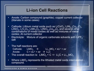
Electrochemical Equations
•Ecell = Eox + Ered
•Wmax = -n*F*Ecell = ΔG
•-n*F*Eocell = ΔGo298
•For a reaction to occur spontaneously, ΔG should be negative (implies that E should be always positive).
•Nernst Equation:
•Ecell = Eocell – (RT/nF)*ln(Q)
•For the following reaction,
•aA(g) + bB (g) cC (g) + dD (g)
•Q = reaction quotient = [PC]x[PD]y / [PA]m[PB]n
J. Jeevarajan, Ph.D.](https://image.slidesharecdn.com/powergoalsforhumanspaceexploration-141005181352-conversion-gate02/85/Power-goals-for-human-space-exploration-6-320.jpg)
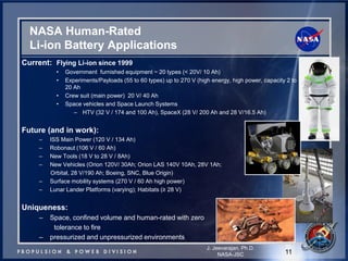
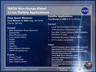
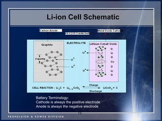
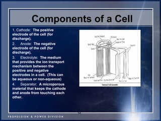
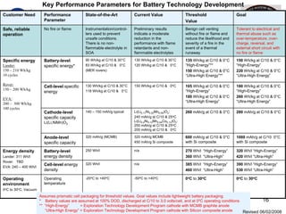

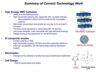
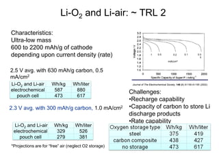
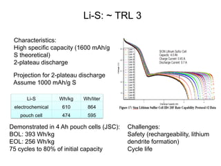
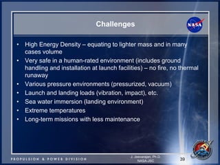


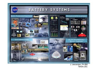

This document discusses power goals for human space exploration and battery technologies. It provides an overview of battery basics, commonly used battery chemistries for space exploration, and technology programs to achieve power goals. The document outlines performance parameters for battery technology development, including specific energy, energy density, operating environment, and specific capacity goals for cathodes and anodes. It also summarizes NASA's lithium-ion battery development efforts for both human-rated and non-human-rated applications in areas like the International Space Station, rovers, satellites, and deep space missions.


