Download to read offline
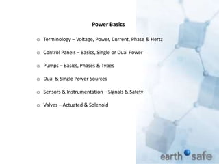
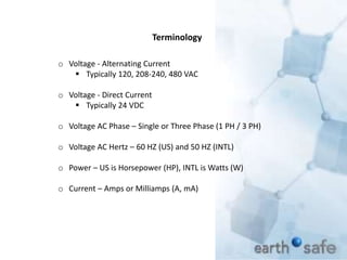
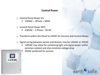
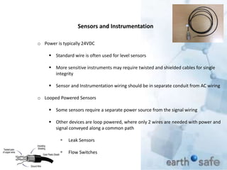

This document provides an overview of power basics for technician training, including terminology, control panels, pumps, power sources, sensors, instrumentation, and valves. It discusses typical voltage standards for North America and internationally, control panel configurations, pump power requirements, dual power source management, sensor signal types and intrinsic safety, and actuated versus solenoid valve operation.


