Download to read offline


![Thermal Magnetic Circuit Breakers
Energy-limiting design — protects downstream components better
than conventional breakers during short circuits
Field-mountable options for selective applications
IP2x Finger-Protection (Front)
North America certifications: UL 489, CSA C22.2 No. 5
International standards: CE Marked, and IEC (VDE) standards for
worldwide acceptance
Ratings: UL/CSA — max. 480Y/277V AC – up to 14 kA interrupt
rating;
IEC — max. 240/415V AC – 15 000 A interrupt rating
48V DC rating, 96V DC — 2-pole series
A positively trip-free mechanism (breaker operation cannot be
defeated by holding the handle in the ON position)
Trip curves: C and D
Time delay (D Characteristic) for high inrush currents during inductive
start-ups such as motors, transformers and power supplies
Superior shock and vibration resistance capabilities — helps to
prevent nuisance tripping
Mounts on DIN Rail
Wire connect, line and load (reversible)
Optional terminals for ring lug terminals
Bulletin 1489-A Circuit Breakers
Industrial Circuit Breakers for North American Applications
UL 489, CSA C22.2 No. 5
240V AC 0.5...40 A
480V/277V AC 0.5...32 A
Miniature Circuit Breaker for EN/IEC Applications
EN/IEC 60947-2
415V AC 0.5...40 A
SWD (0.5...20 A) Switching Duty for fluorescent lighting
applications
HACR
1-pole 48V DC 0.5…40 A
2-pole (series) 96V DC 0.5…40 A
48V DC 0.5…40 A
The Bulletin 1489-A line includes:
Standards Compliance
Certifications
Features
Designed manufactured and listed to UL 489 (CSA 22.2 No. 5)
Thermal-magnetic protection
All ratings are HACR rated
up to 14 kA Interrupting rating
Finger–safe design (front)
DIN Rail mounting
Line and load wire connections
Optional ring terminal connections (convertible)
Description
Bulletin 1489-A Circuit Breakers for Branch Circuit protection are
available in 1-, 2-, and 3-pole construction and are rated 0.5...40 A
at 240V AC and 0.5...32 A at 480Y/277V AC for North American
applications (UL 489 and CSA C22.2 No. 5). The circuit breakers
also have a 1-pole 48V DC, 2-pole (series) 96V DC rating. For
ENIEC applications the products are rated 415V AC, 48V AC
0.5...40 A.
UL 489
CSA C22.2 No. 5
EN/IEC 60947-2
UL Listed
CSA Certified
CE Marked
VDE Certified
The Bulletin 1489-A Thermal Magnetic Circuit Breakers are general-
purpose devices suitable for the majority of industrial, inverse time
circuit breaker applications.
They combine thermal and magnetic trip actions and provide
accurate overload and short-circuit protection for conductors and
connected equipment.
Circuit Breaker Application Information
Selection of a Bulletin 1489 circuit breaker with appropriate circuit
protection includes consideration of:
Circuit Voltage
Circuit Frequency
Available Short Circuit Current
Continuous Current Rating
Application Considerations
Special Operating Conditions
The following discussion is based upon National Electric Code and
UL requirements. Similar considerations are appropriate for
Canadian applications.
Circuit Voltage
The Bulletin 1489-A circuit breakers are rated by voltage class.
Applications should not exceed the listed voltage and current range
(see Table 1).
Circuit Frequency
The Bulletin 1489-A circuit breakers may be applied to frequencies
of 50 Hz and 60 Hz without derating. For applications above 60 Hz,
contact Rockwell Automation with specific application information
for the derating of the circuit breakers.
Available Short Circuit Current
The Bulletin 1489-A circuit breakers should only be applied in those
applications in which the available short-circuit (or fault) current is
less than or equal to 10 kA...14 kA (US/Canada) and 15 kA (IEC).
Table 1. Voltage and Current Ranges
Region Max. Voltage Current Range [A]
EN/IEC Regions
415V AC 0.5...40
48V DC 0.5...40
North America (UL 489
& CSA C22.2 No. 5)
240V AC 0.5...40
480Y/277V AC 0.5...32
1-pole 48V DC 0.5...40
2-pole 96V DC 0.5...40
Overview/Description
Visit our website: www.ab.com/catalogs
Publication 1489-SG001D-EN-P 3
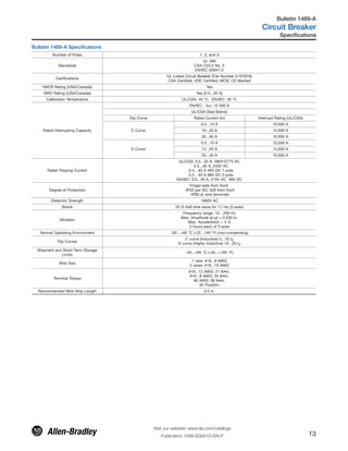
Bulletin 1489-A
Circuit Breaker
Table of Contents
Specifications.............. 13
Description................... 3
Product Selection...... 9
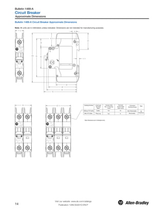
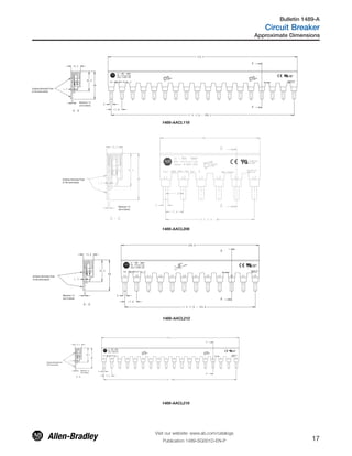
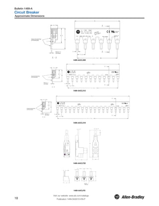
Approximate
Dimensions................... 14](https://image.slidesharecdn.com/1489seriescircuitbreakerguide-190412034423/85/1489-series-circuit-breaker-guide-3-320.jpg)
![Far less damage at the location of the short circuit.
Fast electric separation of a faulty unit from the system, especially
power supplies connected in parallel that are switched off when
the voltage of the power bus drops below a certain level.
Far less wear on the miniature circuit breaker itself. This means
more safe interruptions.
Better protection of all components in the short circuit path.
Far wider range of selective action when used with an upstream
protective device. (No nuisance shut downs from feeder line
interruptions, causing a blackout in all connected branches.)
The following values are applicable to the whole product range with
frequency of 50/60 Hz.
The values were derived from worst case V AC testing of:
D trip 40 A, 240V AC @ 10 kA
D trip 32 A, 480Y/277V AC @ 10 kA
D trip 20 A, 480Y/277V AC @ 14 kA
Current-Limiting at 240V / 10 kA1p, 2p, 3p I²t = 43 kA²s and Ipeak
= 6.2 kA
Current-Limiting at 480Y/277V / 10 kA 1p, 2p, 3p I²t = 60 kA²s and
Ipeak = 6.2 kA
Current-Limiting at 480Y/277V / 14 kA 1p, 2p, 3p I²t = 65 kA²s and
Ipeak = 7.5 kA
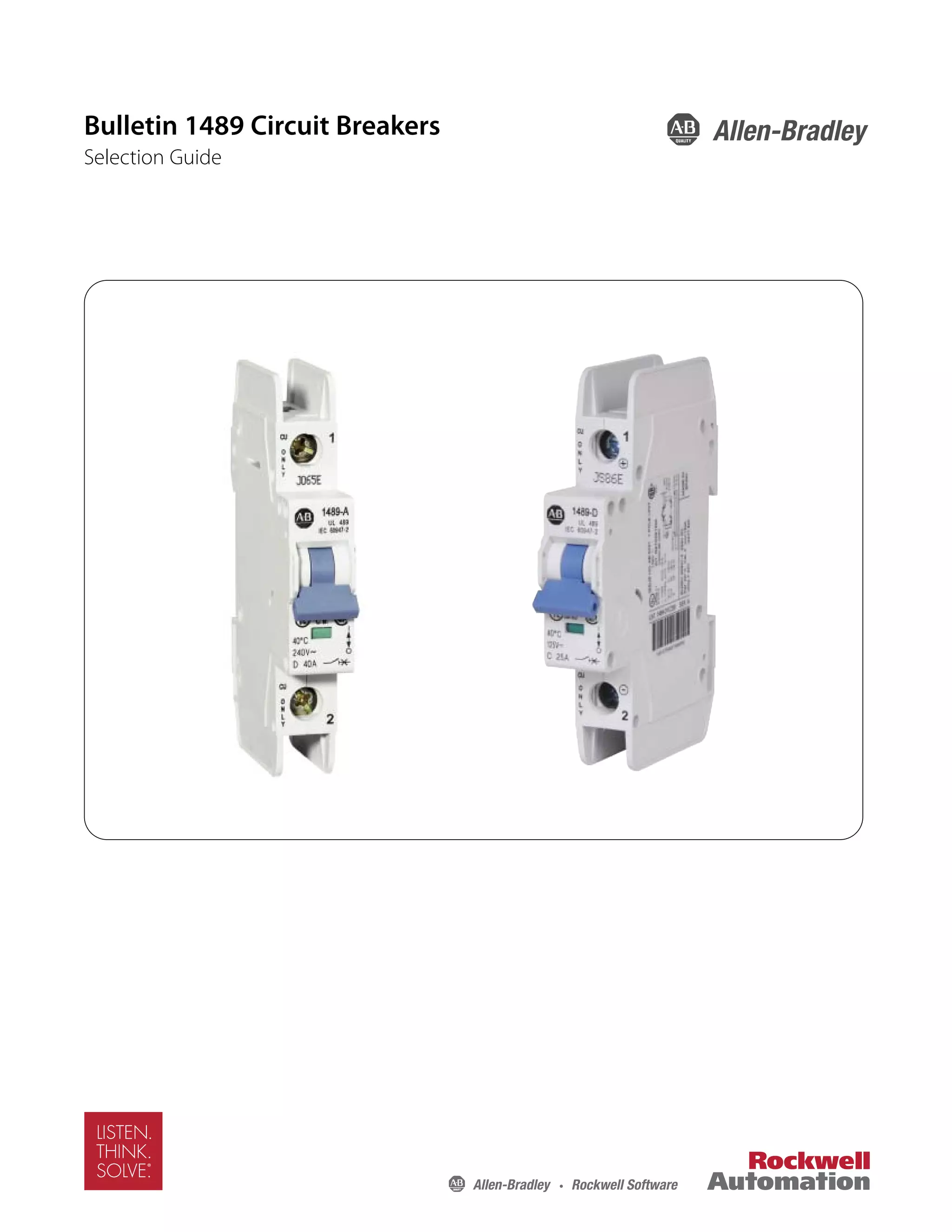
Bulletin 1489-A Ambient Temperature Derating
The standard tripping characteristic for Bulletin 1489-A is Type C.
Type C has a magnetic trip activated at 5…10 times the rated
current of the circuit breaker. The reference temperature for the
thermal tripping characteristics is 40 °C. The Type C characteristic
will suit most applications.
In rare occurrences when the Type C characteristic does not fully
meet the application, the following additional magnetic trip
characteristic is available:
Type D allows for transients approximately twice as high as the
standard Type C.
Use the following table and graph to determine the current rating for
the breaker if the ambient is significantly different than 40 °C.
Bulletin 1489-A Ambient Temperature Derating
Calibration Temperature 40º C (UL)
Application below 0º C is for non-condensing
atmosphere
DeviceMarkedCurrentRating
[A]@40°C
Ambient Temperature (°C)
-25 -20 -10 0 10 20 30 35 40 45 50 55
0.5 0.6 0.6 0.6 0.6 0.6 0.5 0.5 0.5 0.50 0.5 0.5 0.5
1.0 1.3 1.2 1.2 1.2 1.1 1.1 1.0 1.0 1.0 1.0 1.0 0.9
1.5 1.9 1.9 1.8 1.7 1.7 1.6 1.6 1.5 1.5 1.5 1.4 1.4
2.0 2.5 2.5 2.4 2.3 2.2 2.2 2.1 2.0 2.0 2.0 1.9 1.9
3.0 3.8 3.7 3.6 3.5 3.4 3.2 3.1 3.1 3.0 2.9 2.9 2.8
4.0 5.0 5.0 4.8 4.6 4.5 4.3 4.2 4.1 4.0 3.9 3.8 3.8
5.0 6.3 6.2 6.0 5.8 5.6 5.4 5.2 5.1 5.0 4.9 4.8 4.7
6.0 7.5 7.4 7.2 7.0 6.7 6.5 6.2 6.1 6.0 5.9 5.8 5.6
7.0 8.8 8.7 8.4 8.1 7.8 7.6 7.3 7.1 7.0 6.9 6.7 6.6
8.0 10.0 9.9 9.6 9.3 9.0 8.6 8.3 8.2 8.0 7.8 7.7 7.5
10.0 12.6 12.4 12.0 11.6 11.2 10.8 10.4 10.2 10 9.8 9.6 9.4
13.0 16.3 16.1 15.6 15.1 14.6 14.0 13.5 13.3 13 12.7 12.5 12.2
15.0 18.8 18.6 18.0 17.4 16.8 16.2 15.6 15.3 15 14.7 14.4 14.1
16.0 20.1 19.8 19.2 18.6 17.9 17.3 16.6 16.3 16 15.7 15.4 15.0
20.0 25.1 24.8 24.0 23.2 22.4 21.6 20.8 20.4 20 19.6 19.2 18.8
25.0 31.4 31.0 30.0 29.0 28.0 27.0 26.0 25.5 25 24.5 24.0 23.5
30.0 37.7 37.2 36.0 34.8 33.6 32.4 31.2 30.6 30 29.4 28.8 28.2
32.0 40.2 39.7 38.4 37.1 35.8 34.6 33.3 32.6 32 31.4 30.7 30.1
40.0 43.9 43.4 42.0 40.6 39.2 37.8 36.4 35.7 35 34.3 33.6 32.9
Care should be taken for application below 0 °C. These devcies are not
certified to operate correctly in the presence of ice.
All other specifications for standard Bulletin 1489-A products remain
unchanged.
The ambient temperature derating applies to applications of the device as an
IEC Miniature Circuit Breaker (MCB), following 60 947-2 and as Circuit
Breaker to UL489/CSA 22.2 No 5..
Ambient temperature refers to the free air temperature in contact with the
1489 device
Description, Continued
Visit our website: www.ab.com/catalogs
Publication 1489-SG001D-EN-P 5
Bulletin 1489-A
Circuit Breaker](https://image.slidesharecdn.com/1489seriescircuitbreakerguide-190412034423/85/1489-series-circuit-breaker-guide-5-320.jpg)
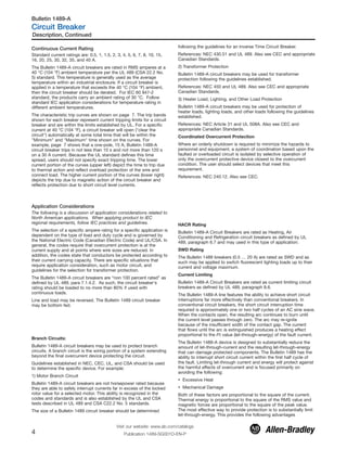
![Ambient Temperature Graph
1.40
1.30
1.20
1.10
1.00
0.90
-20 -10 0 10 20 30 40 50
Ambient Temperature T [°C]
Maximum load I at Ambient Temperature T:L
LI (T) = I K (T)Tn
LoadFactorK[I/I]Tn
Influence of Ambient Temperature (T)
on Load-Carrying Capacity
The 1489-A circuit breaker can function over a wide temperature range
(-30°...+60 °C). Operation in ambient temperatures below 0 °C is based
on a non condensing atmosphere (no ice). Use the graph above or
contact your local Rockwell Automation sales office or Allen-Bradley
distributor to determine the correction factor based upon ambient
Terminals
Standard wire (cable) connection
The standard configuration of the Bulletin 1489-A is with terminals
suitable for connection of stranded copper wire of the wire size #18
… 8 AWG (1.0 … 10 mm2). Strip length for the termination is 0.5
in. (12 mm). Terminals are shipped in the open position for ease of
installation.
Optional Ring Termination
For the Bulletin 1489-A circuit breakers, an optional terminal
configuration (suffix R) is available for use with a ring terminal. This
configuration is shipped so that the terminal screw may be
unscrewed and withdrawn for the insertion of the ring terminal at
proper connection point. The screw is then retightened to provide
proper wire termination.
This unique terminal may be field converted to open the wire
termination to allow standard wire termination of the converted
terminal.
Bus Bars
For the Bulletin 1489-A circuit breakers, UL Recognized bus bars
and UL Listed feeder terminals are available for group connection of
circuit breakers. They are available in 1-, 2-, and 3- pole
configurations for connection of multiple circuit breakers.
Lock-out Attachment
A sturdy lock-out attachment may be added to a circuit breaker.
This lock-out may be padlocked so that the circuit breaker is locked
in the off position.
Shunt Trip
A shunt trip may be added to a circuit breaker to allow the device to
be tripped from a remote source. One version is for tripping
voltages of 12…110V AC (12…60V DC) and another for tripping
voltages of 110…415V AC (110…230V DC).
Auxiliary Contacts
An auxiliary contact module may be added to a circuit breaker to
provide pilot duty contacts to indicate the position of circuit breaker,
off or on. This contact changes state when the circuit breaker is
operated either manually or electrically.
Signal Contacts
A signal/auxiliary contact module may be added to a circuit breaker
to provide auxiliary contact information off and on and signal
contact pilot duty contacts. With signal contacts, the contacts
change state only when the circuit breaker changes state from On
to Off because of an electrical operation. The module contains one
signal contact, form C contact (N.O. and N.C contact with common)
and one auxiliary contact (N.O. and N.C contact with common).
Description, Continued
Visit our website: www.ab.com/catalogs
Publication 1489-SG001D-EN-P6
Bulletin 1489-A
Circuit Breaker](https://image.slidesharecdn.com/1489seriescircuitbreakerguide-190412034423/85/1489-series-circuit-breaker-guide-6-320.jpg)
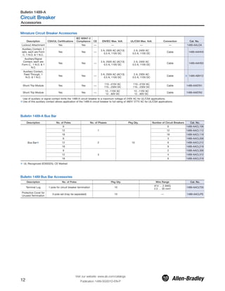
![Time-Current Characteristic Bulletin 1489
Type C and D
Ambient Temperature 40 °C
C D
3
acc. to UL 489
Tripping characteristic
Type D: 10 I : t > 0.1 s
Type C: 5 I : t > 0.1 s
Conventional tripping current
Conventional non-tripping current
20 I : t < 0.1 s
10 I : t < 0.1 s
2.0 I : t = 12- 120 s (T=25 °C)
I = 1.35 I : t < 1 h (T=25 °C)
I = 1.0 I (T=40 °C)
3 N
5
4
N
N
N
N
nt
t
2
1
N
N
2
1
3
4 5
4 5
instantaneous tripping
acc. to IEC 60898-1
1 2 3 4 5 6 7 8 9 10 15 20 30 40 50
0.001
0.002
0.01
0.005
0.02
0.05
0.1
0.2
0.5
1
2
5
10
30
60
120
300
600
1200
3600
7200
I / I N
t[sec]
0.0005
Description, Continued
Visit our website: www.ab.com/catalogs
Publication 1489-SG001D-EN-P 7
Bulletin 1489-A
Circuit Breaker](https://image.slidesharecdn.com/1489seriescircuitbreakerguide-190412034423/85/1489-series-circuit-breaker-guide-7-320.jpg)
![Bulletin 1489 Cat. No. Explanation
Examples given in this section are for reference purposes. This basic explanation should not be used for product selection; not all
combinations will produce a valid catalog number.
1489 - A 1 C 005 R
a b c d e
b
Poles
Code Description
1 1-Pole
2 2-Pole
3 3-Pole
c
Trip Curve
Code Trip Curve
B Trip Curve B
C Trip Curve C
D Trip Curve D
d
Rated Current (In)
Code Current [A]
005 0.5
010 1
015 1.5
020 2
030 3
040 4
050 5
060 6
070 7
080 8
100 10
130 13
150 15
160 16
200 20
250 25
300 30
320 32
350 35
400 40
e
Factory Modifications
Code Description
blank Standard Terminal
R Ring Terminal
Catalog Number Explanation
Visit our website: www.ab.com/catalogs
Publication 1489-SG001D-EN-P8
Bulletin 1489-A
Circuit Breaker
a
Body Style
Code Description
A Standard configuration, AC Device
D Standard configuration, DC Device](https://image.slidesharecdn.com/1489seriescircuitbreakerguide-190412034423/85/1489-series-circuit-breaker-guide-8-320.jpg)
![No. of Poles EN/IEC Maximum Voltage Trip Curve UL/CSA Max. Volt. Rated Current [A]
Standard Wire
Configuration Cat. No.
Ring Terminal
Configuration Cat. No.
1
415V AC,
48V DC
C
277V AC, 48V DC
0.5 1489-A1C005 1489-A1C005R
1 1489-A1C010 1489-A1C010R
1.5 1489-A1C015 1489-A1C015R
2 1489-A1C020 1489-A1C020R
3 1489-A1C030 1489-A1C030R
4 1489-A1C040 1489-A1C040R
5 1489-A1C050 1489-A1C050R
6 1489-A1C060 1489-A1C060R
7 1489-A1C070 1489-A1C070R
8 1489-A1C080 1489-A1C080R
10 1489-A1C100 1489-A1C100R
13 1489-A1C130 1489-A1C130R
15 1489-A1C150 1489-A1C150R
16 1489-A1C160 1489-A1C160R
20 1489-A1C200 1489-A1C200R
25 1489-A1C250 1489-A1C250R
30 1489-A1C300 1489-A1C300R
32 1489-A1C320 1489-A1C320R
240V AC, 48V DC
35 1489-A1C350 1489-A1C350R
40 1489-A1C400 1489-A1C400R
D
277V AC, 48V DC
0.5 1489-A1D005 1489-A1D005R
1 1489-A1D010 1489-A1D010R
1.5 1489-A1D015 1489-A1D015R
2 1489-A1D020 1489-A1D020R
3 1489-A1D030 1489-A1D030R
4 1489-A1D040 1489-A1D040R
5 1489-A1D050 1489-A1D050R
6 1489-A1D060 1489-A1D060R
7 1489-A1D070 1489-A1D070R
8 1489-A1D080 1489-A1D080R
10 1489-A1D100 1489-A1D100R
13 1489-A1D130 1489-A1D130R
15 1489-A1D150 1489-A1D150R
16 1489-A1D160 1489-A1D160R
20 1489-A1D200 1489-A1D200R
25 1489-A1D250 1489-A1D250R
30 1489-A1D300 1489-A1D300R
32 1489-A1D320 1489-A1D320R
240V AC, 48V DC
35 1489-A1D350 1489-A1D350R
40 1489-A1D400 1489-A1D400R
Product Selection
Bulletin 1489-A AC Miniature Circuit Breakers
Bulletin 1489 1-Pole AC Miniature Circuit Breakers
Product Selection
Visit our website: www.ab.com/catalogs
Publication 1489-SG001D-EN-P 9
Bulletin 1489-A
Circuit Breaker](https://image.slidesharecdn.com/1489seriescircuitbreakerguide-190412034423/85/1489-series-circuit-breaker-guide-9-320.jpg)
![Bulletin 1489-A 2-Pole AC Miniature Circuit Breakers
No. of Poles
EN/IEC Maximum
Voltage Trip Curve UL/CSA Max. Volt. Rated Current [A]
Standard Wire Terminal
Cat. No.
Ring Terminal
Configuration Cat. No.
2 415V AC
C
480Y/277V AC, 96V DC
0.5 1489-A2C005 1489-A2C005
1 1489-A2C010 1489-A2C010R
1.5 1489-A2C015 1489-A2C015R
2 1489-A2C020 1489-A2C020R
3 1489-A2C030 1489-A2C030R
4 1489-A2C040 1489-A2C040R
5 1489-A2C050 1489-A2C050R
6 1489-A2C060 1489-A2C060R
7 1489-A2C070 1489-A2C070R
8 1489-A2C080 1489-A2C080R
10 1489-A2C100 1489-A2C100R
13 1489-A2C130 1489-A2C130R
15 1489-A2C150 1489-A2C150R
16 1489-A2C160 1489-A2C160R
20 1489-A2C200 1489-A2C200R
25 1489-A2C250 1489-A2C250R
30 1489-A2C300 1489-A2C300R
32 1489-A2C320 1489-A2C320R
240V AC, 96V DC
35 1489-A2C350 1489-A2C350R
40 1489-A2C400 1489-A2C400R
D
480Y/277V AC, 96V DC
0.5 1489-A2D005 1489-A2D005R
1 1489-A2D010 1489-A2D010R
1.5 1489-A2D015 1489-A2D015R
2 1489-A2D020 1489-A2D020R
3 1489-A2D030 1489-A2D030R
4 1489-A2D040 1489-A2D040R
5 1489-A2D050 1489-A2D050R
6 1489-A2D060 1489-A2D060R
7 1489-A2D070 1489-A2D070R
8 1489-A2D080 1489-A2D080R
10 1489-A2D100 1489-A2D100R
13 1489-A2D130 1489-A2D130R
15 1489-A2D150 1489-A2D150R
16 1489-A2D160 1489-A2D160R
20 1489-A2D200 1489-A2D200R
25 1489-A2D250 1489-A2D250R
30 1489-A2D300 1489-A2D300R
32 1489-A2D320 1489-A2D320R
240V AC, 96V DC
35 1489-A2D350 1489-A2D350R
40 1489-A2D400 1489-A2D400R
Product Selection
Visit our website: www.ab.com/catalogs
Publication 1489-SG001D-EN-P10
Bulletin 1489-A
Circuit Breaker](https://image.slidesharecdn.com/1489seriescircuitbreakerguide-190412034423/85/1489-series-circuit-breaker-guide-10-320.jpg)
![No. of Poles
EN/IEC Maximum
Voltage Trip Curve UL/CSA Max. Volt. Rated Current [A]
Standard Wire Terminal
Cat. No.
Ring Terminal
Configurations Cat. No.
3 415V AC
C
480Y/277V AC
0.5 1489-A3C005 1489-A3C005R
1 1489-A3C010 1489-A3C010R
1.5 1489-A3C015 1489-A3C015R
2 1489-A3C020 1489-A3C020R
3 1489-A3C030 1489-A3C030R
4 1489-A3C040 1489-A3C040R
5 1489-A3C050 1489-A3C050R
6 1489-A3C060 1489-A3C060R
7 1489-A3C070 1489-A3C070R
8 1489-A3C080 1489-A3C080R
10 1489-A3C100 1489-A3C100R
13 1489-A3C130 1489-A3C130R
15 1489-A3C150 1489-A3C150R
16 1489-A3C160 1489-A3C160R
20 1489-A3C200 1489-A3C200R
25 1489-A3C250 1489-A3C250R
30 1489-A3C300 1489-A3C300R
32 1489-A3C320 1489-A3C320R
240V AC
35 1489-A3C350 1489-A3C350R
40 1489-A3C400 1489-A3C400R
D
480Y/277V AC
0.5 1489-A3D005 1489-A3D005R
1 1489-A3D010 1489-A3D010R
1.5 1489-A3D015 1489-A3D015R
2 1489-A3D020 1489-A3D020R
3 1489-A3D030 1489-A3D030R
4 1489-A3D040 1489-A3D040R
5 1489-A3D050 1489-A3D050R
6 1489-A3D060 1489-A3D060R
7 1489-A3D070 1489-A3D070R
8 1489-A3D080 1489-A3D080R
10 1489-A3D100 1489-A3D100R
13 1489-A3D130 1489-A3D130R
15 1489-A3D150 1489-A3D150R
16 1489-A3D160 1489-A3D160R
20 1489-A3D200 1489-A3D200R
25 1489-A3D250 1489-A3D250R
30 1489-A3D300 1489-A3D300R
32 1489-A3D320 1489-A3D320R
240V AC
35 1489-A3D350 1489-A3D350R
40 1489-A3D400 1489-A3D400R
Bulletin 1489-A 3-Pole AC Miniature Circuit Breakers
Product Selection
Visit our website: www.ab.com/catalogs
Publication 1489-SG001D-EN-P 11
Bulletin 1489-A
Circuit Breaker](https://image.slidesharecdn.com/1489seriescircuitbreakerguide-190412034423/85/1489-series-circuit-breaker-guide-11-320.jpg)
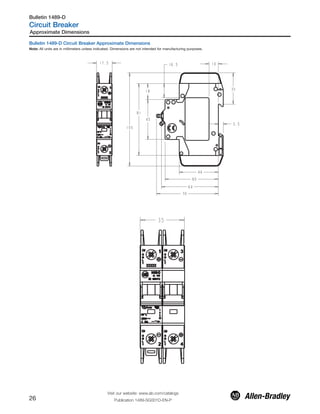
![Bulletin 1489-D Circuit Breakers
Standards Compliance
UL 489
CSA C22.2 No. 5
EN/IEC 60947-2
Certifications
UL Listed
CSA Certified
CE Marked
Features
Designed manufactured and listed to UL 489 (CSA 22.2 No. 5)
Thermal-magnetic protection
up to 10 kA Interrupting rating
Finger–safe design (front)
DIN Rail mounting
Line and load wire connections
Follow polarity requirements
Specially designed for higher voltage DC circuits with a permanent
magnet to direct the arc into the arc splitters.
Field-mountable options for selective applications
IP2x Finger-Protection (Front)
North America certifications: UL 489, CSA C22.2 No. 5
International standards: CE Marked for IEC 60947-2 standards for
worldwide acceptance
10 kA interrupt rating
UL/CSA — 1 pole: max. 125V DC, 2 pole: max. 250V DC
IEC — 1 pole: max. 250V DC, 2 pole: max. 500V DC
A positively trip-free mechanism (breaker operation cannot be
defeated by holding the handle in the ON position)
Trip curves: C
Superior shock and vibration resistance capabilities — helps to
prevent nuisance tripping
Mounts on DIN Rail
Wire connect, follow polarity requirements
Industrial Circuit Breakers for North American Applications
Field mountable options for selective applications
IP2x Finger-Protection (Front)
North America certifications: UL 489, CSA 22.2 No. 5
International standards: CE Marked for IEC 60947-2 standards for
worldwide acceptance
10 kA interrupt rating
UL/CSA — 1 pole: max. 125V DC, 2 pole: max. 250V DC
IEC — 1 pole: max. 250V DC, 2 pole: max. 500V DC
A positively trip-free mechanism (breaker operation cannot be
defeated by holding the handle in the ON position)
Trip curves: C
Superior shock and vibration resistance capabilities — helps to
prevent nuisance tripping
Mounts on DIN Rail
Wire connect, line and load (reversible)
Follow polarity requirements.
UL 489, CSA C22.2 No. 5
1 pole, 125V DC, 2...40 A
2 pole, 250V DC, 2...40 A
Miniature Circuit Breaker for EN/IEC Applications
EN/IEC 60947-2
1 pole, 250V DC, 2...40 A
2 pole, 500V DC, 2...40 A
The Bulletin 1489-D line includes:
Description
Bulletin 1489-D Circuit Breakers for Branch Circuit protection are
available in 1- and 2-pole construction and are rated 2...40 A at
125V DC and 2...40 A at 250V DC for North American applications
(UL 489 and CSA C22.2 No. 5). . For ENIEC applications the
products are rated 1-pole: 2...40 A, 250V DC, and 2-pole: 2...40 A,
500V DC.
Thermal Magnetic Circuit Breakers
The Bulletin 1489-D Thermal Magnetic Circuit Breakers are general-
purpose devices suitable for the majority of industrial, inverse time
circuit breaker applications.
They combine thermal and magnetic trip actions and provide
accurate overload and short-circuit protection for conductors and
connected equipment.
Circuit Breaker Application Information
Selection of a Bulletin 1489-D circuit breaker with appropriate circuit
protection includes consideration of:
Circuit Voltage
Available Short Circuit Current
Continuous Current Rating
Application Considerations
Special Operating Conditions
Regional Certifications
The following discussion is based upon National Electric Code and
UL requirements. Similar considerations are appropriate for
Canadian and IEC applications.
Circuit Voltage
The Bulletin 1489-D circuit breakers are rated by voltage class.
Applications should not exceed the listed voltage and current range
(see Table 1).
Available Short Circuit Current
The Bulletin 1489-D circuit breakers should only be applied in those
applications in which the available short-circuit (or fault) current is
less than or equal to 10 kA.
Table 1. Voltage and Current Ranges
Region Max. Voltage
Current Range
[A]
EN/IEC Regions
1-pole 250V DC 2...40
2-pole 500V DC 2...40
North America
(UL 489 & CSA
C22.2 No. 5)
1-pole 125V DC 2...40
2-pole 250V DC 2...40
Visit our website: www.ab.com/catalogs
Publication 1489-SG001D-EN-P 19
Bulletin 1489-D
Circuit Breaker
Overview/Description
Table of Contents
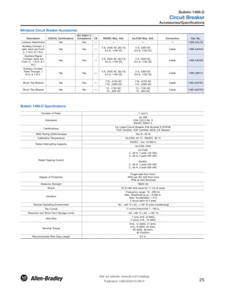
Specifications.............. 25
Description................... 19
Product Selection...... 24
Approximate
Dimensions................... 26](https://image.slidesharecdn.com/1489seriescircuitbreakerguide-190412034423/85/1489-series-circuit-breaker-guide-19-320.jpg)
![Continuous Current Rating
Standard current ratings are: 2, 3, 4, 5, 6, 7, 8, 10, 15, 16, 20, 25,
30, 32, 35, and 40 A.
The Bulletin 1489-D circuit breakers are rated in amperes at a 40 °C
(104 °F) ambient temperature per the UL 489 (CSA 22.2 No. 5)
standard. This temperature is generally used as the average
temperature within an industrial enclosure. If a circuit breaker is
applied in a temperature that exceeds the 40 °C (104 °F) ambient,
then the circuit breaker should be derated. For IEC 60 947-2
standard, the products carry an ambient rating of 30 °C. Follow
standard IEC application considerations for temperature rating in
different ambient temperatures.
The characteristic trip curve is shown on page 22. The trip bands
shown for each breaker represent current tripping limits for a circuit
breaker and are within the limits established by UL. For a specific
current at 40 °C (104 °F), a circuit breaker will open ("clear the
circuit") automatically at some total time that will be within the
"Minimum" and "Maximum" time shown on the curves. For
example, page 21 shows that a one-pole, 15 A, Bulletin 1489 circuit
breaker trips in not less than 10 s and not more than 120 s on a 30
A current. Because the UL standard defines this time spread, users
should not specify exact tripping time. The lower current portion of
the curves (upper left) depict the time to trip due to thermal action
and reflect overload protection of the wire and connect load. The
higher current portion of the curves (lower right) depicts the trip due
to magnetic action of the circuit breaker and reflects protection due
to short circuit level currents.
Application Considerations
The following is a discussion of application considerations related to
North American applications. When applying product to IEC
regional requirements, follow IEC practices and guidelines.
The selection of a specific ampere rating for a specific application is
dependent on the type of load and duty cycle and is governed by
the National Electric Code (Canadian Electric Code) and UL/CSA. In
general, the codes require that overcurrent protection is at the
current supply and at points where wire sizes are reduced. In
addition, the codes state that conductors be protected according to
their current carrying capacity. There are specific situations that
require application consideration, such as motor circuit, and
guidelines for the selection for transformer protection.
The Bulletin 1489-D circuit breakers are “non 100 percent rated” as
defined by UL 489, para 7.1.4.2. As such, the circuit breaker's
rating should be loaded to no more than 80% if used with
continuous loads.
Determining Ratings
Bulletin 1489-D Ambient Temperature Derating
Calibration Temperature 40º C (UL)
Application below 0º C is for non-condensing
atmosphere
DeviceMarkedCurrent
Rating[A]@40°C
-25 -20 -10 0 10 20 30 35 40 45 50 55
2.0 2.5 2.5 2.4 2.3 2.2 2.2 2.1 2.0 2.0 2.0 1.9 1.9
3.0 3.8 3.7 3.6 3.5 3.4 3.2 3.1 3.1 3.0 2.9 2.9 2.8
4.0 5.0 5.0 4.8 4.6 4.5 4.3 4.2 4.1 4.0 3.9 3.8 3.8
5.0 6.3 6.2 6.0 5.8 5.6 5.4 5.2 5.1 5.0 4.9 4.8 4.7
6.0 7.5 7.4 7.2 7.0 6.7 6.5 6.2 6.1 6.0 5.9 5.8 5.6
7.0 8.8 8.7 8.4 8.1 7.8 7.6 7.3 7.1 7.0 6.9 6.7 6.6
8.0 10.0 9.9 9.6 9.3 9.0 8.6 8.3 8.2 8.0 7.8 7.7 7.5
10.0 12.6 12.4 12.0 11.6 11.2 10.8 10.4 10.2 10 9.8 9.6 9.4
13.0 16.3 16.1 15.6 15.1 14.6 14.0 13.5 13.3 13 12.7 12.5 12.2
15.0 18.8 18.6 18.0 17.4 16.8 16.2 15.6 15.3 15 14.7 14.4 14.1
16.0 20.1 19.8 19.2 18.6 17.9 17.3 16.6 16.3 16 15.7 15.4 15.0
20.0 25.1 24.8 24.0 23.2 22.4 21.6 20.8 20.4 20 19.6 19.2 18.8
25.0 31.4 31.0 30.0 29.0 28.0 27.0 26.0 25.5 25 24.5 24.0 23.5
30.0 37.7 37.2 36.0 34.8 33.6 32.4 31.2 30.6 30 29.4 28.8 28.2
32.0 40.2 39.7 38.4 37.1 35.8 34.6 33.3 32.6 32 31.4 30.7 30.1
40.0 43.9 43.4 42.0 40.6 39.2 37.8 36.4 35.7 35 34.3 33.6 32.9
Care should be taken for application below 0 °C. These devcies are not
certified to operate correctly in the presence of ice.
All other specifications for standard Bulletin 1489-A products remain
unchanged.
The ambient temperature derating applies to applications of the device as an
IEC Miniature Circuit Breaker (MCB), following 60 947-2 and as Circuit
Breaker to UL489/CSA 22.2 No 5..
Ambient temperature refers to the free air temperature in contact with the
1489 device
Description
Visit our website: www.ab.com/catalogs
Publication 1489-SG001D-EN-P20
Bulletin 1489-D
Circuit Breaker
The tripping characteristic for Bulletin 1489-D is Type C. Type C has
a magnetic trip activated at 7…15 times the rated current of the
circuit breaker. The reference temperature for the thermal tripping
characteristics is 40 °C. The Type C characteristic will suit most
applications.
Use the following table and graph to determine the current rating for
the breaker if the ambient is significantly different than 40 °C.
Polarity
Positive and negative connection many not be reversed.
Branch Circuits
Bulletin 1489 circuit breakers may be used to protect branch
circuits. A branch circuit is the wiring portion of a system extending
beyond the final overcurrent device protecting the circuit.
Guidelines established in NEC, CEC, UL, and CSA should be used
to determine the specific device.
Coordinated Overcurrent Protection
Where an orderly shutdown is required to minimize the hazards to
personnel and equipment, a system of coordination based upon the
faulted or overloaded circuit is isolated by selective operation of
only the overcurrent protective device closest to the overcurrent
condition. The user should select devices that meet this
requirement.
References: NEC 240.12. Also see CEC.](https://image.slidesharecdn.com/1489seriescircuitbreakerguide-190412034423/85/1489-series-circuit-breaker-guide-20-320.jpg)
![1.40
1.30
1.20
1.10
1.00
0.90
-20 -10 0 10 20 30 40 50
Ambient Temperature T [°C]
Maximum load I at Ambient Temperature T:L
LI (T) = I K (T)Tn
LoadFactorK[I/I]Tn
Influence of Ambient Temperature (T)
on Load-Carrying Capacity
The 1489-D circuit breaker can function over a wide temperature range
(-30...+60 °C). Operation in ambient temperatures below 0 °C is based on
a non condensing atmosphere (no ice). Use the graph above or contact
your local Rockwell Automation sales office or Allen-Bradley distributor
to determine the correction factor based upon ambient temperature.
Terminals
Standard wire (cable) connection
The standard configuration of the Bulletin 1489 is with terminals
suitable for connection of stranded copper wire of the wire size #18
… 8 AWG (1.0 … 10 mm2). Strip length for the termination is 0.5
in. (12 mm). Terminals are shipped in the open position for ease of
installation.
Lock-out Attachment
A sturdy lock-out attachment may be added to a circuit breaker.
This lock-out may be padlocked so that the circuit breaker is locked
in the off position.
Shunt Trip
A shunt trip may be added to a circuit breaker to allow the device to
be tripped from a remote source. One version is for tripping
voltages of 12…110V AC (12…60V DC) and another for tripping
voltages of 110…415V AC (110…230V DC).
Auxiliary Contacts
An auxiliary contact module may be added to a circuit breaker to
provide pilot duty contacts to indicate the position of circuit breaker,
off or on. This contact changes state when the circuit breaker is
operated either manually or electrically.
Signal Contacts
A signal/auxiliary contact module may be added to a circuit breaker
to provide auxiliary contact information off and on and signal
contact pilot duty contacts. With signal contacts, the contacts
change state only when the circuit breaker changes state from On
to Off because of an electrical operation. The module contains one
signal contact, form C contact (N.O. and N.C contact with common)
and one auxiliary contact (N.O. and N.C contact with common).
Ambient Temperature Graph
Description
Visit our website: www.ab.com/catalogs
Publication 1489-SG001D-EN-P 21
Bulletin 1489-D
Circuit Breaker](https://image.slidesharecdn.com/1489seriescircuitbreakerguide-190412034423/85/1489-series-circuit-breaker-guide-21-320.jpg)
![Time Current Curve – 1- and 2-Pole Circuit Breaker
Time-Current Characteristic UL
0.0005
Trippingtimet[sec]
I / I
7200
3600
1200
600
300
120
60
30
10
5
2
1
0.5
0.2
0.1
0.05
0.02
0.005
0.01
0.002
0.001
03 04 0551 022 3 4 5 6 7 8 9 011
C
1
2
t
nt
4
3
I = 1.0 In
I = 1.35 In : t < 1 h
2.0 In : t = 12 - 120 s
conventional non-tripping current
conventional tripping current
7 In : t > 0.1 s
Tripping Characteristic
acc. to UL 489
15 In : t < 0.1 s
5
4
3
2
3
1
5
Description
Visit our website: www.ab.com/catalogs
Publication 1489-SG001D-EN-P22
Bulletin 1489-D
Circuit Breaker](https://image.slidesharecdn.com/1489seriescircuitbreakerguide-190412034423/85/1489-series-circuit-breaker-guide-22-320.jpg)
![a
Body Style
Code Description
A Standard configuration, AC Device
D Standard configuration, DC Device
b
Poles
Code Description
1 1-Pole
2 2-Pole
c
Trip Curve
Code Trip Curve
C Trip Curve C
d
Rated Current (In)
Code Current [A]
005 0.5
010 1
015 1.5
020 2
030 3
040 4
050 5
060 6
070 7
080 8
100 10
130 13
150 15
160 16
200 20
250 25
300 30
320 32
350 35
400 40
e
Factory Modifications
Code Description
blank Standard Terminal
R
Ring Terminal
(available on 1489-A only)
Bulletin 1489 Cat. No. Explanation
Examples given in this section are for reference purposes. This basic explanation should not be used for product selection; not all
combinations will produce a valid catalog number.
1489 - D 1 C 020
a b c d e
Catalog Number Explanation
Visit our website: www.ab.com/catalogs
Publication 1489-SG001D-EN-P 23
Bulletin 1489-D
Circuit Breaker](https://image.slidesharecdn.com/1489seriescircuitbreakerguide-190412034423/85/1489-series-circuit-breaker-guide-23-320.jpg)
![Product Selection
Bulletin 1489-D, 1-Pole DC Miniature Circuit Breakers
No. of Poles EN/IEC Maximum Voltage Trip Curve UL/CSA Max. Volt. Rated Current [A] Standard Wire Configuration Cat. No.
1 250 C 125 V DC 2 1489-D1C020
1 250 C 125 V DC 3 1489-D1C030
1 250 C 125 V DC 4 1489-D1C040
1 250 C 125 V DC 5 1489-D1C050
1 250 C 125 V DC 6 1489-D1C060
1 250 C 125 V DC 7 1489-D1C070
1 250 C 125 V DC 8 1489-D1C080
1 250 C 125 V DC 10 1489-D1C100
1 250 C 125 V DC 13 1489-D1C130
1 250 C 125 V DC 15 1489-D1C150
1 250 C 125 V DC 16 1489-D1C160
1 250 C 125 V DC 20 1489-D1C200
1 250 C 125 V DC 25 1489-D1C250
1 250 C 125 V DC 30 1489-D1C300
1 250 C 125 V DC 32 1489-D1C320
1 250 C 125 V DC 35 1489-D1C350
1 250 C 125 V DC 40 1489-D1C400
Bulletin 1489-D, 2-Pole AC Miniature Circuit Breakers
No. of Poles EN/IEC Maximum Voltage Trip Curve UL/CSA Max. Volt. Rated Current [A] Standard Wire Configuration Cat. No.
2 500V DC C 250V DC 2 1489-D2C020
2 500V DC C 250V DC 3 1489-D2C030
2 500V DC C 250V DC 4 1489-D2C040
2 500V DC C 250V DC 5 1489-D2C050
2 500V DC C 250V DC 6 1489-D2C060
2 500V DC C 250V DC 7 1489-D2C070
2 500V DC C 250V DC 8 1489-D2C080
2 500V DC C 250V DC 10 1489-D2C100
2 500V DC C 250V DC 13 1489-D2C130
2 500 VDC C 250V DC 15 1489-D2C150
2 500V DC C 250V DC 16 1489-D2C160
2 500V DC C 250V DC 20 1489-D2C200
2 500V DC C 250V DC 25 1489-D2C250
2 500V DC C 250V DC 30 1489-D2C300
2 500V DC C 250V DC 32 1489-D2C320
2 500V DC C 250V DC 35 1489-D2C350
2 500V DC C 250V DC 40 1489-D2C400
Product Selection
Visit our website: www.ab.com/catalogs
Publication 1489-SG001D-EN-P24
Bulletin 1489-D
Circuit Breaker](https://image.slidesharecdn.com/1489seriescircuitbreakerguide-190412034423/85/1489-series-circuit-breaker-guide-24-320.jpg)


The document provides information on Thermal Magnetic Circuit Breakers from Bulletin 1489 and 1489-A. It includes specifications, descriptions, product selection guidance, and application information. Some key details are that the breakers provide overload and short-circuit protection, have DIN rail mounting, optional ring terminals, and ratings of up to 480V AC and 14kA interrupt rating for North America or 415V AC and 15kA for international. They are suitable for general industrial applications that require inverse time circuit breaker protection.