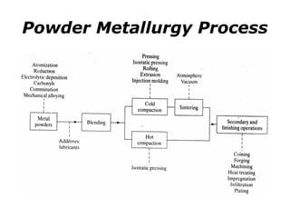
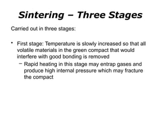
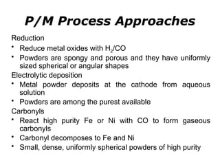
Powder metallurgy (PM) is an ancient and evolving technique for producing metal parts from metallic powders through processes like blending, compaction, and sintering. It offers advantages such as controlled porosity, economical mass production, and the ability to use a wide range of materials, but it also has limitations, including high material and tooling costs. PM is particularly prevalent in automotive applications, with a significant focus on producing reliable, precision components.
![History of Powder
Metallurgy
• IRON Metallurgy >
• How did Man make iron in 3000 BC?
• Did he have furnaces to melt iron air blasts, and
• The reduced material, which would then be
spongy, [ DRI ], used to be hammered to a solid or
to a near solid mass.
• Example: The IRON PILLER at Delhi
• Quite unlikely, then how ???](https://image.slidesharecdn.com/powdermetallurgy1-241109044208-78b9c02e/85/Powder-Metallurgy-1-mechanical-engineering-pptx-11-320.jpg)
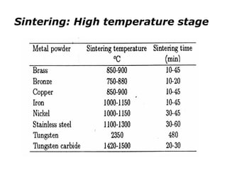
![Powder Metallurgy Merits
o The main constituent need not be melted
o The product is porous - [ note : the porosity can be controlled]
o Constituents that do not mix can be used to make composites, each constituent
retaining its individual property
o Near Nett Shape is possible, thereby reducing the post-production costs,
therefore:
Precision parts can be produced
The production can be fully automated, therefore,
Mass production is possible
Production rate is high
Over-head costs are low
Break even point is not too large
Material loss is small
Control can be exercised at every stage](https://image.slidesharecdn.com/powdermetallurgy1-241109044208-78b9c02e/85/Powder-Metallurgy-1-mechanical-engineering-pptx-17-320.jpg)
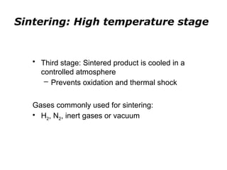
![Powder Metallurgy Disadvantages
o Porous !! Not always desired.
o Large components cannot be produced on
a large scale [Why?]
o Some shapes [such as?] are difficult to be
produced by the conventional p/m route.
• WHATEVER, THE MERITS ARE SO
MANY THAT P/M,
• AS A FORMING TECHNIQUE, IS GAINING
POPULARITY](https://image.slidesharecdn.com/powdermetallurgy1-241109044208-78b9c02e/85/Powder-Metallurgy-1-mechanical-engineering-pptx-18-320.jpg)
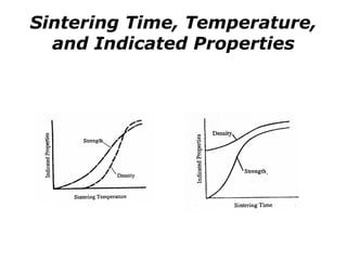
![Powder Metallurgy
• An important point that comes out :
• The entire material need not be melted to fuse it.
• The working temperature is well below the melting
point of the major constituent, making it a very
suitable method to work with refractory materials,
such as: W, Mo, Ta, Nb, oxides, carbides, etc.
• It began with Platinum technology about 4
centuries ago … in those days, Platinum, [mp =
1774°C], was "refractory", and could not be
melted.](https://image.slidesharecdn.com/powdermetallurgy1-241109044208-78b9c02e/85/Powder-Metallurgy-1-mechanical-engineering-pptx-19-320.jpg)