This document presents a study on the development of a collision avoidance driver assistance system using a potential field-based motion planning and control method. The system utilizes a steering control mechanism and direct yaw moment control (DYC) to effectively guide the vehicle away from obstacles in real-time simulations. Results demonstrate that the proposed system can successfully maneuver and avoid collisions without lane departures.
![TELKOMNIKA, Vol.15, No.2, June 2017, pp. 853~860
ISSN: 1693-6930, accredited A by DIKTI, Decree No: 58/DIKTI/Kep/2013
DOI: 10.12928/TELKOMNIKA.v15i2.6132 853
Received February 5, 2017; Revised April 12, 2017; Accepted April 30, 2017
Potential Field Based Motion Planning with Steering
Control and DYC for ADAS
Nurbaiti Wahid*
1
, Hairi Zamzuri
2
, Nurhaffizah Hassan
3
, Mohd Azizi Abdul Rahman
4
1,3
Faculty of Electrical and Engineering, Universiti Teknologi MARA, 23000 Dungun, Terengganu, Malaysia
1,2,3,4
Malaysia Japan International Institute of Technology, Universiti Teknologi Malaysia, 54100 Jalan
Sultan Yahya Petra, Kuala Lumpur, Malaysia
Corresponding author, e-mail: nurbaiti@tganu.uitm.edu.my*
1
, hairi.kl@utm.my
2
,
nurhaffizah@tganu.uitm.edu.my
3
, azizi.kl@utm.my
4
Abstract
In this study, the development of motion planning and control for collision avoidance driver
assistance systems is presented. A potential field approach has been used in formulating the collision
avoidance algorithm based on predicted vehicle motion. Then, to realize the advanced driver assistance
systems (ADAS) for collision avoidance, steering control system and direct yaw moment control (DYC) is
designed to follow the desired vehicle motion. Performance evaluation is conducted in simulation
environment in term of its performance in avoiding the obstacles. Simulation results show that the vehicle
collision avoidance assistance systems can successfully complete the avoidance behavior without
colliding.
Keywords: potential field, motion planning, steering control, DYC, ADAS
Copyright © 2017 Universitas Ahmad Dahlan. All rights reserved.
1. Introduction
Traffic accident prevention and collision avoidance are the critical topic being concerned
in automotive world. Regarding to the statistic given by Polis Diraja Malaysia (PDRM), traffic
accident and fatalities is increasing from year to year [1]. In 2013, the number of traffic accidents
had been increased by 3.1% from 462423 to 477204 compared to 2012. In 2014 the number of
traffic accidents is slightly decreased to 0.21% which contributed to 476196 cases.
Nevertheless, the number of road crashed still retain in a high level. Since decades ago, the
engraving problem caused by traffic accidents had been continually voiced out by global
community. About 1.2 million annual deaths due to traffic accident around the world report by
World Health Organization (WHO) in 2004 proved the problem scale [2, 3]. Therefore, the
development of advanced safety technology as the advanced driver assistance systems (ADAS)
for accident preventions and collision avoidance are essential.
The aim of advances safety technology is to take the surrounding of vehicle
environment into account for collision prevention and reduce the traffic accidents by assist the
driver during critical situation. Collision avoidance systems are one of the vehicle safety
technologies under ADAS group are expected to enhance vehicle safety and reduce collision’s
severity. The successful collision avoidance systems are relied on the sensory system, motion
planning and the actuator manipulation control to complete the avoidance maneuver. The needs
for enhanced collision avoidance systems technology for ground vehicle continuously show
significant challenge for the system efficiency.
Path planning and motion planning of advanced driver assistance systems are the
important software elements used in vehicle navigation for collision avoidance [4]. Generally
motion planning for collision avoidance can be divided into two clasifications which are global
and local path planning [5]. Global path planning refers to the well-known environment while
local path planning is determined if environment is unknown. It also can be classified into off-line
and on-line depending on the obstacle behavior. Off-line motion planning is used to formulate
the case of static obstacle where the route decision is predefined. On the contrary, on-line
motion planning used to map the moving obstacle and the route decision is identified based on
the dynamics environment [6]. There are numerous motion planning techniques had been used](https://image.slidesharecdn.com/416132-200909092600/75/Potential-Field-Based-Motion-Planning-with-Steering-Control-and-DYC-for-ADAS-1-2048.jpg)
![ ISSN: 1693-6930
TELKOMNIKA Vol. 15, No. 2, June 2017 : 853 – 860
854
in automotive vehicle navigation systems for collision avoidance. Motion planning using artificial
potential field was introduced by [7] and had been implemented in robotics field [8, 9] based on
idea in filling the robot workspace with the information from environment. Application of potential
field techniques in motion planning also had been extended into vehicle guidance systems
including lane keeping [10] and obstacle avoidance [11]. In executing the behavior of obstacle
avoidance, the control system is designed to ensure the desired vehicle motion is followed
safely without colliding.
This study presents the motion planning and control system for vehicle collision
avoidance driver assistance systems. The structure of this paper is divided into three main
parts; the second part described the formulation of motion planning to identify the vehicle
desired motion. This part also discussed on the control system designed based on proposed
collision avoidance algorithm to track the desired trajectory. The third part concentrated on the
simulation results of vehicle manuevre behaviour in avoiding the collision for a given driving
scenario. The conclusion and recommendation of future works are given in the final part of this
paper.
2. Collision Avoidance Motion Planning and Control System
This section described the motion planning and control system formulation for collision
avoidance system. In this work, motion planning was formulated using artificial potential field
approach while controller designed for lateral motion control was realized by steering wheel
controller and DYC.
2.1. Vehicle Collision Avoidance System Overview
Figure 1 shows the system overview of driver assistance systems for collision
avoidance. Firstly, the algorithm for collision avoidance was generated to identify desired yaw
rate value, by using potential field approach.
Figure 1. Collision avoidance driver assistance systems overview
2.2. Vehicle Collision Avoidance System Overview
In this work, potential field approach was used for motion planning in generating
collision avoidance algorithm due to mathematical simplicity [12] and minimal computational
effort [13]. The environmental information such as the goal to the target location and obstacle is
represented as attractive and repulsive potential energy respectively [14].
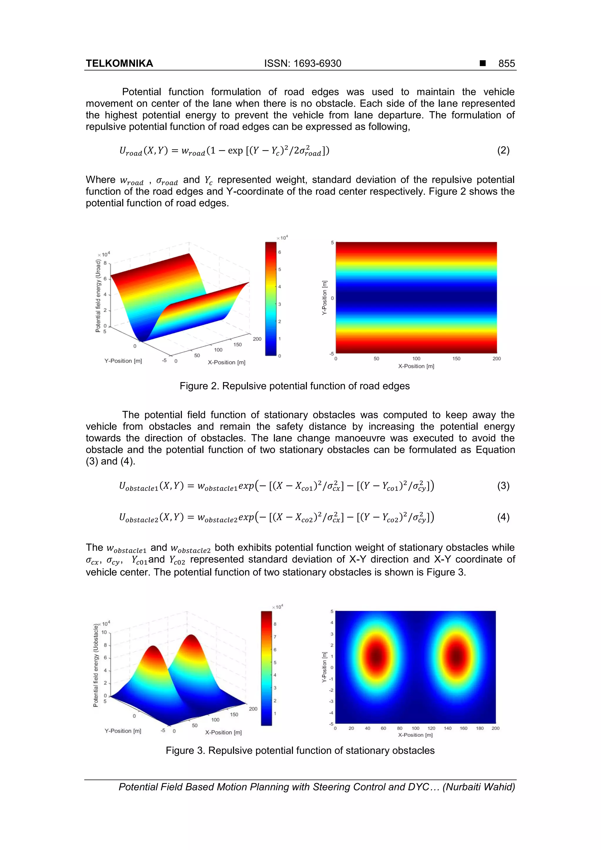
In general, the goal to the target location represented by attractive potential function
used to guide the vehicle to the desired destination. The road edges and the obstacles
represented by repulsive potential function that keep the obstacles far away from the vehicle as
well as to avoid the collision. In this work, the potential field formulation was calculated
regarding to the previous works that had been done in [13-17]. Several potential functions were
formulated for road edges and obstacle based on situation of two stationary obstacles located
on the straight lane. The summation of all potential functions value can be denoted as
Eequation (1).
(1)](https://image.slidesharecdn.com/416132-200909092600/75/Potential-Field-Based-Motion-Planning-with-Steering-Control-and-DYC-for-ADAS-2-2048.jpg)
![ ISSN: 1693-6930
TELKOMNIKA Vol. 15, No. 2, June 2017 : 853 – 860
856
In this work, the parameters of the weight of potential function, , ,
and standard deviation of potential function, , and were used to modify
the shape of potential field energy that represented the road edges and stationary obstacles. By
referring to the equation (1), the total potential field energy map for road edges and obstacles is
illustrated in Figure 4.
Figure 4. Map for total potential field function
In realizing the driver assistance systems, the reference yaw rate value was calculated
to find the optimal performance function for motion planning based on work done in [16, 17].
The application of potential field with optimal control theory as in [16, 17] was implemented to
replace the gradient descent method [11] that generally used in creating the motion planning.
This method was used to avoid the local minima problem that might be existed during the task
execution. The prediction yaw rate value which consists of several yaw rate reference
candidates was computed for the range of and value and can be expressed
as following.
(5)
In this work, the and both was set to -0.5 rad/s and 0.5 rad/s
respectively. The vehicle position prediction value at prediction time horizon and evaluation cost
function of yaw rate reference value can be represented as equation (6) and (7) below:
(6)
(7)
where denoted as vehicle yaw angle. By using application of optimal control theory in [17], the
evaluation cost function for identification of yaw rate reference value can mathematically be
expressed as following equation. The reference yaw rate was defined from the minimum value
of evaluation cost function that was calculated on each sampling time where q specified as
weight of yaw rate prediction.
(8)](https://image.slidesharecdn.com/416132-200909092600/75/Potential-Field-Based-Motion-Planning-with-Steering-Control-and-DYC-for-ADAS-4-2048.jpg)
![TELKOMNIKA ISSN: 1693-6930
Potential Field Based Motion Planning with Steering Control and DYC… (Nurbaiti Wahid)
857
2.3. Control System Formulation
In this work the lateral motion control algorithm was designed which consist of steering
control system and direct yaw moment control. This control strategy was applied in order to
track the vehicle desired motion for collision prevention. The reference steering angle was
determined by using linear single-track vehicle model based on inverse dynamics method in
following the desired path. The state-space represented the linear vehicle model equation can
be expressed as below:
(9)
where,
,
,
By using inverse method and negligible the effect of side slip angle, the steering angle value
can be calculated as in equation (10).
(10)
The desired steering angle was determined by considering the value of steering gear ratio and
can be computed as follows:
(11)
For direct yaw moment control, the corrective yaw moment and corrective distributed torque
both were formulated as equation (12) and (13) respectively based on works in [18, 19].
and referred to corrective yaw moment gain, indicated the tire wheel radius and
denoted as vehicle track width.
+ (12)
(13)
With approximation of vehicle longitudinal motion as one-wheel vehicle model, the longitudinal
force can be identified as following equation where indicated the vehicle running resistance.
(14)
3. Results and Discussion
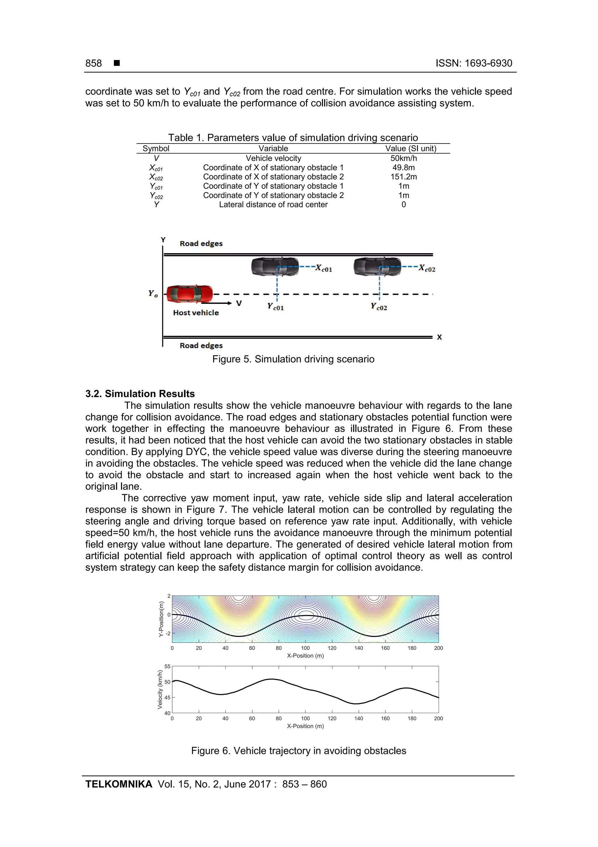
3.1. Simulation Driving Scenario
In the simulation works, the driving scenario was created based on two stationary
obstacles (parking vehicle) located on the straight lane as shown in Figure 5. Additionally,
Table 1 tabulated the parameters value that had been set for the simulation scenario condition.
The parking vehicle, both was located at coordinate Xc01 and Xc02 of vehicle centre where Y-](https://image.slidesharecdn.com/416132-200909092600/75/Potential-Field-Based-Motion-Planning-with-Steering-Control-and-DYC-for-ADAS-5-2048.jpg)
![TELKOMNIKA ISSN: 1693-6930
Potential Field Based Motion Planning with Steering Control and DYC… (Nurbaiti Wahid)
859
Figure 7. Simulation results of vehicle behaviour.
4. Conclusion
In enhancing the performance of active safety, this paper described and studied the
motion planning of vehicle obstacle avoidance driver assistance systems based on artificial
potential field method. Several potential functions had been developed by considering two
stationary obstacles and road edges to describe the risk potential. Lane departure risk potential
and collision with obstacle risk potential was considered for control the lateral motion of host
vehicle. To complete the collision avoidance execution task, the control system had been
formulated based on steering wheel control and DYC. In this work, steering control system was
used to complete the steering avoidance manoeuvre while DYC will give the effect to the vehicle
speed by control the longitudinal motion of host vehicle. The performance evaluation of
proposed collision avoidance driver assistance systems had been investigated through the
simulation environment. From simulation results, it can be revealed that, the proposed driving
assistance systems for collision avoidance can successfully followed the avoidance manoeuvre
with surrounding obstacles. For the future studies, the formulated algorithm can be further
explored and expanded into dynamics vehicle collision avoidance environment considering
moving obstacles with different driving scenarios.
Acknowledgement
This work is funded by Ministry of Higher Education, Malaysia under Research
University Grant, Universiti Teknologi Malaysia (vote no: 13H73) and Perusahaan Otomobil
Nasional (PROTON) Sdn. Bhd (vote no: 4C099). The authors also would like to acknowledge
Assoc. Prof. Pongsathorn Raksincharoensak for the valuable knowledge and Smart Mobility
Research Centre, Tokyo University of Agriculture and Technology (TUAT) for the placement
given during the short-term attachment research programme.
References
[1] Transport Statistic Malaysia 2014. Ministry of Transportation Malaysia. 2015.
[2] Mohd Yusoff MF, Mohamad NA, Md Nor NG. Malaysian Value of Fatal and Non Fatal Injury due to
Road Accident: The Willingness to Pay Using Conjoint Analysis Study. Proceedings of the Eastern
Asia Society for Transportation Studies. 2011; 8: 1–13.
[3] Mohd Yusof MF, Md Nor NG, Mohamad NA. Malaysian Value of Statistical Life for Fatal Injury in Road
Accident: A Conjoint Analysis Approach. Journal of Society for Transportation and Traffic Studies.
2013; 2(2): 30–40.
[4] Hesse T, Sattel T. An Approach to Integrate Vehicle Dynamics in Motion Planning for Advanced Driver
Assistance Systems. IEEE Intelligent Vehicles Symposium. Istanbul. 2007: 1240-1245.
[5] Kamil F, Tang S, Kakhsar W, Zulkifli N, Ahmad SA. A Review on Motion Planning and Obstacle
Avoidance Approaches in Dynamic Environments. Advances in Robotics and Automation. 2015; 4(2).
[6] Raja P, Pugazhenthi S. Optimal Path Planning of Mobile Robots: A Review. International Journal of
the Physical Sciences. 2012; 7(9): 1314–1320.](https://image.slidesharecdn.com/416132-200909092600/75/Potential-Field-Based-Motion-Planning-with-Steering-Control-and-DYC-for-ADAS-7-2048.jpg)
![ ISSN: 1693-6930
TELKOMNIKA Vol. 15, No. 2, June 2017 : 853 – 860
860
[7] Khatib O. Real Time Obstacle Avoidance for Manipulators and Mobile Robots. International Journal of
Robotics and Research. 1986; 5(1): 90–98.
[8] Ge SS, Cui YJ. New Potential Functions for Mobile Robot Path Planning. IEEE Transactions on
Robotics and Automation. 2000; 16(5): 615–620.
[9] Bin-qiang Y, Ming-fu Z, Yi W. Research of Path Planning Method for Mobile Robot Based on Artificial
Potential Field. 2011 International Conference on Multimedia Technology. Hangzho. 2011: 3192–
3195.
[10] Gerdes JC, Rossetter EJ. A Unified Approach to Driver Assistance Systems Based on Artificial
Potential Fields. Journal of Dynamic Systems, Measurement and Control. 2001; 123(3): 431-438.
[11] Wolf MT, Burdick JW. Artificial Potential Functions for Highway Driving with Collision Avoidance.
IEEE International Conference on Robotics and Automation. USA. 2008: 3731–3736.
[12] Yin L, Yin Y, Lin CJ. A New Potential Field Method for Mobile Robot Path Planning in Dynamic
Environments. Asian Journal of Control. 2009. 11(2): 214–225.
[13] Noto N, Okuda H, Tazaki Y, Suzuki T. Steering Assisting System for Obstacle Avoidance Based on
Personalized Potential Field. IEEE Conference on Intelligent Transportation Systems. Alaska. 2012:
1702–1707.
[14] Ma Y, Zheng G, Perruquetti W, Qiu Z. Motion Planning for Non-holonomic Mobile Robots using the i-
PID Controller and Potential Field. 2014 IEEE/RSJ International Conference on Intelligent Robots
and Systems. USA. 2014: 3618–3623.
[15] Noto N, Okuda H, Tazaki Y, Inagaki S, Suzuki T. Obstacle Avoidance Assisting System Based on
Personalized Potential Field. SICE Annual Conference 2011. Tokyo. 2011: 476-481.
[16] Hasegawa T, Raksincharoensak P, Nagai M. Risk-potential Based Motion Planning and Control of
Proactive Driving Intelligence System for Enhancing Active Safety. Proceedings of International
Symposium of Advanced Vehicle Control 2014. Tokyo. 2014.
[17] Raksincharoensak P, Hasegawa T, Nagai M. Motion Planning and Control of Autonomous Driving
Intelligence System Based on Risk Potential Optimization Framework. International Journal of
Automative Engineering. 2016; 7: 53–60.
[18] Yang X, Wang Z, Peng W. Coordinated Control of AFS and DYC for Vehicle Handling and Stability
Based on Optimal Guaranteed Cost Theory. Vehicle System Dynamics. 2009; 7(1): 57-79.
[19] Rieveley RJ, Minaker BP. Variable Torque Distribution Yaw Moment Control for Hybrid Powertrains.
SAE Technical Paper Series. 2007; 2007(01-02).](https://image.slidesharecdn.com/416132-200909092600/75/Potential-Field-Based-Motion-Planning-with-Steering-Control-and-DYC-for-ADAS-8-2048.jpg)