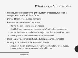
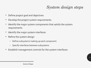
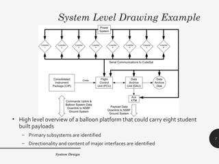
SYSTEM DESIGN
System Design
1
What is system design?
• High level design identifying the system processes, functional
components and their interfaces
• Derived from system requirements
• Provides an overview of the project
– Define the components that are needed
– Establish how components “communicate” with other components
– Determine how to modularize the project into discrete work packages
– Identify critical interfaces that must be well defined
• Used to provide initial cost, schedule & resource estimates
• Usually little or few implementation details
– As system design is refined, and lower level subsystems are included,
implementation issues may need to be addressed
System Design
2
System design steps
• Define project goal and objectives
• Develop the project system requirements
• Identify the major system components that satisfy the system
requirements
• Identify the major system interfaces
• Refine the system design
– Define subsystems making up each component
– Specify interfaces between subsystems
• Establish management controls for the system interfaces
System Design
3
System requirements
• A document listing the constraints imposed upon and the results
necessary from the project
– The project goal as well as the scientific and technical objectives should be
reflected in the system requirements
• Time spent on detailing the system requirements is worthwhile
– A greater understanding of what is required facilitates design and
implementation and improves the chances of success
• Initially focus on developing the high level scientific and technical
requirements
– Based upon current science knowledge, what is to be measured with what
resolution and accuracy?
– What constraints impose what technical limitations on your design?
System Design
4
Initial System Design
• Development of the initial system design can, at times, go hand-in-hand
with refinement of the system requirements
– Functions needed to satisfy the science requirements define the initial system
• For example, to perform any science measurement
– You will need a sensor (detector system)
– You will need to power the sensor (power system)
– You will need to read data from the sensor (data acquisition system)
– You will need to store the data (data archive system)
– You will need to control the sensor, readout, storage (control system)
– You will need to analyze the data (ground data system)
• These functions will also need to have a set of requirements specified
– For example, the power system will need to supply volts & milliamps to the sensor,
data acquisition, archive and control systems
System Design
5
Major System Interfaces
• An interface describes the linkage between two functions or processes
• Neglecting how your systems fit together can lead to disaster
– NASA Mars Climate Orbiter failed in 1999 because ground systems used “English”
units while the flight systems used “Metric” units!
• There are multiple types of interfaces
– Mechanical: How systems physically fit together
– Power: What voltage and current flows between the systems
– Electronic: The characteristics of electrical signals between systems
– Data: Format and content of information transferred between systems
– Thermal: How does heat flow between systems
– Software: How modules communicate with other modules or hardware
• The type and characteristics of all interfaces need to be identified and
defined
System Design
6
System Level Drawing Example
• High level overview of a balloon platform that could carry eight student
built payloads
– Primary subsystems are identified
– Directionality and content of major interfaces are identified
System Design
7
Refining the System Design
• After the major systems and interfaces are identified the subsystems are
described
– Each major function is composed of multiple activities, processes or modules each
with a specific function of its own
• For example, the Power System in the previous slide has the following
subsystems
– Power source that supplies the energy for the entire platform
– Separate supplies to convert the source power to the proper volts and amps
required by the FCU, DAU, DAU Disk, Aux XTM and Cubesats
• Each of the subsystems has interfaces that need specification
– How many of what kind of interface do the subsystems have?
– Is the interface to another subsystem or another system?
– What is the content of the interface?
• Traceability matrix should include these new subsystems
System Design
8
Moving to Design Specifics
• The system design refinement process continues by specifying the
subsystems of the subsystems
• For example, the FCU supply in the power system might include the
following sub- subsystems
– A relay to turn the supply on / off by computer control
– A DC / DC converter to provide the required voltage from the source
power
– An inline sensor so that volts and amps can be monitored in real-time by
the computer
• With enough iterations the system design can evolve into an actual
implementation
– Actual components to use in the design start becoming apparent
– Interfaces become very specific and well defined
System Design
9
Controlling Interfaces
• Critical interfaces need to closely monitored by use of an Interface
Control Document (ICD)
– Written description of the interface that is modified only under specific,
previously defined conditions and is used by team personnel for
implementation
• Not all interfaces need to be controlled, but an ICD can be helpful
during system design
– Written specification of the interface
– Obtain agreement between stakeholders on the interface characteristics
• Controlled ICDs should be used to help manage potential risks
– When an interface error or mismatch could result in project failure
– When stakeholders implementing the interface ends are separated in
either geographic distance or time
System Design
10
References
• Managing Requirements Website, Ludwig Consulting Services, LLC,
http://www.jiludwig.com/
• U.S. Department of Energy, Office of the Chief Information Officer, Systems
Engineering / Project Management website
http://cio.doe.gov/ITReform/sqse/project_management.htm
• U.S. Department of Energy, Office of the Chief Information Officer, Systems
Engineering Publications and Templates
http://cio.doe.gov/ITReform/sqse/publications.htm
System Design
11

Pm02 system design

  • 1.
  • 2.
    What is systemdesign? • High level design identifying the system processes, functional components and their interfaces • Derived from system requirements • Provides an overview of the project – Define the components that are needed – Establish how components “communicate” with other components – Determine how to modularize the project into discrete work packages – Identify critical interfaces that must be well defined • Used to provide initial cost, schedule & resource estimates • Usually little or few implementation details – As system design is refined, and lower level subsystems are included, implementation issues may need to be addressed System Design 2
  • 3.
    System design steps •Define project goal and objectives • Develop the project system requirements • Identify the major system components that satisfy the system requirements • Identify the major system interfaces • Refine the system design – Define subsystems making up each component – Specify interfaces between subsystems • Establish management controls for the system interfaces System Design 3
  • 4.
    System requirements • Adocument listing the constraints imposed upon and the results necessary from the project – The project goal as well as the scientific and technical objectives should be reflected in the system requirements • Time spent on detailing the system requirements is worthwhile – A greater understanding of what is required facilitates design and implementation and improves the chances of success • Initially focus on developing the high level scientific and technical requirements – Based upon current science knowledge, what is to be measured with what resolution and accuracy? – What constraints impose what technical limitations on your design? System Design 4
  • 5.
    Initial System Design •Development of the initial system design can, at times, go hand-in-hand with refinement of the system requirements – Functions needed to satisfy the science requirements define the initial system • For example, to perform any science measurement – You will need a sensor (detector system) – You will need to power the sensor (power system) – You will need to read data from the sensor (data acquisition system) – You will need to store the data (data archive system) – You will need to control the sensor, readout, storage (control system) – You will need to analyze the data (ground data system) • These functions will also need to have a set of requirements specified – For example, the power system will need to supply volts & milliamps to the sensor, data acquisition, archive and control systems System Design 5
  • 6.
    Major System Interfaces •An interface describes the linkage between two functions or processes • Neglecting how your systems fit together can lead to disaster – NASA Mars Climate Orbiter failed in 1999 because ground systems used “English” units while the flight systems used “Metric” units! • There are multiple types of interfaces – Mechanical: How systems physically fit together – Power: What voltage and current flows between the systems – Electronic: The characteristics of electrical signals between systems – Data: Format and content of information transferred between systems – Thermal: How does heat flow between systems – Software: How modules communicate with other modules or hardware • The type and characteristics of all interfaces need to be identified and defined System Design 6
  • 7.
    System Level DrawingExample • High level overview of a balloon platform that could carry eight student built payloads – Primary subsystems are identified – Directionality and content of major interfaces are identified System Design 7
  • 8.
    Refining the SystemDesign • After the major systems and interfaces are identified the subsystems are described – Each major function is composed of multiple activities, processes or modules each with a specific function of its own • For example, the Power System in the previous slide has the following subsystems – Power source that supplies the energy for the entire platform – Separate supplies to convert the source power to the proper volts and amps required by the FCU, DAU, DAU Disk, Aux XTM and Cubesats • Each of the subsystems has interfaces that need specification – How many of what kind of interface do the subsystems have? – Is the interface to another subsystem or another system? – What is the content of the interface? • Traceability matrix should include these new subsystems System Design 8
  • 9.
    Moving to DesignSpecifics • The system design refinement process continues by specifying the subsystems of the subsystems • For example, the FCU supply in the power system might include the following sub- subsystems – A relay to turn the supply on / off by computer control – A DC / DC converter to provide the required voltage from the source power – An inline sensor so that volts and amps can be monitored in real-time by the computer • With enough iterations the system design can evolve into an actual implementation – Actual components to use in the design start becoming apparent – Interfaces become very specific and well defined System Design 9
  • 10.
    Controlling Interfaces • Criticalinterfaces need to closely monitored by use of an Interface Control Document (ICD) – Written description of the interface that is modified only under specific, previously defined conditions and is used by team personnel for implementation • Not all interfaces need to be controlled, but an ICD can be helpful during system design – Written specification of the interface – Obtain agreement between stakeholders on the interface characteristics • Controlled ICDs should be used to help manage potential risks – When an interface error or mismatch could result in project failure – When stakeholders implementing the interface ends are separated in either geographic distance or time System Design 10
  • 11.
    References • Managing RequirementsWebsite, Ludwig Consulting Services, LLC, http://www.jiludwig.com/ • U.S. Department of Energy, Office of the Chief Information Officer, Systems Engineering / Project Management website http://cio.doe.gov/ITReform/sqse/project_management.htm • U.S. Department of Energy, Office of the Chief Information Officer, Systems Engineering Publications and Templates http://cio.doe.gov/ITReform/sqse/publications.htm System Design 11