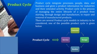
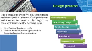
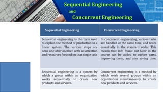
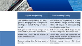
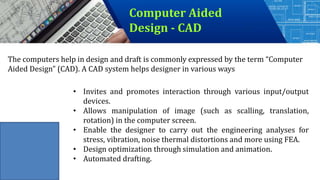
1. Product cycle- Design process- sequential and concurrent
engineering- Computer aided design – CAD system architecture-
Computer graphics – co-ordinate systems- 2D and 3D
transformations- homogeneous coordinates - Line drawing -
Clipping- viewing transformation-Brief introduction to CAD and
CAM – Manufacturing Planning, Manufacturing control-
Introduction to CAD/CAM –CAD/CAM concepts ––Types of
production - Manufacturing models and Metrics – Mathematical
models of Production Performance
Unit I – Introduction
2. Product Cycle
Product cycle integrate processes, people, data, and
business and gives a product information for industries
and their extended activity. Product cycle is the process
of managing the entire lifecycle of a product from
starting, through design and manufacture, to repair and
removal of manufactured products.
There are several Product cycle models in industry to be
considered, one of the possible product cycle is given
below
Conceive
Design
Realize
Service
Product Cycle
3. Conceive
Imagine, Specify, Plan, Innovate
The first step is the definition of the product requirements
based on company, market and customer. From this
requirement, the product's technical data can be defined. In
parallel, the early concept design work is performed defining
the product with its main functional features. Various media
are utilized for these processes, from paper and pencil to clay
mock-up to 3D Computer Aided Industrial Design.
4. Design
Describe, Define, Develop, Test, Analyze and Validate
This is where the completed design and development of the product
begins, succeeding to prototype testing, through pilot release to final
product. It can also involve improvement to existing products as well
as planned obsolescence. The main tool used for design and
development is CAD. This can be simple 2D drawing / drafting or
3Dparametric feature based solid/surface modeling. This step covers
many engineering disciplines including: electronic, electrical,
mechanical, and civil. Besides the actual making of geometry there is
the analysis of the components and assemblies.
5. Design
Describe, Define, Develop, Test, Analyze and Validate
Optimization, Validation and Simulation activities are carried out using
Computer Aided Engineering (CAE) software. These are used to
perform various tasks such as: Computational Fluid Dynamics (CFD);
Finite Element Analysis (FEA); and Mechanical Event Simulation
(MES). Computer Aided Quality (CAQ) is used for activities such as
Dimensional tolerance analysis. One more task carried out at this step
is the sourcing of bought out components with the aid of procurement
process.
6. Realize
Manufacture, Make, Build, Procure, Produce, Sell and Deliver
Once the design of the components is complete the method of manufacturing is
finalized. This includes CAD operations such as generation of CNC Machining
instructions for the product's component as well as tools to manufacture those
components, using integrated Computer Aided Manufacturing (CAM) software.
It includes Production Planning tools for carrying out plant and factory layout
and production simulation. Once details components are manufactured their
geometrical form and dimensions can be verified against the original data with
the use of Computer Aided Inspection Equipment (CAIE). Parallel to the
engineering tasks, sales and marketing work take place. This could consist of
transferring engineering data to a web based sales configuration.
7. Service
Use, Operate, Maintain, Support, Sustain, Phase-out, Retire,
Recycle and Disposal
The final step of the lifecycle includes managing of information
related to service for repair and maintenance, as well as recycling and
waste management information. This involves using tools like
Maintenance, Repair and Operations Management software.
8. Design process
It is a process in which we initiate the design
and come up with a number of design concepts
and then narrow down to the single best
concept. This involved the following steps.
• Identification of customer needs
• Problem definition, Gathering Information
• Conceptualization, Concept selection
Feasibility Study
Preliminary Design
Detailed design
Production
Consumption
Retirement
Distribution
9. Feasibility Study
The Feasibility Study using analysis of several alternatives establishes the design
concept as something which can be realized and accepted Some examples
Designs can be futile unless satisfying the original need is feasible
• At this stage, the product appears in abstract forms, but is they feasible?
• Alternative solutions must be subjected to physical and economic analyses and be
realizable from both
(i) A building must be comfortable to live in: Heating, ventilation and air
conditioning are required. Specify limits of temperature, humidity, velocity and
fresh air constituency.
(ii) National fossil fuel supplies are low: Alternative forms of energy supply are
required. Specify amount and where they are needed, and any restrictions of
space, time or pollution levels.
10. Preliminary Design
• Main purpose is selection of the best possible solution from a choice of
alternatives Make comparisons against given criteria & constraints
• Must maintain an open mind; use your judgment
11. Detailed design
• Aim is to produce a complete set of working drawings which are then
transmitted to the manufacturer
• This stage of design is far less flexible than those previous
• Design should now reflect all of the planning both for manufacture and
consumption stages Construction/testing of various components may be
required
12. Production
• Here, the device or system is actually constructed, and planning for
this should have been incorporated into the design
• Knowledge of the capability of the machines is required, since it
must be possible to build and assemble the components as
specified
• Special jigs, fixtures and even machines may be required
• Planning is vital; including quality control hold points, methods of
inspection, standards for comparison etc...
• Timing of construction may be important e.g. Climates
13. Distribution
• Transportation of the manufactured article, complete or in subassembly form must
be anticipated in the design
•
• Packaging, availability of vehicles, regulations for use of thoroughfares
,shelf/component life, warehouse storage facilities, special handling, environmental
control of temperature and humidity may need to be addressed
14. Consumption
• The product is now used by the consumer
• If the design is effect, it will have met the need
• The design may yet not be complete; redesigns and modifications may be
required depending on field trials or consumer feedback
• May need to consider maintenance of components and supply of spare
parts or subassemblies
15. Retirement
• The product will be discarded as its life cycle terminates
• It may have become obsolete whilst still serviceable and therefore the
design may not have been fully economical
• Disposal and recovery of useful materials should have been included in
the design Threats to safety should be guarded against
16. Sequential Engineering
and
Concurrent Engineering
Sequential Engineering Concurrent Engineering
Sequential engineering is the term used
to explain the method of production in a
linear system. The various steps are
done one after another, with all attention
and resources focused on that single task
In concurrent engineering, various tasks
are handled at the same time, and notes
essentially in the standard order. This
means that info found out later in the
course can be added to earlier parts,
improving them, and also saving time.
Sequential engineering is a system by
which a group within an organization
works sequentially to create new
products and services.
Concurrent engineering is a method by
which work several groups within an
organization simultaneously to create
new products and services.
17. Sequential Engineering Concurrent Engineering
The sequential engineering is a linear
product design process during which
all stages of manufacturing operate in
serial.
The concurrent engineering is a non
linear Product design process during
which all stages of manufacturing
operate at the same time.
Both process and product design run in
serial and take place in the different time.
Both process and product design run in
serial and take place in the different time
Process and Product are not matched to
attain optimal matching
Process and Product are coordinated to
Attain optimal matching of requirements
for effective quality and delivery.
Decision making done by only group of
experts.
Decision making involves full team
Involvement.
18. Sequential Engineering Concurrent Engineering
1 2 3 4
1
2
3
4
1 – Requirement 2 – Product Development
3 – Process Development 4 - Prototype
19. Computer Aided
Design - CAD
The computers help in design and draft is commonly expressed by the term “Computer
Aided Design” (CAD). A CAD system helps designer in various ways
• Invites and promotes interaction through various input/output
devices.
• Allows manipulation of image (such as scalling, translation,
rotation) in the computer screen.
• Enable the designer to carry out the engineering analyses for
stress, vibration, noise thermal distortions and more using FEA.
• Design optimization through simulation and animation.
• Automated drafting.