938 g-electrical-systems
•
4 likes•8,910 views

The document provides specifications for various off machine switch components including part numbers, functions, actuation and deactuation parameters, and contact positions. It also includes tables listing component identifiers, module identifiers, failure mode identifiers, and electrical schematic symbols and their definitions.

Recommended
More Related Content
What's hot
What's hot (20)
Viewers also liked
Viewers also liked (20)
Similar to 938 g-electrical-systems
Similar to 938 g-electrical-systems (20)
More from Silvio roman
More from Silvio roman (20)
Recently uploaded
Recently uploaded (17)
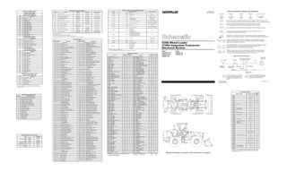
938 g-electrical-systems
- 1. Off Machine Switch Specification Part No. Function Actuate Deactuate Contact Position 3E-5464 A/C Thermostat -1.1 ± 0.8 °C (30 ± 1.4 °F) 2.2 ± 0.8 °C (36 ± 1.4 °F) Normally Open 3E-6449 Coolant Temperature (Start Aid) 38 ± 3 ºC (100 ± 5 ºF) 27 ºC MIN (81 ºF MIN) Normally Closed 3E-6450 Primary Steering Pressure Secondary Steering Pressure 1200 kPa MAX (174.0 psi MAX) 700 ± 100 kPa (102 ± 14.5 psi) A-B Normally Open A-C Normally Closed 7W-1238 Engine Oil Pressure 62 - 95 kPa (9.0 - 13.8 psi) 62 - 95 kPa (9.0 - 13.8 psi) Normally Closed 104-30074 Torque Converter Oil Temperature 129 ± 4 °C (264 ± 7 °F) 96 °C MIN (205 °F MIN) Normally Open 104-30084 Hydraulic Oil Temperature To Close: 102 ± 3 °C From Closed To Open: 90 °C MIN Normally Open³ 114-5333 A/C (High/Low) Pressure 275 - 1750 kPa¹ (39.9 - 253.8 psi) -- Normally Open² 118-51444 Coolant Temperature 107 ± 3 ºC (225 ± 5 ºF) 95 ºC MIN (203 ºF MIN) Normally Open 155-8998 Axle Oil Cooler Temperature 65 ± 3 ºC (149 ± 5 ºF) 58 ºC MIN (136 ºF MIN) Normally Open 175-3244 Brake Oil Pressure 10,700 kPa MAX (1552 psi MAX) 8960 ± 537 kPa (1300 ± 78 psi) A-B Normally Open A-C Normally Closed ¹ With Increasing pressure the closed condition can be maintained up to 2800 kPa (406 psi), with decreasing pressure the closed condition can be maintained down to 170 kPa (25 psi). ²Contact position at the contacts of the harness connector. ³ A conductive path must exist between the threads and the machine ground. 4This part has an integral temperature sender. See also Resistor, Sender and Solenoid Specifications. Component identifiers (CID¹) Module Identifier (MID²) Traction Control System Module Identifier (MID² 028) CID Component 168 Electrical System Voltage 248 Data Link 263 Sensor Supply Voltage 270 Harness Code 296 Transmission ECM 605 Left Front Speed Sensor 606 Right Front Speed Sensor 607 Left Rear Speed Sensor 608 Right Rear Speed Sensor 609 Left Front Brake Solenoid 610 Right Front Brake Solenoid 611 Left Rear Brake Solenoid 612 Right Rear Brake Solenoid 613 On/Off Solenoid 615 Articulation Sensor 616 Test/Enable Switch 653 Traction Control System ECM 687 Options Code Plug Payload Control System Module Identifier (MID² 74) CID Component 168 Electrical System Voltage 254 Payload Electronic Control Module 350 Position Sensor (Lift Linkage) 364 Pressure Sensor (Lift Cylinder Head End) 769 Pressure Sensor (Lift Cylinder Rod End) 817 Battery (Internal Backup) 820 Keypad Data Link Incorrect CST Autoshift Control Module Identifier (MID² 081) CID Component 168 Electrical System Voltage 190 Engine Speed Sensor 191 Transmission Output Speed Sensor 346 Ride Control Relay 367 Ride Control Switch 421 Load Check Solenoid 621 Downshift Switch 641 Forward High Solenoid 642 Reverse Solenoid 643 Forward Low Solenoid 644 Speed 1 Solenoid 645 Speed 2 Solenoid 646 Speed 3 Solenoid 650 Harness Code 668 Transmission Shift Lever 683 Parking Brake Alarm 687 Option Code Machine Security System Control Module Identifier (MID² 124) CID Component 168 Electrical System Voltage 248 Data Link 254 Real Time Clock 817 Battery (Internal Backup) 1391 Output Driver #1 1392 Output Driver #2 ¹ The CID is a diagnostic code that indicates which component is faulty. ² The MID is a diagnostic code that indicates which electronic control module diagnosed the fault. Failure Mode Identifiers (FMI)¹ FMI No. Failure Description 0 Data valid but above normal operational range. 1 Data valid but below normal operational range. 2 Data erratic, intermittent, or incorrect. 3 Voltage above normal or shorted high. 4 Voltage below normal or shorted low. 5 Current below normal or open circuit. 6 Current above normal or grounded circuit. 7 Mechanical system not responding properly. 8 Abnormal frequency, pulse width, or period. 9 Abnormal update. 10 Abnormal rate of change. 11 Failure mode not identifiable. 12 Bad device or component. 13 Out of calibration. 14 Parameter failures. 15 Parameter failures. 16 Parameter not available. 17 Module not responding. 18 Sensor supply fault. 19 Condition not met. 20 Parameter failures. ¹The FMI is a diagnostic code that indicates what type of failure has occurred. Electrical Schematic Symbols And Definitions Normally closed switch that will open with an increase of a specific condition. N o circle indicates that the wire cannot be disconnected from the component. This indicates that the component has a wire connected to it that is connected to ground. Wire, Cable, or Harness Assembly Wire Color Identification A AA 1 2 325-PK-14 Receptacle 200-BK-14 T This indicates that the component does not have a wire connected to ground. It is grounded by being fastened to the machine. 105-9344 T Normally open switch that will close with an increase of a specific condition (temp-press-etc.). The circle indicates that the component has screw terminals and a wire can be disconnected from it. Pin Socket Fuse Component Part Number Pin or Socket Number Wire Gauge Plug Singl e Wire Connector Circuit Number Identification Ground Connection Pressure Symbol Temperature Symbol Level Symbol Flow Symbol Circuit Breaker Symbol Reed Switch - A switch whose contacts are controlled by a magnet. A magnet closes the contacts of a normally open reed switch; it opens the contacts of a normally closed reed switch. Sender- A component that is used with a temperature or pressure gauge. The sender measures the temperature or pressure. Its resistance changes to give an indication to the gauge of the temperature or pressure. Relay (Magnetic Switch) - A relay is an electrical component that is activated by electricity. It has a coil that makes an electromagnet when current flows through it. The electromagnet can open or close the switch part of the relay. Solenoid - A solenoid is an electrical component that is activated by electricity. It has a coil that makes an electromagnet when current flows through it. The electromagnet can open or close a valve or move a piece of metal that can do work. Harness And Wire Symbols 1 1 2 2 Typical representation of a Sure-Seal connector. The plug and receptacle contain both pins and sockets. Typical representation of a Deutsch connector. The plug contains all sockets and the receptacle contains all pins. Electrical System 34 25 24 15 43 50 51 17 16 12 A A B B 18 D D C C 22 1 1 1 3 3 4 4 5 5 10 40 6 6 19 7 7 8 8 9 9 10 12 13 41 13 14 14 15 16 38 48 17 18 19 20 20 21 21 22 23 23 56 26 27 37 39 48 25 27 24 26 28 28 29 29 30 30 31 31 36 32 32 33 33 34 35 35 36 37 38 39 40 41 42 42 43 44 44 45 45 46 46 47 47 50 51 52 52 53 53 55 55 56 57 57 58 58 Machine Harness Connector And Component Locations Wire Number Wire Description Wire Color Description Wire Number Wire Color Description Power Circuits Accessory Circuits (Continued) 101 RD Battery (+) 509 WH Radio Speaker - Left (Common) 102 RD Running Lamp Breaker 511 BR Radio Speaker - Right 105 RD Key Switch 512 GN Radio Speaker - Right (Common) 108 RD 24V To 12V Converter Memory Output 513 OR A/C Compressor /Refrigerant Pressure Switch 109 RD Alt Output (+)/Main Brkr/Alt Brkr/Start Relay 515 GY Blower Motor (Hi) 110 GN Turn Signal Flasher 516 GN Blower Motor (Med) 112 PU Main Power Relay Output 517 BU Blower Motor (Low) 114 RD Warning Horn (Forward) 518 OR Hazard Flasher To Switch 115 RD Running Lamp Breaker/Spare Circuit 521 YL A/C Switch To Refrigerant Switch 116 BR Rear Floods 522 WH A/C Clutch To Thermostat Switch 117 RD Main Power Relay 537 GN Turn Signal Switch To Flasher 118 GY Wipers 538 BR Hazard Indicator 120 YL 24V To 12V Converter 539 BU Turn Signal Indicator Basic/Right 122 RD Backup Alarm/Miscellaneous Power 540 WH Turn Signal Indicator Left 123 WH Gauges/Indicator Lights 567 WH A/C Switch Jumper 124 GN HVAC 571 OR Ride Control Relay Coil 125 OR Axle Oil Cooler A514 YL CST Control To Park Brake Alarm Relay Coil 126 PK CST Autoshift Control/Shifter A538 OR Rear Window Defroster (Resistive Element) 127 OR Floods A541 PU Flasher To Indicator Lights 128 PK Kickout/Ride Control A576 GN Breaker To Compressor (Air Seat) 129 BU Cigar Lighter C529 GY Lift Head End Pressure Sensor 130 RD Stop Lamps C530 BU Lift Position Sensor 133 OR 4th Function Diverter Lighting Circuits 135 BU 24V To 12V Converter Switched Output 603 PK Rotary Beacon 136 GN Secondary Steering/Action Alarm 604 OR Stop Lamp 138 GN Payload Control System (PCS) 605 YL Turn Lamp - Left 140 BU Rear Window Defrost 606 GY Turn Lamp - Right 144 GN Heated Seat/Beacon 608 GN Flood Lamp - Rear Cab 167 OR Transmission Control System (TCS) 610 OR Head Lamp (Basic) 168 GN Quick Coupler 611 PU Head Lamp (High) 175 RD Hood Relay Control 614 PU Park/Tail/Panel Lamp 188 WH PCS Keypad 615 YL Flood Lamp - Forward Cab 189 WH Air Intake Heater (AIH) 617 BR LH Tail/Clearance Lamps 619 GN Head Lamp (Low) Ground Circuits 200 BK Main Chassis 630 GY Flood Lamp Rear (ATCH) 202 BK Transmission Control 633 BU ATCH Lighting Circuit 250 BK Payload Monitor - Customer Ground 691 GY Warning Lights To Breaker 251 BK Payload Monitor - System Ground Control Circuits 276 BK Transmission Control Ident Code 0 700 PK Hyd Lock Det Override Switch To Imp Intrlk Relay 277 BK Transmission Control Ident Code 1 702 OR Transmission Brake Switch Jumper 278 BK Transmission Control Ident Code 2 709 OR Sensor Power Supply 279 BK Transmission Control Ident Code 3 710 GN Transmission Speed Sensor A219 BK TCS Control Ground 720 PU Transmission Neutralizer Sensor A221 BK Transmission Control Options Code 0 727 GN Secondary Steering Relay Coil A222 BK Transmission Control Options Code 1 751 GN Transmission Clutch No 1 - FWD High A223 BK TCS Control Harness Code 0 752 YL Transmission Clutch No 2 - Rev A224 BK TCS Control Harness Code 1 754 BU Transmission Clutch No 3 - FWD Low A225 BK TCS Control Harness Coed 2 755 OR Transmission Clutch No 4 - Speed 1 A226 BK TCS Control Harness Code 3 761 GY Lift Positioner Switch A232 BK Transmission Control Options Code 2 762 YL Bucket Positioner Switch A250 BK Battery (-) 779 WH Quick Coupler (Engage Solenoid) A279 BK TCS Control Harness Code 4 E701 PK Ride Control Switch (Auto) A280 BK TCS Control Harness Code 5 F748 WH Ride Control Switch (On) A281 BK TCS Control Harness Code 6 F765 BR Park Brake switch A282 BK Switch/Sensor Ground F766 WH Kickout Override Switch (NO) G728 YL Kickout Override Switch (NC) Basic Machine Circuits 301 BU Shutdown Solenoid (Start Coil) G742 GN Alarm/Disarm Relay To Diode 304 WH Starter Solenoid Start Terminal G750 BU Transmission Control Forward Switch 306 GN Starter Relay Coil (+) G755 GY Transmission Control Reverse Switch 307 OR Key Switch Start Position G760 WH Transmission Control (Second Gear) 308 YL Main Power Relay Coil (+) G761 YL Transmission Control (Third Gear) 310 PU Start Aid Switch To Start Aid Solenoid G762 BR Transmission Control (Fourth Gear) 311 WH Start Aid Sol To Start Aid Cool Temp Switch G763 PU Transmission Control Neutral Switch 321 BR Backup Alarm G768 GN Transmission Control (First Gear) 322 GY Warning Horn (Forward) G787 GN Transmission Control Remote Forward Switch 326 PU Key Switch "C" Term G788 YL Transmission Control Remote Reverse Switch 331 OR Backup Alarm Relay Coil G797 BU Switch To Relay Coil 334 BU AIH Relay Coil (+) 818 BR Serial Data (Transmit) 373 GN AIH Switch To AIH Timer 819 GY Serial Data (Receive) 397 OR Hood Motor Lower E800 GN Seat Alarm To Diode Pack 398 BU Hood Motor Raise F846 PU LED Driver 1 A300 GN Hood Control Lower F853 BR Travel Speed A301 WH Hood Control Raise F880 BR Diode Block To Relay Contact G878 GY Traction Control System (TCS) Calibrate Monitoring Circuits 403 GN Alternator (R) Term 900 PU Transmission Clutch No 5 - Speed 2 404 YL Hydraulic Oil Temperature Switch 901 WH Transmission Clutch No 6 - Speed 3 405 GY Engine Oil Pressure Switch 944 OR Data Link + (CAT) 406 PU Engine Coolant Temperature Switch 945 BR Data Link - (CAT) 407 PK T/C Oil Temperature Switch 963 GN Bucket /Fork Position Detent Coil 417 GY Primary Steering Pressure Switch (NO) 964 BU Fork Position Select 419 YL Operator Monitor Parking Brake 973 BR CST Autoshift - Auto/Manual Switch 441 OR Engine Coolant Temperature Sender 975 WH CST Autoshift - Solenoid Return 442 GY Hydraulic Oil Temperature Sender 976 OR Ride Control Solenoid 443 YL T/C Oil Temperature Sender 978 GN CST Autoshift - Slow Mode Switch 1 447 PK Fuel Level Sender 987 WH Diverter Solenoid 449 BU Speedometer Sender C904 GN Relay To Relay 450 YL Engine Speed Sensor C920 GY Action Lamp - Control 453 PK Secondary Steering Pressure Switch (NO) E923 PK Front Left Wheel Proportional Solenoid 483 BR Brake Oil Pressure Switch (NC) E924 YL Front Right Wheel Proportional Solenoid 484 YL Primary Steering Pressure Switch (NC) E925 OR Rear Left Wheel Proportional Solenoid A451 PU Operator Monitor Steering Oil Temperature E926 BU Rear Right Wheel Proportional Solenoid C444 YL Alternator D+ Term E927 GN Test Mode Switch (NC) C470 BR Relay Contact To Alarm E928 WH Test Mode Switch (NO) C471 GN Relay Contact To Indicator Lamp E929 GY Articulation Angle Sensor E416 PU PCS Lift Cylinder Pressure Sensor E930 BU Front Axle Pilot Solenoid E417 OR Park Brake Switch (NC) E932 PK Front Right Wheel Speed Sensor E419 BU Relay Contact To Seat Alarm E933 YL Front Right Wheel Speed Sensor G454 PK Axle Oil Cooler Switch To Clutch Solenoid E934 OR Rear Left Wheel Speed Sensor G476 WH Traction Control Action Indicator E935 GN Rear Right Wheel Speed Sensor G486 GN Not Used E936 WH TCS Solenoid Return E955 OR Keypad Data Accessory Circuits 500 BR Wiper - Front (Park) G948 BR Implement Detent Lo Switch (NO) 501 GN Wiper - Front (Low) L906 YL Diagnostic Enable 502 OR Wiper - Front (Hi) P914 GN Used For 924G And 928G Only 503 BR Wiper - Rear (Park) P915 PK Used For 924G And 928G Only 504 YL Wiper - Rear (Low) P916 OR CST Shifter Neutral Switch Signal 505 BU Wiper - Rear (Hi) P976 BR Quick Coupler (Disengage Solenoid) 506 PU Washer - Front T901 YL MSS Exciter Coil In 507 WH Washer - Rear T902 PK MSS Exciter Coil Out 508 PU Radio Speaker - Left Related Electrical Service Manuals Form Number Title Alternator: Atch: 9W-3043 107-7977 SENR3685 SENR4757 Electric Starting Motor: Consist: Consist: 106-8558 106-8557 106-8559 SENR3859 SENR3581 Payload Control System: 112-1572 SENR6614 Traction Control System: 187-5030 SENR6719 Transmission Electronic Control System: 197-5461 SENR1218 Machine Security System Control: 160-5746 RENR2462 Resistor, Sender and Solenoid Specifications Part No. Component Description Resistance (Ohms)¹ 3E-6332 Solenoid: Start Aid 6.0 3E-8575 Solenoid: Quick Coupler 24.9 ± 0.4 8C-3663 Solenoid: Shutdown Latch Coil 1.55 ± 0.15 Unlatch Coil 10.3 ± 1.03 9G-1950 Resistor: A/C Blower Motor Heater Blower Motor Overall 2.0 ± 0.1 Tap 1.0 ± 0.05 104-3007² Sender: Torque Converter Oil Temperature 54.4 °C (130 °F): 6565 ± 695 115.6 °C (240 °F): 526 ± 61 104-3008² Sender: Hydraulic Oil Temperature 54.4 °C (130 °F): 6565 ± 695 115.6 °C (240 °F): 526 ± 61 106-5122 Solenoid: A/C Clutch 17.6 ± 0.6 118-5144² Sender: Coolant Temperature 54.4 °C (130 °F): 6565 ± 695 115.6 °C (240 °F): 526 ± 61 122-6344 Solenoid: Auxiliary Valve Float Valve Lift Positioner Valve Tilt Positioner Valve 83.7 ± 4 124-3052 Solenoid: TCS Left Front Proportional Valve TCS Right Front Proportional Valve TCS Left Rear Proportional Valve TCS Right Rear Proportional Valve 7.75 ± 1 204-3403 Sender: Fuel Level Empty: 240 to 250 Full: 28 to 33 152-8385 Solenoid: On/Off Pilot 32.6 ± 1.6 168-6452 Solenoid: Axle Oil Cooler Clutch 9.4 ± 5.0 186-1526 Solenoid: CST Forward High CST Reverse CST Forward Low CST Speed 1 CST Speed 2 CST Speed 3 31 ± 3 ¹ At room temperature unless otherwise noted. ² This part has an integral temperature switch. See also Off Machine Switch Specification. Connector Location Connector Number Schematic Location Machine Location CONN 1 D - 15 39 CONN 2 I - 15, G - 6 A CONN 3 I - 15, G - 6 A CONN 4 A - 13, A - 14 47 CONN 5 A - 13 40 CONN 6 C - 13 48 CONN 7 E - 12, I - 9 18 CONN 8 D - 12, I - 9 52 CONN 9 Aux 12V Power D - 12 53 CONN 10 C - 12 7 CONN 11 C - 12 7 CONN 12 B - 12 7 CONN 13 TCS Calibrate Plug B - 11 7 CONN 14 A/C and Heater E - 11 18 CONN 15 F - 11 2 CONN 16 F - 11 2 CONN 17 Product Link Harness H - 11 7 CONN 18 H - 11, A - 5 7 CONN 19 MSS Service Plug H - 11 7 CONN 20 G - 10 34 CONN 21 G - 10 C CONN 22 B - 10 7 CONN 23 TCS Code Plug A - 12, B - 10 7 CONN 24 B - 9 7 CONN 25 Machine Harness Code Plug A - 8, I - 7, I - 8 7 CONN 26 Options Plug A - 8, I - 7 7 CONN 27 Service Tool (ECAP) A - 8 7 CONN 28 A - 6 7 CONN 29 D - 6 A CONN 30 E- 6 A CONN 31 E - 6 A CONN 32 E - 6 A CONN 33 I - 6 59 CONN 34 A - 5, B - 3, F-3 7 CONN 35 A - 5, E - 3, G - 3 7 CONN 36 B - 5, F - 3, H - 3 7 CONN 37 D - 4 12 CONN 38 Customer Data Connection D - 3 A CONN 39 D - 3 12 CONN 40 C - 3 41 CONN 41 A - 3, E - 2, G - 3 57 CONN 42 B - 2, E - 2, G - 2 56 CONN 43 B - 2, F-3 60 CONN 44 C - 2, F -1, I - 2 55 CONN 45 D - 2, G - 2, I - 2, F - 2 55 CONN 46 D - 2, G - 2, I - 2, F - 2 55 CONN 47 H - 2 55 CONN 48 Aux Start Receptacle E - 14 58 CONN 49 Aux 12V Power Socket G - 11 51 CONN 50 G - 10 50 CONN 51 I - 11 7 The connectors shown in this chart are for harness to harness connectors. Connectors that join a harness to a component are generally located at or near the component. See the Component Location Chart. Component Schematic Location Component Location Machine Location Component Schematic Location Machine Location Alarm - Backup D - 15 3 Resistor - Heater/Air Conditioner E - 11 D Alarm - Front Secondary Steering G - 8 A Sender - Coolant Temperature D - 15 35 Alternator E - 15 4 Sender - Fuel Level E - 15 36 Alternator - ATCH E - 15 4 Sender - Hydraulic Oil Temperature C - 14 37 Assembly - Lamp D - 8 A Sender - Torque Converter Oil Temperature C - 13 38 Assembly - Lamp G - 8 A Sensor - Engine Speed C - 14 39 Battery - 12V F - 14, F - 15 5 Sensor - Left Front Wheel Speed¹ B - 2 24 Block - Terminal E - 14 7 Sensor - Left Front Wheel Speed³ D - 1 24 Breaker - Air Seat F - 10 C Sensor - Left Front Wheel Speed² G - 1 24 Breaker - Alternator B - 14 47 Sensor - PCS Lift Cylinder Head End Pressure² B - 2 21 Breaker - Auxiliary B - 14 47 Sensor - PCS Lift Cylinder Head End Pressure³ E - 1 21 Breaker - Hood B - 14 47 Sensor - PCS Lift Position² C - 2 22 Breaker - Lamp F - 10 C Sensor - PCS Lift Position³ E - 1 22 Breaker - Main B - 14 C Sensor - Right Front Wheel Speed² B - 2 26 Cigar Lighter E - 7 A Sensor - Right Front Wheel Speed³ D - 1 26 Coil - Exciter I - 11 A Sensor - Right Front Wheel Speed¹ G - 1 26 Control - Autoshift Electronic (CST) A - 7 7 Sensor - TCS Articulation Angle Position A - 4 23 Control - FNR A - 4 7 Sensor - TCS Left Rear Axle Speed I - 6 25 Control - Hood Relay A - 14 8 Sensor - TCS Right Rear Axle Speed I - 6 27 Control - MSS Electronic H - 10 7 Sensor - Transmission Speed C - 13 39 Control - Payload Electronic (PCS) E - 4 12 Service Meter G - 6 A Control - Secondary Steering Electronic B - 6 7 Shifter - CST H - 5 B Control - Traction Electronic (TCS) A - 12 9 Solenoid - (1) CST Forward High D - 13 31 Converter - 24V/12V G - 10 34 Solenoid - (2) CST Reverse D - 13 31 Defroster - Rear F - 12 17 Solenoid - (3) CST Forward Low D - 13 31 Diode Block Assembly H - 6 A Solenoid - (4) CST Speed 1 E - 13 31 Diodes - Turn Signal I - 13 A Solenoid - (5) CST Speed 2 E - 13 31 Flasher F - 6 A Solenoid - (6) CST Speed 3 E - 13 31 Flasher - Arc Suppressor I - 14 A Solenoid - 4th Function Diverter Valves H - 1 21 Flasher4 I-13 A Solenoid - A/C Clutch C - 15 6 Flasher³ I - 7 A Solenoid - Auxiliary Valve A - 8 D Fuses E - 10, F - 10 C Solenoid - Axle Oil Cooler Clutch D - 14 44 Gauge - Coolant Temperature G - 4 A Solenoid - Float Valve A - 9 D Gauge - Coolant Temperature4 I - 12 A Solenoid - Lift Positioner Valve B - 9 D Gauge - Fuel Level F - 4 A Solenoid - On/Off Pilot I - 4 30 Gauge - Fuel Level4 H - 12 A Solenoid - Quick Coupler³ F - 2 33 Gauge - Hydraulic Temperature G - 5 A Solenoid - Quick Coupler² B - 2 33 Gauge - Hydraulic Temperature4 I - 12 A Solenoid - Ride Control Valves² C - 2 21 Gauge - Speedometer F - 4 A Solenoid - Ride Control Valves³ F - 1 21 Gauge - Speedometer4 I -12 A Solenoid - Ride Control Valves¹ I - 1 21 Gauge - Torque Converter Oil Temperature F - 5 A Solenoid - Shutdown C - 15 28 Gauge - Torque Converter Oil Temperature4 H - 12 A Solenoid - Start Aid E - 13 29 Ground - Boss (Frame) A - 12 15 Solenoid - TCS Left Front Proportional I - 5 30 Ground - Cab Boss B - 12 7 Solenoid - TCS Left Rear Proportional I - 5 30 Ground - Engine Block (From Alternator) D - 15 4 Solenoid - TCS Right Front Proportional Valve I - 5 30 Ground - Engine End Frame E - 14 32 Solenoid - TCS Right Rear Proportional Valve I - 5 30 Harness - Product Link H - 11 7 Solenoid - Tilt Positioner B - 9 D Heater - Air Intake E - 13 10 Suppressor - Arc (A/C Clutch Coil) C - 15 6 Heater - Cab F- 11 18 Suppressor - Arc (Alarm Disarm Relay) G - 10 7 Indicator - Audible H - 8 A Supressor - Arc (Quick Coupler Solenoid)³ G - 2 33 Indicator - Bucket4 I - 13 A Suppressor - Arc (Quick coupler Solenoid)² B - 2 33 Indicator - High Beam4 H - 13 A Suppressor - Arc (Sec. Steering Motor Relay) A - 6 19 Indicator - LH Turn4 I - 13 A Switch - 4th Function Diverter E - 8 D Indicator - RH Turn4 H - 13 A Switch - A/C Compressor F - 8 D Indicator - Right Turn F - 6 A Switch - A/C Refrigerant (Pressure) C - 15 6 Indicator - Hazard F - 6 A Switch - Air Inlet Heater F - 7 A Indicator - High Beam F - 6 A Switch - Axle Oil Cooler Temperature A - 14 47 Indicator - Left Turn G - 6 A Switch - Beacon F - 7 A Keypad - PCS D - 4 12 Switch - Blower F - 9 D Lamp - Action B - 8 7 Switch - Brake Oil Pressure D - 3 43 Lamp - COSA License Plate D - 15 3 Switch - Brake Oil Pressure F - 2 43 LED - BI Color I - 11 A Switch - Brake Oil Pressure I - 3 43 Module - TCS Display D - 4 13 Switch - Bucket Fork Select E - 8 D Motor - Front Washer E - 3 15 Switch - Bucket Positioner C - 2 D Motor - Front Washer³ F - 2 15 Switch - Bucket Positioner E - 1 D Motor - Front Washer¹ I - 2 15 Switch - Bucket Positioner H - 1 D Motor - Front Wiper E - 4 16 Switch - Defrost F - 8 D Motor - Heater/Air Conditioner Blower E - 11 18 Switch - Dimmer F - 6 B Motor - Hood Actuator A - 14 1 Switch - Disconnect F - 14 32 Motor - Rear Washer E - 3 15 Switch - Downshift B - 9 D Motor - Rear Washer³ F - 2 15 Switch - Engine Oil Pressure C - 14 40 Motor - Rear Washer¹ I - 3 15 Switch - Fork Positioner H - 1 D Motor - Rear Wiper F - 12 17 Switch - Forward Horn F - 6 B Motor - Secondary Steering A - 6 19 Switch - Front Intermittent Wiper D - 7 A Motor - Starter E - 14 14 Switch - Hazard G - 7 A Panel - FNR LED4 H - 13 A Switch - Hood Actuator A - 14 8 Panel - FNR LED G - 4 A Switch - Hydraulic Lock Detent Override F - 8 A Plug - 938G Machine Harness Code I - 8 7 Switch - Key Start F - 6 B Plug - 938G TCS Code B - 10 7 Switch - Kickout On/Off E - 8 D Plug - IT38G Machine Code I - 7 7 Switch - Lamp H - 6 A Plug - IT38G TCS Code B - 10 7 Switch - Lift Positioner² C - 2 33 Plug - Machine Harness Code A - 8 7 Switch - Lift Positioner³ E - 1 33 Plug - MSS Service I -11 7 Switch - Lift Positioner¹ H - 1 33 Plug - Options A - 8 7 Switch - Parking Brake G- 11 45 Plug - Ride Control I - 7 7 Switch - Primary Steering Oil Pressure A - 6 42 Plug - TCS Assembly Test A - 12 7 Switch - Quick Coupler F - 8 D Plug - TCS Brake Bleed A - 12 7 Switch - Rear Wiper C - 7 A Plug - Calibrate B - 11 7 Switch - Remote FNR B - 8 D Radio G - 11,G-13 A Switch - Ride Control E - 8 D Relay - Air Inlet Heater (AIH) E - 13 20 Switch - Secondary Steering Manual D - 7 A Relay - Alarm Disarm D - 11 C Switch - Secondary Steering Pressure A - 6 42 Relay - Alarm Disarm E - 11 C Switch - Service Brake D - 3 41 Relay - Backup Alarm D - 10 C Switch - Start Aid D - 8 A Relay - FNR D - 10 C Switch - Start Aid Coolant (Temperature) D - 15 44 Relay - Implement Interlock D - 10 C Switch - TCS Test/Enable E - 8 A Relay - Main Power F - 10 C Switch - Thermostat E - 11 18 Relay - Park Brake Alarm D - 10 C Switch - Transmission Auto/Manual D - 8 D Relay - Rear Flood B - 13 C Switch - Transmission Neutral C - 3 46 Relay - Ride Control D - 10 C Switch - Transmission Neutralizer F - 7 46 Relay - Seat Alarm D - 10 C Switch - Turn Signal F - 5 A Relay - Secondary Steering Motor A - 6 C Switch - Turn Signal4 H - 15 A Relay - Start B - 14 C Timer - Air Inlet Heater (AIH) G - 8 A Machine locations are repeated for components located close together. C = Located on or near relay/fuse panel. ¹IT38G ³JAPAN A = Located on or near dash panel. D = Located on or near right console. ²938G 4COSA B = Located on or near steering column. ©2001 Caterpillar All Rights Reserved Printed in U.S.A. RENR4326-01 November 2001 938G Wheel Loader IT38G Integrated Toolcarrier 938G: 4YS1878-UP 6WS2579-UP 9HS801-UP IT38G: 7BS900-UP 1CW391-UP
- 2. TURN SIGNAL DIODES LH TURN IND 115-1748 BUCKET IND 115-1748 FORWARD GND NEUTRAL FNR LED PANEL GN BK PK HIGH BEAM IND 115-1748 RH TURN IND K RIGHT SPEAKER FLASHER 606-GY 538-BR-18 605-YL J J J LEFT J J 540-WH-18 200-BK-18 633-BU-18 200-BK-18 P914-GN-18 200-BK-18 P915-PK-18 752-YL-18 611-PU-18 200-BK-18 539-BU-18 SPEAKER 509-WH 508-PU 509-WH 511-BR 511-BR 509-WH WIRES THAT HAVE SYSTEM VOLTAGE WHEN THE KEY SWITCH IS OFF. WIRES THAT HAVE SYSTEM VOLTAGE WHEN THE KEY SWITCH IS ON. 123-WH-18 447-PK-18 ATCH BEACON OPTIONAL BEACON SOCKETS STARTING CIRCUIT. GAUGE CIRCUIT. MONITOR CIRCUIT. PANEL LAMP CIRCUIT. TURN SIGNAL AND WASHER/WIPER CIRCUIT. HEATER AND AIR CONDITIONER CIRCUIT. GROUND CIRCUIT. TRANS. CONTROL (TCS, CST). BACK LIGHT 5 614-PU-18 944-OR-18 24V/12V CONVERTER BK BACK LIGHT 6 3 6 ARC 3 1 9 7 5 11 13 18 19 24 26 29 31 40 42 45 47 52 53 58 60 62 66 + BAT GND +V CRANK DRIVER OUT TIRIS INTERFACE SIGNAL LINE +V ON POSITION DRIVER IN +V ON SWITCH DRIVER OUT CAN DATA LINK + +V CRANK POSITION DRIVER IN GND KEYSWITCH IN ALTERNATOR R TERMINAL IN SWITCH INPUT 1 +V CRANK POSITION IN CAN DATA LINK - CAT DATA LINK + CAT DATA LINK - CAT DATA LINK GND +V CRANK DRIVER GND RETURN TIRIS GND RETURN LED SOURCE DRIVER OUT SEGMENT 1 LED SOURCE DRIVER OUT SEGMENT 2 NEUTRAL START ENABLE INPUT SWITCH IN 2 TIRIS ANTENNA TAP 2 SUPPRESSOR 120-YL 133-OR 140-BU MSS_ECM 128-PK 128-PK-18 PLUG INTO HARNESS AS. C AT LOC F-6 1 A346-BU-18 114-RD-18 114-RD-18 126-PK-18 202-BK-18 202-BK-18 202-BK-18 403-GN-18 403-GN-18 944-OR-18 944-OR-18 945-BR-18 945-BR-18 F846-PU-18 G948-BR-18 L906-YL-18 T901-YL-18 BK-18 1 308-YL 2 3 4 326-PU-18 307-OR-18 A346-BU-18 PLUG INTO KEY SW EXCITER_COIL RD GN RED BI_COLOR_LED MSS_SERVICE_PLUG TO MAIN CAB HARN LOC A-5 A576-GN-14 CONN 19 CONN 18 C GN-14 2 UU JUMPER PLUG FOR 24V RADIO 2 1 3 3 1 2 4 200-BK-18 126-PK-18 449-BU-18 516-GN 108-RD-18 200-BK TU GN-18 G RD/YL-18 GN/RD-18 GROUND GROUND L59 L61 L72 L71 BAT BAT SEND L73 L73 D A 2 1 T902-PK-18 F846-PU-18 G948-BR-18 L906-YL-18 114-RD-18 126-PK-18 202-BK-18 403-GN-18 944-OR-18 945-BR-18 114-RD-18 126-PK-18 202-BK-18 403-GN-18 944-OR-18 HYDRAULIC TEMP 155-5233 BACKLIGHT 115-1748 COOLANT TEMP 155-5232 BACKLIGHT 115-1748 SPEEDOMETER 196-4217 BACKLIGHT 115-1748 FUEL LEVEL BACKLIGHT TORQUE CONV TEMP 617-BR 614-PU-18 CONTROL SYSTEM CIRCUIT. START AID CIRCUIT. MSS CONTROL. C A +V TURN WARNING LAMPS +V HAZARD GROUND BUCKET IND. GROUND ILLUMINATION + RIGHT SPKR + SPKR - BATTERY ALL DASHED LINES ARE ATTACHMENTS. LEFT TURN LAMP 3E-6466 RIGHT TURN RIDE CONTROL SOLENOID VALVES 149-2658 4TH FUNCTION DIVERTER SOLENOID VALVES FORK POSITIONER SWITCH RD-18 BK-18 V RD-18 1 GN-18 OR-18 + BATTERY BK-18 OR-18 BK-18 OR-18 FLOOD LAMP LAMP FLOOD LAMP GN-18 SOLENOID GROUND + BATTERY BUCKET POSITIONER SWITCH LIFT POSITIONER SWITCH LEFT FRONT WHEEL SPEED SENSOR 109-7330 RIGHT FRONT WHEEL SPEED SENSOR LH HI/LO/POSITION/TURN LAMP 605-YL 200-BK-14 619-GN-14 FORWARD HORN 976-OR-18 L 987-WH-18 200-BK-18 987-WH-18 200-BK-18 200-BK-18 200-BK-18 F766-WH-18 OR CCC SIGNAL -18 -18 -18 -18 1 B BUCKET POSITION/ TURN 619-GN-14 5 4 BU-18 RD-18 WH-18 YL-18 V RH HI/LO/POSITION TURN LAMP CCC E932-PK-18 E933-YL-18 709-OR-18 A219-BK 619-GN-14 AAA 4 605-YL 200-BK-14 606-GY 617-BR 200-BK-14 614-PU-14 114-RD-18 709-OR-18 E932-PK-18 A219-BK 709-OR-18 L 200-BK-14 200-BK-14 606-GY-14 606-GY-14 605-YL-14 605-YL-14 200-BK-14 976-OR-18 L 976-OR-18 BRAKE OIL PRESSURE SW 200-BK-14 617-BR 606-GY 614-PU-14 619-GN-14 REAR 506-PU-18 WASHER 611-PU-14 617-BR-14 619-GN-14 200-BK-14 611-PU-14 FRONT WASHER FRONT WASHER 4 BRAKE OIL 2 GN-18 619-GN-14 611-PU-14 200-BK-14 U 1 FORWARD A A B L RD-18 BK-18 HI/LO BEAM HEAD LAMP OR-18 + BATTERY SOLENOID BK-18 GROUND SOLENOID +V GROUND F766-WH-18 762-YL-18 200-BK-18 200-BK-18 P P 138-GN-18 251-BK-18 B A C C529-GY-18 LH TURN & CLEARANCE LAMP RIDE CONTROL SOLENOID VALVES HEAD LAMP RIGHT TURN & WIDTH LAMP PCS LIFT BUCKET POSITIONER SWITCH LIFT POSITIONER SWITCH POSITION SENSOR OR B -18 +V BK -18 A GROUND PCS LIFT CYL HEAD END PRESS SENSOR LEFT FRONT WHEEL SPEED SENSOR RIGHT FRONT WHEEL SPEED SENSOR -18 -18 -18 -18 SIGNAL SYMBOL DESCRIPTION CIRCUIT CONNECTED CIRCUIT NOT CONNECTED ELECTRICAL CONNECTION TO MACHINE STRUCTURE INTERNAL ELECTRICAL CONNECTION TO SURFACE OF COMPONENT CONNECTOR CIRCUIT GROUPING H# DESIGNATION ATCH WIRE, CABLE, COMPONENT CIRCUIT CONNECTED BLADE, SPADE, RING OR SCREW TERMINAL SPLICE 114-RD-18 A346-BU-18 307-OR-18 126-PK-18 307-OR-18 307-OR-18 3 6 AUX 12V BK YL E417-OR-18 POWER SOCKET E800-GN-18 E419-BU-18 200-BK-18 C 522-WH HEATER GP 107-3317 RESISTOR BLOWER THERMOSTAT SW E417-OR-18 522-WH 515-GY 200-BK-18 276-BK-18 1 276-BK-18 277-BK-18 3 4 5 BK-18 334-BU-18 HYD LOCK DETENT OVERRIDE 779-WH-18 QUICK COUPLER SW 1 123-WH-18 10 6 5 7 3 4 8 9 11 E800-GN-18 484-YL-18 LAMP COLOR FUNCTION RED RED RED RED RED 537-GN 518-OR 538-BR H H 6 3 L1 L2 L3 L4 L5 ENGINE OIL PRESS BRAKE PRESS NOT USED HYD OIL TEMP COOLANT TEMP AUDIBLE 4 8 7 987-WH 4TH FUNCTION DIVERTER SW E928-WH-18 E927-GN-18 TCS TEST/ ENABLE SW START NOT USED NOT USED NOT USED ALTERNATOR PARK BRAKE 202-BK-18 Y 1 2 441-OR-18 442-GY-18 447-PK-18 123-WH 611-PU-18 614-PU-18 449-BU-18 1 78 3 2 4 MATING CONNECTORS LOC G-6 9 8 7 6 5 4 3 2 1 10 11 TURN SIGNAL SW 4 1 2 3 6 5 200-BK-18 779-WH-18 200-BK-18 ARC SUPPRESSOR 106-8704 P976-BR-18 200-BK-18 MUR440 1 ARC SUPPRESSOR P976-BR-18 GN-18 BK-18 BK-18 GN-18 779-WH-18 MUR440 106-8704 200-BK-18 REAR WASHER A219-BK-18 709-OR-18 779-WH-18 P976-BR-18 1 4 3 S-2 S-1 R R R QUICK COUPLER SOL. 3E-8575 483-BR-18 619-GN-14 976-OR-18 614-PU-14 617-BR 507-WH-18 762-YL-18 761-GY-18 F766-WH-18 200-BK-18 C L 10 11 L R C B A 779-WH-18 2 1 2 200-BK-18 2 1 2 779-WH-18 200-BK-18 NOTE H P976-BR-18 200-BK-18 P976-BR-18 FLOOD UUU UUU 160-7893 160-7893 ACC + NC NC CIRCUIT BOX RADIO (JAPAN) 161-1284 509-WH 200-BK-18 633-BU-18 B G I J E 49 49A 30B 31 633-BU-18 752-YL-18 540-WH-18 P914-GN-18 539-BU-18 P915-PK-18 611-PU-18 605-YL 538-BR-18 606-GY 200-BK-18 200-BK-18 200-BK-18 200-BK-18 200-BK-18 200-BK-18 200-BK-18 200-BK-18 200-BK-18 200-BK-18 123-WH-18 123-WH-18 123-WH-18 123-WH-18 123-WH-18 441-OR-18 442-GY-18 443-YL-18 447-PK-18 449-BU-18 614-PU-18 614-PU-18 614-PU-18 614-PU-18 H NC 1 110-GN-18 189-3158 200-BK-18 200-BK-18 200-BK-18 200-BK 135-BU 135-BU 200-BK K B K BATTERY BACKUP 160-7892 135-BU K BACKUP + LEFT SPKR + ANTENNA F C A D RADIO 135-BU 511-BR 508-PU 509-WH 160-7891(JAPAN) 135-BU NOTE B DISCONNECT SWITCH TERMINAL BLOCK 8C-6358 TTT NOTE: TERMINAL BLOCK IS REQUIRED WITH ATCH JUMP 200-BK 441-OR-18 LEFT SIDE ENGINE BK-00 TO ENGINE COSA LICENSE PLATE LAMP STARTER TO ENGINE WW WW WW WW 537-GN-18 752-YL-18 540-WH-18 P914-GN-18 539-BU-18 P915-PK-18 611-PU-18 605-YL 605-YL 538-BR-18 606-GY 200-BK-14 123-WH 441-OR-18 442-GY-18 443-YL-18 447-PK-18 449-BU-18 WW 403-GN-18 614-PU-14 200-BK-14 614-PU-14 12V BATTERY 115-2422 AUX START 1 614-PU-14 2 200-BK-14 200-BK-14 JAPAN (ATCH) MAIN POWER RELAY 159-9108 ZZZ ZZZ ZZZ 1 308-YL-18 200-BK-18 2 GROUND OPERATOR 4 1 515-GY-14 200-BK-18 200-BK-18 E419-BU-18 F765-BR-18 202-BK-18 SPEED AIR SEAT BREAKER LAMP BREAKER 112-PU-10 112-PU-10 10A = 113-8490 10A C 10A 10A ALARM DISARM RELAY ALARM DISARM RELAY 200-BK-18 200-BK-18 REAR WIPER 615-YL-14 L72 L71 L71 C444-YL-18 321-BR-18 614-PU 605-YL 310-PU 406-PU-18 202-BK-18 200-BK 135-BU 511-BR-18 200-BK-14 A538-OR 118-GY 503-BR 504-YL 615-YL-14 603-PK 614-PU 115-RD-10 117-RD-4 C444-YL-18 310-PU 443-YL-18 407-PK-18 334-BU-18 404-YL-18 405-GY-18 406-PU-18 608-GN 326-PU-18 306-GN-18 441-OR-18 447-PK-18 605-YL 606-GY 755-OR-18 202-BK-18 202-BK-18 938G MACHINE CODE HARNESS CODE PLUGS 453-PK-18 BU OR BU PK WH YL 278-BK-18 LAMP AS C F748-WH-18 F765-BR-18 XMSN NEUTRALIZER SW OR RD GN WH PK BK OUT OUT G768-GN-18 G760-WH-18 G761-YL-18 G762-BR-18 306-GN-18 G763-PU-18 G755-GY-18 G750-BU-18 126-PK-18 202-BK-18 YL 538-BR L101 L52 L52 L101 L51 L51 202-BK-18 202-BK-18 HORN 6 975-WH-18 1 2 6 A B L 138-GN-18 C530-BU-18 138-GN-18 251-BK-18 E932-PK-18 709-OR-18 E933-YL-18 ABBREV COLOR RD WH OR YL PK HARNESS AS. A D 217-0206 02 I-11 MACHINE SECURITY SYS 01 B-2 P 129-8111 01 E-1 PCS (JAPAN) STD MSS KEY SW 01 D-4 TCS DISPLAY ATCH 112-2960 01 AAA RIDE CONT-938G/IT38G 00 D-4 ATCH 03 217-0205 135-1922 ZZZ 160-5599 00 G-9 MAIN POWER RELAY(JAPAN) ATCH 8Y-9603 138-0715 G-10 F-14 F-15 F-14 F-14 TT UU VV KK 8R-6359 LL 00 02 01 01 01 THIS SCHEMATIC IS FOR THE 938G/IT38G COMPONENTS ARE SHOWN INSTALLED ON A FULLY OPERABLE MACHINE WITH THE KEY AND ENGINE OFF, THE DATA LINK WIRES (944-OR & 945-BR) MUST BE CIRCUIT WIRES (T901-YL & T902-PK) MUST BE TWISTED TOGETHER AT LEAST 1 TURN PER MM 200-BK-18 L61 L61 L60 L60 C904-GN-18 G797-BU-18 P915-PK-18 F766-WH-18 307-OR-18 C471-GN-18 122-RD-18 E419-BU-18 E417-OR-18 E800-GN-18 200-BK-18 200-BK-18 200-BK-18 200-BK-18 G CAB GROUND BOSS 135-BU 108-RD-18 200-BK A451-PU-18 200-BK A A NOTE: TO 614-PU GN/RD-18 CONN TO LIGHTING GP-JAPANESE ROADING ATCH RD-00 AIR INTAKE HEATER 108-5747 STRAP TO ENGINE SOL 6 GN 975-WH-18 OR-2 COAXIAL CABLE AS. 109-8981 L3 L3 L3 L3 REAR WASHER BRAKE OIL PRESSURE SW 944-OR-18 945-BR-18 CONN 38 NC NC C CONN 40 XMSN NEUTRAL SW PRESSURE SW BU 12 11 6 1 2 10 9 8 7 4 5 3 5 3 7 1 10 11 8 2 6 9 606-GY 762-YL-18 322-GY-18 C F-6 H-15 F-6/H-7/I-12 B-2 NOTE R 619-GN-14 B-1 483-BR-18 507-WH-18 506-PU-18 200-BK-14 322-GY-18 976-OR-18 975-WH-18 762-YL-18 F766-WH-18 C530-BU-18 3 2 5 138-GN-18 B-9/A-5 CST SOLENOID T T/C OIL TEMP SW/SENDER SOL 5 SOL 4 GN SOL 3 GN 975-WH-18 2 GN SOL 2 GN GN SOL 1 WH-18 710-GN-18 TRANSMISSION SPEED SENSOR 442-GY-18 25 5 3 L81 L81 CONN 4 CONN 5 200-BK 202-BK-18 202-BK-18 202-BK-18 202-BK-18 202-BK-18 OPTIONS CODE PLUGS 614-PU-14 202-BK-18 A232-BK-18 FLASHER JAPAN OPTION 4 3 2 L28 L28 L27 L30 L29 L29 C471-GN-18 2 5 144-GN BACKLIGHT 3 115-1748 614-PU-18 IT38G MACHINE FRONT INTERMITTENT 2 1 3 L28 L27 506-PU-18 500-BR 8 7 4 3 1 118-GY 2 3 4 WIPER SW -18 -14 -14 -14 -18 -18 RD YL BU 761-GY-18 202-BK-18 H 1 3 4 5 7 6 2 CIGAR LIGHTER 202-BK-18 123-WH-18 HAZARD SW AIR INTAKE 200-BK-18 SECONDARY STEERING MANUAL SW 126-PK-18 126-PK-18 ATCH TRACTION CONTROL SYSTEM (TCS) RIGHT FRONT PROP SOL LEFT REAR PROP SOL RIGHT REAR PROP SOL 24V OUTPUT HYDRAULIC TEMP 447-PK-18 TORQUE CONV ATCH TRACTION CONTROL SYSTEM (TCS) FNR LED PANEL 148-0643 518-OR L16 L16 G787-GN-18 G788-YL-18 L14 DIODE_BLOCK 144-3902 10 11 IN IN P914-GN-18 P915-PK-18 1 L15 L15 L14 L14 L14 L13 L13 L17 L17 L17 L17 L17 L13 L14 L15 751-GN-18 L35 L36 L37 G760-WH-18 L31 L31 403-GN-18 251-BK-18 605-YL 606-GY 617-BR 507-WH-18 C530-BU-18 976-OR-18 762-YL-18 202-BK-18 126-PK-18 DOME LAMP BULB 140-BU 614-PU-18 614-PU-18 614-PU-18 976-OR-18 700-PK 2 RD-16 BACKLIGHT 200-BK-18 200-BK 508-PU-18 511-BR-18 441-OR-18 449-BU-18 E930-BU-18 200-BK-18 LEFT FRONT PROP SOL SEND 200-BK-18 114-RD-18 200-BK-14 C530-BU-18 138-GN-18 E932-PK-18 LEFT TURN LAMP RIGHT TURN LAMP FLOOD LAMP RIDE CONTROL SOL VALVES RD-18 BK-18 FLOOD LAMP 1 BUCKET POSITIONER SW LIFT POSITIONER SW BK-18 OR-18 GROUND + BATTERY PCS LIFT POSITION SENSOR A219-BK-18 709-OR-18 E933-YL-18 3 4 E932-PK-18 200-BK-14 V 1 FORWARD HORN 976-OR-18 +V PCS LIFT CYL HEAD END PRESSURE SENSOR 779-WH-18 200-BK-18 ARC SUPPRESSOR P976-BR-18 200-BK-18 ATCH ATCH ATCH STD NOTE W 200-6351 NOTE D J J 134-9569 J J J J J J 200-BK-18 J COSA GAUGE ATCH J J J J J J J J J J J J J J J J J 172-9200 4 3 2 1 MACHINE SECURITY SYSTEM (ATCH) D D G742-GN-18 BOTTOM 129-BU 120-YL 189-WH-18 144-GN 130-RD 122-RD 5 419-YL-18 1 2 1 2 5 4 MID H G760-WH-18 F880-BR-18 P914-GN-18 751-GN-18 754-BU-18 -18 -18 L13 P914-GN-18 G787-GN-18 G788-YL-18 P916-OR-18 G768-GN-18 G760-WH-18 G761-YL-18 G762-BR-18 321-BR-18 1 441-OR-18 442-GY-18 447-PK-18 611-PU 449-BU-18 200-BK-14 606-GY TURN SIGNAL SWITCH DIMMER SW 111-7897 537-GN L7 L11 L10 L8 518-OR J 00 I-15 GAUGE (COSA) 201-0789 443-YL-18 200-BK-14 605-YL-18 606-GY-18 P914-GN-18 P915-PK-18 752-YL-18 518-OR-18 537-GN-18 538-BR-18 110-GN-18 606-GY 605-YL 539-BU-18 540-WH-18 A541-PU-18 537-GN-18 12 56 614-PU-18 200-BK-18 200-BK-18 200-BK-14 606-GY A451-PU-18 518-OR-18 ARC SUPPR FLASHER 6C-8846 537-GN-18 537-GN-18 691-GY-18 2 C C 2 TURN IND. 614-PU-18 200-BK-18 115-1748 148-0643 4 3 2 1 YL REVERSE SERVICE E933-YL-18 NOTE F: 108-1029 MAIN POWER RELAY CIGAR LIGHTER AIR INLET HEATER 106-8558 1 BACKLIGHT LIFT POSITN SENSOR TX A CHANNEL 251-BK-18 12 GROUND 250-BK-18 UNUSED GROUND BACK Z 200-BK-18 200-BK-18 614-PU-18 307-OR-18 G787-GN-18 LIFT 123-WH-18 POSITIONER SOLENOID A/C 521-YL COMPRESSOR SW 567-WH 107-6034 BUCKET/FORK SELECT SW KICKOUT 107-6031 E701-PK-18 RIDE CONTROL SW XMSN AUTO/ MANUAL SW 614-PU 138-GN-18 167-OR 114-RD-18 TILT A538-OR 614-PU-18 614-PU-18 REMOTE FNR SW 3 1 3 POSITIONER SOLENOID 118-GY 503-BR 505-BU 108-RD-18 12 117-2311 200-BK-18 200-BK-18 115-1748 155-5784 11 CODE 518-OR 200-BK-18 614-PU-18 UNUSED WASH PARK LOW HIGH GROUND WASHER B+ B H REAR WIPER SW XMSN 135-BU BK-18 C PCS STOP LAMPS KEY SWITCH 9W-0335 PRIM STEER A232-BK-18 105-RD 144-GN 709-OR-18 A219-BK CST SHIFTER EXT FWD EXT REV EXT NEUT FIRST GEAR START RELAY NEUTRAL FORWARD 122-RD-18 TRANS ECM & SHIFTER F 200-BK-14 FLOOD 109-7041 ANTENNA C444-YL-18 403-GN-18 521-YL 321-BR-18 BK GY BR REAR DEFROSTER 2 7 10 L70 CONN 9 AUX 12V POWER 407-PK-18 407-PK-18 AIH RELAY START AID SOLENOID 407-PK-18 FLASHER 537-GN 538-BR 503-BR 200-BK 504-YL 505-BU 615-YL-14 484-YL-18 RD 32 6 + 5 4 - 1 L5 L3 L4 A219-BK-18 L1 L6 L2 LAMP AS 148-0641 GY 709-OR-18 E934-OR-18 E936-WH ON/OFF PILOT SOL FORWARD NEUTRAL LEFT SPEAKER -18 -18 614-PU-18 200-BK-18 PU 189-WH-18 GN BK 118-GY WIPERS 123-WH GAUGES/IND LIGHTS 128-PK 138-GN-18 10A BEACON/HEATED SEAT 12V BATTERY 115-2422 BA RADIO PARKING BRAKE SW F765-BR-18 NOTE T 136-GN RECEPTACLE 126-PK-18 SHIFTER POS 24/12 CONVERTER TCS LEFT REAR AXLE SPEED SENSOR OR WH -18 -18 200-BK-18 +V SIGNAL TCS RIGHT REAR AXLE SPEED SENSOR 200-BK-18 614-PU-18 SERVICE 161-3932 KEY START SW 518-OR 127-OR-14 608-GN-14 122-RD 102-RD-14 615-YL-14 537-GN 129-BU 484-YL-18 15A J 10A 116-BR 161-8906 608-GN-14 617-BR L21 C471-GN-18 727-GN-18 484-YL-18 417-GY-18 F 727-GN-18 C H 610-OR-14 135-BU 200-BK 310-PU ROOF 109-7041 122-RD 200-BK CC EE 200-BK-18 TCS TEST/ENABLE SW OPERATION 200-BK-14 160-7893(JAPAN) 515-GY-14 167-OR TCS BU ALARM/MISC PWR 10A ACTION LAMP OPTIONS CONN 26 C A C 10A BAT GRD BACKLIGHT 115-1748 COOLANT TEMP BACKLIGHT 115-1748 SPEEDOMETER 196-4217 E419-BU-18 SEAT ALARM RELAY RIDE CONTROL RELAY 130-3033 122-RD 144-GN-18 E417-OR-18 SEAT ALARM HEATER 2 B+ ENGINE COOLANT SW/SENDER T LICENSE CONN FOR ALTERNATOR 107-7977 ATCH LICENSE PLATE SHUTDOWN SOLENOID LH FLOOD LAMP S RD-18 T G A BA A A A LH STOP/TAIL/PARK LAMP RD-18 BK-18 LEFT TURN LAMP FUEL LEVEL 1 A/C REFRIGERANT SW NOTE A 1 10A 615-YL 200-BK-14 GRD 134-4093 144-GN-18 ENGINE SPEED 30A FRONT WIPER 4 H 2 63 C 15A 5 GN OR 115-RD-10 200-BK-14 SENSOR BREAKER/RELAY PANEL K 12 443-YL-18 406-PU-18 751-GN-18 L40 L39 C C RELAY 200-BK-18 417-GY-18 484-YL-18 453-PK-18 BOSCH MOTOR 453-PK-18 -18 -18 -18 -18 -18 -18 -18 -18 A B ARC SEC STR RLY PRIM FAULT + BATTERY KEY SWITCH UNUSED (GND) PRIM PRES SW UNUSED SUPPRESSOR RD-00 KKK SECONDARY STEERING CONTROL ATCH SECONDARY STEERING 118-GY 116-BR 123-WH 126-PK 138-GN-18 130-RD 114-RD-18 PARK BRAKE ALARM RELAY 321-BR-18 BACKUP ALARM L49 C904-GN-18 FNR C904-GN-18 G797-BU-18 IMPLEMENT INTERLOCK 5 L47 L47 GGG 727-GN-18 10A BU-16 ARC SUPPRESSOR GN-18 BK-18 BK-18 1 QUICK COUPLER SOL. 200-BK-14 200-BK-18 200-BK-18 F766-WH-18 -18 -18 +10V A AAA 709-OR-18 E932-PK-18 A219-BK 709-OR-18 A219-BK LEFT FRONT WHEEL SPEED SENSOR RIGHT FRONT WHEEL SPEED SENSOR -18 -18 -18 -18 FOR IT38G ONLY. ON STD MACHINE, CONNECT TERMINALS 2 & 3 WITH JUMPER WIRE AS. 9V-7204 FLUORESCENT SERVICE LAMP IS AVAILABLE AND CAN BE POWERED FROM 110-0553 WIRE AS. USED ON MACHINES NOT EQUIPPED WITH TUV SPEED LIMITER J 727-GN-18 202-BK-18 702-OR-18 F START RELAY 80A 308-YL AIH TIMER C 3 727-GN-18 1 8 7 614-PU-18 200-BK-18 C C 2G-5298 140-BU 10A G 10A RD-00 15A = 113-8491 80A 110-7887 502-OR 123-WH-18 C 123-WH-18 442-GY-18 447-PK-18 H BAT SEND NEG BAT GRD GRD 101-RD-4 10A LEFT STOP/TAIL/ PARK/TURN/ BACKUP LAMP PLATE LAMP 5A-3808 RIGHT STOP/TAIL/ PARK/TURN/ BACKUP LAMP 447-PK-18 200-BK-18 614-PU-18 FUSES SIG 102-RD-14 2 L1 AMBER 608-GN L4 L5 D TCS DATA LINK PCSII DATA LINK 944-OR-18 944-OR-18 945-BR-18 L84 122-RD C 202-BK-18 LOC J NOTE E C-15 W 109-RD-4 118-GY 10A H 603-PK E L84 102-RD-14 127-OR-14 10A 614-PU-18 J J 10A 617-BR 10A J REVERSE + BATTERY GROUND UNUSED UNUSED L18 L18 L18 NOTE U 167-0138 10A J A J 200-BK-14 608-GN Z 123-WH-18 614-PU-18 102-RD-14 118-GY C470-BR-18 144-GN 118-GY C471-GN-18 123-WH-18 L75 HYDRAULIC 101-RD-12 20A H 118-GY 419-YL-18 200-BK-18 AB 8 310-PU 7 BLOWER SW 200-BK-18 975-WH-18 200-BK-18 200-BK-18 614-PU-18 L48 L48 DOWNSHIFT SW 158-8863 NOTE W 134-4092 NC 944-OR-18 EE 149-2658 FF 331-OR-18 H 614-PU-18 200-BK-18 308-YL 310-PU 6 BK-00 G S MTR BAT MOTOR XMSN SHIFTER IN NEUTRAL AND WITH PARK BRAKE SET 5 505-BU E ENGINE (JAPAN) ATCH J 200-BK 334-BU-18 112-6174 102-RD-14 115-RD-14 START AID COOLANT SW 1 614-PU 200-BK-18 115-RD-14 200-BK-18 200-BK-18 614-PU-18 F765-BR-18 504-YL 101-RD-4 334-BU-18 484-YL-18 200-BK-18 617-BR C RD-20 A 3 6 5 4 3 G787-GN-18 P916-OR-18 978-GN-18 202-BK-18 202-BK-18 BK-00 SENDER BK-18 RD-00 BK-00 702-OR-18 702-OR-18 FOURTH GEAR 115-RD-10 4 AUXILIARY SOLENOID +B MEMORY 7N-0718 POSNEG 504-YL 975-WH-18 200-BK-18 SEND 123-WH-18 2 6 7 8 200-BK-18 FLOOD LAMP 109-7041 614-PU-18 537-GN 538-BR 158-5089 202-BK-18 C 112-PU-14 945-BR-18 THIRD GEAR 112-PU-12 200-BK 112-PU-10 112-PU-10 SEC STEER/ALARM 15A 110-7890 GN-14 1 3 H 118-GY 202-BK-18 614-PU-18 200-BK-18 503-BR 517-BU-14 18 19 15 20 13 21 16 1 9 3 4 5 24 14 2 PCS KEYPAD 149-3253 133-OR 4TH FUNCTN DIVERTER 126-PK-18 112-PU-10 112-PU-10 202-BK-18 LAMP SW 112-PU-10 200-BK-18 108-3320 139-4208 200-BK-18 E800-GN-18 15A F853-BR-18 202-BK-18 E800-GN-18 L42 L42 L83 2 J 308-YL BAT 200-BK-18 107-6032 614-PU-18 310-PU LEFT SPKR + C 200-BK-14 RD-18 2 200-BK-18 COND GP 107-3318 200-BK-18 122-RD-18 310-PU WWW 604-OR F853-BR-18 200-BK-14 202-BK-18 276-BK-18 277-BK-18 308-YL E417-OR-18 310-PU 308-YL 407-PK-18 XMSN 158-5089 334-BU-18 403-GN-18 404-YL-18 405-GY-18 406-PU-18 505-BU 504-YL 702-OR-18 202-BK-18 202-BK-18 L10 C C C C C 15A 3T-2662 A 301-BU-10 GND 2 + 509-WH-18 1 2 200-BK-18 NOTE T NOTE K E 522-WH-14 GY-14 BK 615-YL-14 E BK-16 522-WH-14 AXLE OIL COOLER CLUTCH SOLENOID COSA LICENSE PLATE 125-OR ENGINE OIL PRESSURE SW 7W-1238 505-BU 161-8042 CRB 202-BK-18 LAMP 158-5089 E H RIGHT SPKR + 110-7886 125-OR 7 BACKLIGHT FUEL LEVEL 511-BR-18 E 615-YL 200-BK-14 516-GN-14 122-RD-18 FF GG HH JJ 202-BK-18 9X-5629 JJJ YL-18 571-OR-18 WH,GN 1 HOOD BKR 9H-1958 125-1302 GY BR 107-6036 C FRONT LOWER DASH 105-RD 326-PU-18 C FRONT WASHER 200-BK-18 TRANSMISSION 200-BK-14 963-GN-18 605-YL 603-PK WH/BK,GN/BK 608-GN GY,VI LAMP TCS DISPLAY GAUGE 8 H L MOTOR T B+ P GND C444-YL-18 1 GY/BK,VI/BK 611-PU-14 501-GN 200-BK 118-GY 500-BR 502-OR 614-PU-18 200-BK-18 C 3 C 3 8 7 2 200-BK-14 200-BK-18 2G-5298 610-OR-14 GAUGE 4 503-BR F 614-PU-18 200-BK-18 537-GN-14 123-WH-18 REAR CAB 538-BR H RD +BATTERY (12V) RIGHT SPKR - LEFT SPKR - ANTENNA 8 7 2 1 200-BK 122-RD 5 4 173-6532 C VALVES 186-1526 (QTY 6) 606-GY 6V-2455 200-BK-12 BK-00 KKK 135-BU 200-BK-18 614-PU 614-PU (LIGHTING GP-REAR 142-0463) CCC XMSN NEUTRAL OVERRIDE SW 126-PK-18 200-BK-18 RELAY 5 5 614-PU-18 614-PU-18 614-PU-18 614-PU-18 614-PU-18 L47 L47L46 L46 606-GY 135-BU 122-RD 308-YL-18 LEFT TURN 115-1748 L1 148-0642 141-9891 115-1748 115-1748 115-1748 306-GN-18 G763-PU-18 G750-BU-18 200-BK-10 G755-GY-18 126-PK-18 501-GN 109-RD-4 507-WH-18 BACKLIGHT 1 503-BR BR 301-BU-10 200-BK-10 200-BK-18 2 C 308-YL-18 200-BK-18 155-5234 RIGHT SPEAKER 168-8772 FLOODS G 976-OR-18 202-BK-18 129-BU 10 9 200-BK 614-PU-18 975-WH-18 614-PU-18 128-PK-18 WH 102-RD-14 1 BK-20 RD-20 FLOAT SOLENOID 307-OR-18 307-OR-18 127-OR-14 751-GN-18 754-BU-18 SUBSIDARY TO USE 3T-5760 STD AND 9X-3404 FOR MACHINES WITH OPTIONAL REMOTE FNR 114-RD-18 108-RD-18 FORWARD HORN 108-RD-18 B 614-PU-18 512-GN-18 509-WH-18 322-GY-18 508-PU-18 A MODULE 115-9476 WHEEL LOADER PCS ECM PILOT SUPPLY INDICATOR 122-RD UNUSED 138-GN-18 819-GY-18 OR-18 167-OR WH-18 700-PK L C 200-BK-18 752-YL-18 755-OR-18 900-PU-18 901-WH-18 CONN 10 122-RD 521-YL 522-WH 614-PU 604-OR 617-BR 608-GN 334-BU-18 125-OR 614-PU-18 614-PU-18 484-YL-18 LIGHT 200-BK PK-18 YL-18 OR-18 BU-18 BU-18 +24V GND L. FRT BRK INDICATOR THE CIGAR LIGHTER SOCKET. 126-PK-18 BLOCK 449-BU-18 R. FRT BRK INDICATOR L. REAR BRK INDICATOR F853-BR-18 R. REAR BRK INDICATOR 200-BK 118-5144 C471-GN-18 C470-BR-18 C 115-1748 115-1748 SHELL C 200-BK-18 SHM 975-WH-18 123-WH-18 E800-GN-18 RD-00 505-BU 6G-4195 SEC STEER 614-PU-18 605-YL AUX BKR 175-RD-14 397-OR-14 A300-GN 398-BU-14 175-RD-14 HOOD RELAY CONTROL BREAKER/RELAY PANEL 202-BK-18 HAZARD E-13 F765-BR-18 144-6838 NOTE N HIGH BEAM 506-PU-18 617-BR 202-BK-18 604-OR T WH-16 GN-18 124-3052 RD-16 8E-1118 200-BK-18 RD-16 122-RD-18 120-YL RD-16 HEATER SW 198-4471 ATCH FLOOD LAMP ATCH FLOOD LAMP FLOOD LAMP 109-7041 175-RD-14 87A 30 A DIMMER NOTE W 117-3468 E417-OR-18 200-BK-14 RIGHT TURN H 727-GN-18 H H 136-GN-18 171-6568 L12 322-GY-18 UNUSED SECOND GEAR FRONT LOWER DASH NOTE N 614-PU-18 200-BK-18 1 484-YL-18 F 605-YL 2 538-BR 606-GY 200-BK-18 453-PK-18 200-BK-14 200-BK-18 611-PU 200-BK-18 110-4731(JAPAN) C530-BU-18 TEMP C 614-PU-18 2 200-1889 1 REAR SHELL 123-WH-18 306-GN-18 KEY HORN 202-BK-18 109-RD-4 5H-6565 136-GN-18 W 419-YL-18 3 200-BK-18 136-GN-18 200-BK-18 4 615-YL-18 J H 200-BK G761-YL-18 C470-BR-18 C 200-BK-18 E 200-BK-18 1 ARC SUPPRESSOR A/C CLUTCH SOLENOID 162-2073 BACKUP ALARM 614-PU 200-BK-14 C 129-BU 200-BK 123-WH-18 P 419-YL-18 135-BU AID SW 200-BK-18 512-GN-18 U 200-BK-18 334-BU-18 200-BK 202-BK-18 200-BK 144-6837 NOTE N C UNUSED BK-18 3T-2662 UNLESS OTHERWISE SPECIFIED: ALL WIRE IS 16 GAUGE GY PU BR RED WHITE ORANGE YELLOW PINK BLACK GRAY PURPLE BROWN BK GN BU GREEN BLUE 4 3 2 1 IDENT PART NO. CHG E 15A 123-WH-18 604-OR NOTE 507-WH-18 RD-18 617-BR 5 605-YL 200-BK-18 200-BK-18 6 A VALVE GP-PILOT 122-6344 RD-18 BACKUP ALARM OUT RD-18 WH-18 142-0465 00 614-PU 403-GN-18 C471-GN-18 200-BK-14 TWISTED TOGETHER AT LEAST 1 TURN PER 25 MM 123-WH-18 20 CST AUTOSHIFT CONTROL KEY SW IN 200-BK-18 604-OR CONN 11 310-PU 404-YL-18 405-GY-18 406-PU-18 326-PU-18 447-PK-18 WH-18 605-YL 200-BK-18 K BK-18 200-BK 1 129-BU H 3 GN-18 2 115-1560 C444-YL-18 SW P976-BR-18 BK-18 111-0157 172-2307 186-2331 K 123-WH-18 7 F-MID 606-GY 138-GN-18 518-OR 167-OR E929-GY-18 E923-PK-18 E924-YL-18 E936-WH-18 G K 200-BK-18 8 SHELL 1 1 E925-OR-18 REAR WINDOW DEFROST 1 7T-8890 7T-8890 200-BK 200-BK 200-BK C 321-BR-18 BRAKE SW 9S-4693 605-YL 123-WH-18 E926-BU-18 200-BK-18 135-BU 200-BK-14 200-BK-14 202-BK-18 6G-4195 LIFT PRESS-HEAD END 2 752-YL-18 441-OR-18 BK-18 406-PU-18 403-GN-18 C444-YL-18 200-BK-18 H 200-BK RR 403-GN-18 5 6 3 12 11 614-PU-18 442-GY-18 H 404-YL-18 1 1 453-PK-18 3 2 710-GN-18 158-2768 7 8 513-OR-14 513-OR-14 155-5783 174-6491 124-GN 405-GY-18 GROUND 109-RD-10 A 109-RD-4 MAIN BKR 202-BK-18 326-PU-18 450-YL-18 REAR FLOOD 304-WH-8 326-PU-18 101-RD-4 ALT BKR 109-RD-4 BK-6 441-OR-18 C 406-PU-18 442-GY-18 334-BU-18 147-3793 E800-GN-18 310-PU 122-RD A-6 I-11 C B 200-BK 617-BR 200-BK H 2 METER 615-YL-14 3 200-BK-14 200-BK-14 200-BK-14 B 615-YL-14 326-PU-18 615-YL-14 403-GN-18 306-GN-18 442-GY-18 441-OR-18 450-YL-18 200-BK-14 8 A 7 J 2 3 136-GN-18 403-GN-18 614-PU-14 1 168-9088 01 CONN BK-00 C444-YL-18 G762-BR-18 C444-YL-18 C444-YL-18 E E A-13 AXLE OIL COOLER (U.S.) ATCH T S S S A B C G SS 122-RD SS +V G768-GN-18 SIGNAL RR F H 779-WH-18 YL JJ 200-BK-18 4 MUR440 E 5 614-PU-18 2 172-2309 4 C C 1 C 614-PU-18 C 200-BK-18 RD/YL-18 8 7 2 C C 407-PK-18 3 GROUND CAB 10A 1 B3 NC C NO RD-18 200-BK-18 A 709-OR-18 5 155-5233 C 144-GN 200-BK A219-BK 603-PK SEND A219-BK 200-BK 419-YL-18 CONTROL. GN REMOTE FNR SWITCH (145-0877). REPLACES DOWN BK BK WH T SW/SENDER 2 E E 1 FFF 108-7882 709-OR-18 00 6 D-15 ALTERNATOR GND RRR 148-8298 00 D-15 ALTERNATOR GND ATCH VVV 101-9161 01 H-6 CST JUMPER SSS TTT UUU 113-8445 00 E-14 TERM. BLOCK TO STARTER ATCH 5V-7080 02 F-15 TERM. BLOCK TO BATT ATCH 109-8981 00 D-12 G454-PK G454-PK 125-OR 2 RD-00 516-GN 517-BU 200-BK 200-BK-14 144-GN 200-BK-18 B2 139-2327 E800-GN-18 FORWARD HORN SW 322-GY-18 E419-BU-18 2T-3360 E800-GN-18 614-PU-18 A576-GN-14 200-BK-14 135-BU CAB GROUND BOSS 135-BU 200-BK 202-BK-18 MUR440 C F765-BR-18 A/C CLUTCH STOP 200-BK-18 J J J START E934-OR-18 OR-14 GN-18 BK-14 BU-14 A E935-GN-18 403-GN-18 23 2 G454-PK 608-GN RD-14 202-BK-18 321-BR-18 605-YL 614-PU 606-GY 200-BK-14 PLUG 109-RD-4 108-RD-18 104-3008 135-BU T 122-RD BK-18 306-GN-18 KICKOUT/RIDE CONTROL LAMP 2 200-BK-18 115-RD-10 115-1748 101-RD-4 L 117-RD-4 B E936-WH 6 E923-PK-18 200-BK-18 614-PU-18 200-BK-18 407-PK-18 B1 A 506-PU-18 507-WH-18 114-RD-18 483-BR-18 B 102-RD-14 104-3007 BK-16 200-BK-18 537-GN-14 4Y-9844 202-BK-14 202-BK-18 MACHINE HARNESS CODE PLUG BK-16 5 RD-18 BK-18 GN-18 4 YL-18 OFF CUSTOMER DATA E923-PK-18 GND 606-GY -18 -18 ARTICULATION ANGLE POSITION SENSOR 161-8925 (5KHZ PWM) 101-RD-10 115-RD-10 3 117-3468 202-BK-18 T902-PK-18 403-GN-18 106-8704 A538-OR 1 G 2 H GN-14 G-2 200-BK 4 ATCH (133-0801 CHG 05) BAT 200-BK GRD C 200-BK-18 200-BK 200-BK-18 200-BK-18 761-GY-18 7 614-PU-18 123-WH-18 G 603-PK G761-YL-18 S 202-BK-18 C 114-RD-18 709-OR-18 HARNESS A GY-14 PK-14 106-8704 E924-YL-18 PU-14 3 2 567-WH P915-PK-18 BK-00 YL-14 BR-14 BU-14 OR-14 ATCH 619-GN-14 112-PU-14 112-5219 8 278-BK-18 200-BK-14 LOC 200-BK-18 FRONT FRAME-938G INPUTS (1=SW CLSD, 0=SW OPEN) SW POSITION NOTE U LIMITER 200-BK-14 ATCH ROOF 1 12 E928-WH E927-GN 2 635 02 GN OR 279-BK-18 8 BK-00 RD-00 116-BR 2 P976-BR-18 C 130-RD 604-OR H 779-WH-18 4 3 S-2 S-1 L BUSS BAR A WH-18 397-OR-14 398-BU-14 HOOD UP POWER HOOD UP SWITCH A300-GN A301-WH GROUND 200-BK-14 HOOD DOWN POWER MOTOR + BATTERY HOOD DOWN SWITCH 1 200-BK-14 G 200-BK H 1 GND 200-BK-18 M 108-RD-18 2 G G C ENABLE 108-RD-18 135-BU R 200-BK-14 3 SHIFT SWITCH. JUMPER (101-9161) IS REMOVED REVERSE T P 522-WH B+ GND 2 R R 3E-8575 CALIBRATE PLUG 614-PU-18 LAMP 15A 200-BK-18 C 126-PK-18 L 521-YL 521-YL DUCT (COSA)(JAPAN) RD-18 1 01 BEACON SW 614-PU-18 522-WH MACHINE 107-6033 614-PU-18 H M H J 200-BK-18 2 200-BK-18 200-BK-18 C 106-8704 200-BK-14 A300-GN 398-BU-14 M L L L L GAUGE (JAPAN) H OFF C A301-WH C C ON/OFF SW NOTE J TEST 700-PK 128-PK E 397-OR-14 E H 200-BK-12 LAMP 443-YL-18 E E C B A L UP MID DOWN C DUCT R 202-BK-18 710-GN-18 CAB 614-PU 334-BU-18 0 0 200-BK 450-YL-18 WW 202-BK-18 BK A221-BK-18 1 200-BK 168-8772 1 117-RD-4 321-BR-18 200-BK-18 U U V 1 614-PU-18 RH FRONT LIGHTS RH FRONT LIGHTS-COSA FRONT LIGHTS-JAPAN LH FRONT LIGHTS LH FRONT LIGHTS-COSA 171-4405 D-2 604-OR 306-GN-18 GND ALSO GEAR SOLENOID 1 2 3 4 5 6 S / N U B 4F 3F 2F 1F N 1R 2R 3R 115-RD-10 117-RD-4 130-RD 963-GN-18 614-PU-18 G728-YL C444-YL-18 C C BACKLIGHT 2 1 123-WH-18 SHIFTER WW 2 8 7 3 331-OR-18 4 5 A CHAN RECEIVE 6 UNUSED 404-YL-18 A XMSN CAB 326-PU-18 7 1 110-0553 TUV SPEED LIMIT JUMPER G G G 1 A G788-YL-18 UNUSED C C G750-BU-18 G755-GY-18 126-PK-18 8 109-3593 F-14 G ATCH L 107-6030 1 PARK 901-WH-18 G763-PU-18 2 202-BK-18 126-PK-18 1 GROUND SPEEDO DRIVER UNUSED 306-GN-18 RIDE CONTROL OPTION LOAD CHECK OPTION RATED ENGINE SPEED 3 G762-BR-18 L G761-YL-18 619-GN-14 G760-WH-18 -18 308-YL WW 308-YL-18 IT38G TCS CODE PLUG 141-7552 938G TCS CODE PLUG 141-7553 FRAME GROUND TCS BRAKE PURGE PLUG 140-7862 E416-PU-18 107-6070 RD-00 122-RD 200-BK-18 6 E416-PU-18 311-WH D 608-GN E 144-GN 05 144-GN-18 144-GN REAR RIDE CTRL RLY COIL 2 RD-18 E927-GN-18 373-GN-18 4 C C 3E-8679 321-BR-18 L83 GEAR 1 GEAR 2 FORWARD AUTO/MANUAL DIAGNOSTIC INDICATOR 18 PARK BRAKE SW RIDE CTRL ON 4 12 DOWNSHIFT SW 19 RIDE CTRL AUTO/LOAD CHECK 14 HARNESS CODE 1 HARNESS CODE 2 HARNESS CODE 3 HARNESS CODE 4 15 7 21 30 DATA LINK + DATA LINK - 13 UNUSED 276-BK-18 1 144-GN-18 C 144-GN G768-GN-18 UNUSED 01 24 25 26 27 28 122-RD-18 ROADING WORK1 29 WORK2 2 C C 3 605-YL 17 10 C L 8 G787-GN-18 202-BK-18 200-BK-18 419-YL-18 P915-PK-18 C904-GN-18 G797-BU-18 307-OR-18 16 40 NEUTRAL CAB 403-GN-18 UNUSED 606-GY G768-GN-18 REVERSE 973-BR-18 1 11 38 DUCT DUCT DUCT DUCT UNUSED 500-BR 501-GN 502-OR G760-WH-18 1 PCS E701-PK-18 F765-BR-18 196-8675 C 1 6 614-PU-18 7 449-BU-18 8 9 449-BU-18 200-BK-18 5 C A DEFROST SW 200-BK-18 E932-PK-18 H 709-OR-18 E936-WH E923-PK-18 373-GN-18 122-RD-18 122-RD 614-PU-18 200-BK-18 200-BK-18 5 200-BK-18 10 11 12 702-OR-18 944-OR-18 945-BR-18 118-7239 2 3 5 251-BK-18 200-BK-18 453-PK-18 614-PU-18 E925-OR-18 1 RADIO 122-RD-18 E-8 138-GN-18 OR-18 G755-GY-18 2 PCSII NOT OFFERED ON IT38G NORMALLY OPEN BEFORE REFRIGERANT CHARGE G763-PU-18 307-OR-18 608-GN 3 4 FOR ATTACHMENT AIR SUSPENSION SEAT RADIO ANTENNA 118-GY 5 6 106-5122 503-BR 504-YL 505-BU 506-PU-18 507-WH-18 G750-BU-18 720-PU-18 F748-WH-18 978-GN-18 10 615-YL-14 614-PU-14 H 619-GN-14 976-OR-18 617-BR 507-WH-18 FOR QUICK COUPLER 938G -18 -18 -18 200-BK-18 200-BK 200-BK 9 614-PU-14 614-PU H 3 PARK BRAKE ALARM RLY COIL 443-YL-18 ENG SPD INPUT XMSN SPD INPUT 200-BK 754-BU-18 FWD HI SOL H 122-RD-18 779-WH-18 C530-BU-18 2 102-RD-14 122-RD 118-GY 127-OR-14 C470-BR-18 144-GN 123-WH-18 614-PU-14 C471-GN-18 A 1 2 3 C529-GY-18 4 5 6 7 8 9 10 404-YL-18 200-BK 405-GY-18 406-PU-18 483-BR-18 506-PU-18 507-WH-18 C529-GY-18 610-OR-14 1 2 3 4 5 6 7 8 E924-YL-18 LLL 615-YL-14 136-GN-18 608-GN 503-BR 200-BK 504-YL 505-BU 37 608-GN FWD LOW SOL C 755-OR-18 SPD SOL 1 SPD SOL 2 SPD SOL 3 B-2 MM R CSB OFF ON ST YL PU OR BR J B E800-GN-18 200-BK-18 334-BU-18 SOL RETURN 603-PK 1 102-RD-14 123-WH 129-BU C H Z C530-BU-18 9S-4693 22 23 GEAR 3 + BATTERY C920-GY-18 GEAR 4 35 39 6 5 31 36 944-OR-18 33 E926-BU-18 32 118-GY E930-BU-18 304-WH-8 E933-YL-18 E934-OR-18 118-GY 614-PU-18 606-GY 6 7 34 REV SOL C529-GY-18 710-GN-18 L L C530-BU-18 200-BK-14 117-RD-4 605-YL 945-BR-18 1 975-WH-18 RADIO TO BE INSTALLED BY DEALER ATCH SEC STEER SYSTEM INCLUDES ROCKER SWITCH AND DASH LIGHTS (D-7), CONTROL (B-6), MOTOR/RELAY, ARC SUPPRESSOR, PRIMARY AND SECONDARY PRESSURE SWITCHES ATTACHMENT DIMMER SW SHOWN. STANDARD MACHINES USES JUMPER WIRE 2G-5298 TO ATTACHMENT GERMAN ROADING FLASHER 8V-2514 SHOWN AT LOC I-12 ATTACHMENT JAPANESE ROADING FLASHER IT38G BUCKET/FORK SELECT SWITCH IS SHOWN. FOR 938G, JUMPER WIRE 2G-5298 FOR ATTACHMENT HEATED SEAT WITH PARKING BRAKE ALARM 901-WH-18 900-PU-18 C529-GY-18 117-RD-4 E935-GN-18 CAB A219-BK 129-BU TO TCS BRAKE SOLENOIDS AND REAR SPEED SENSORS 483-BR-18 507-WH-18 506-PU-18 334-BU-18 251-BK-18 484-YL-18 752-YL-18 2 RIGHT SIDE ENGINE A222-BK-18 1 3 HOOD ACTUATOR AS. 161-4002 MOTOR AS. HOOD ACTUATOR SW (MOM-LOCKED OFF-MOM) 146-0240 A221-BK-18 279-BK-18 RD A MOTOR 2 278-BK-18 397-OR-14 A 277-BK-18 751-GN-18 BACKUP ALARM A A J 4 2 TCS ASSEMBLY TEST PLUG 140-7863 CONN 23 MMM 605-YL 604-OR 606-GY 614-PU A300-GN 122-RD A300-GN 419-YL-18 2 6 E926-BU-18 702-OR-18 C C C 136-GN-18 614-PU-14 144-GN A514-YL-18 122-RD C470-BR-18 127-OR-14 118-GY A301-WH 453-PK-18 507-WH-18 506-PU-18 BK-00 483-BR-18 405-GY-18 404-YL-18 200-BK 945-BR-18 126-PK-18 450-YL-18 608-GN-14 944-OR-18 611-PU-14 4Y-9844 SHOWN AT LOC H-7 603-PK 189-WH-18 E800-GN-18 CONNECTS TERMINALS 1 AND 2. 608-GN 8 1 326-PU-18 308-YL 7 105-RD 614-PU-18 2 3 105-4849 105-4850 202-BK-18 C920-GY-18 C E 102-RD-14 C 405-GY-18 614-PU 126-PK-18 321-BR-18 CONNECT TERMINALS 1 AND 2. 126-PK-18 2 J WH-20 C 138-GN-18 C529-GY-18 C530-BU-18 C 251-BK-18 H H H J C529-GY-18 C530-BU-18 UNUSED 6 160-7893(JAPAN) 4 10 9 614-PU-18 118-GY 1 E416-PU-18 78 112-6175 E930-BU-18 E925-OR-18 E924-YL-18 E936-WH 167-OR ECAP SERVICE CONNECTOR TCS 167-OR 4 2 604-OR 1 608-GN 447-PK-18 L FRONT FRAME (938G) 2 202-BK-18 7 161-4007 397-OR-14 398-BU-14 RD-18 WH-18 BK-18 442-GY-18 326-PU-18 200-BK-18 19 310-PU 450-YL-18 200-BK-18 8 200-BK 301-BU-10 334-BU-18 7 2 1 405-GY-18 8 975-WH-18 189-WH-18 3 310-PU ATCH C C FOR JAPAN ROADING ONLY STRAP AS. 8R-6359 C C GROUND C C C RD-18 3 124-GN 2 F766-WH-18 G 4 NOTE A: NOTE B: T A514-YL-18 MACHINE 128-PK-18 200-BK-14 CONNECTOR 200-BK-10 BK-18 2 8C-3663 975-WH-18 125-1302 450-YL-18 8 B 404-YL-18 405-GY-18 441-OR-18 326-PU-18 ATCH 202-BK-18 112-3638 00 00 3 C 3 4 200-BK-10 450-YL-18 604-OR 7 C 3E-6332 2 5 T 7 200-BK-18 762-YL-18 761-GY-18 605-YL 611-PU-14 4 00 8 136-GN-18 3 453-PK-18 NOTE C: 615-YL-18 C471-GN-18 614-PU-18 610-OR-14 144-GN 619-GN-14 201-0211 C C 123-WH-18 483-BR-18 443-YL-18 3E-6449 404-YL-18 405-GY-18 200-BK-18 2 406-PU-18 200-BK NOTE D: NOTE E: NOTE G: NOTE H: NOTE J: NOTE K: NOTE L: NOTE M: NOTE T: NOTE U: NOTE W: 608-GN FRONT FRAME (938G) 614-PU-14 114-5333 1 123-WH-18 C 126-PK-18 T 976-OR-18 508-PU-18 BR-14 155-5235 200-BK 200-BK-18 WH 122-RD G 167-OR 105-RD 200-BK-18 BK 617-BR BK-16 404-YL-18 E936-WH E923-PK-18 E924-YL-18 E925-OR-18 E926-BU-18 E930-BU-18 C 614-PU-18 200-BK 200-BK 200-BK-14 200-BK-14 614-PU-18 1 C C 134-4091 406-PU-18 404-YL-18 614-PU-18 3 2 6 5 197-5461 987-WH BK-16 200-BK 1 A 311-WH PU-18 WH-18 C444-YL-18 1 310-PU 2 334-BU-18 C444-YL-18 406-PU-18 441-OR-18 109-RD-4 1 A 101-RD-4 A A 441-OR-18 606-GY 403-GN-18 1 A576-GN-14 304-WH-8 109-RD-4 108-RD-18 135-BU 101-RD-4 16 20 334-BU-18 10 8 6 4 21 2 12 22 24 200-BK-14 9 605-YL C530-BU-18 11 18 15 605-YL 200-BK-14 17 14 7 13 A E936-WH-18 E936-WH-18 606-GY C529-GY-18 122-RD A219-BK C-2/I-1 A E935-GN-18 NNN E930-BU-18 E T T T T T 504-YL E926-BU-18 10A BLOWERS-A/C A219-BK-18 522-WH 603-PK 11 3 503-BR 4 1 118-GY 2 521-YL 614-PU 603-PK 608-GN 449-BU-18 123-WH 611-PU 441-OR-18 442-GY-18 102-RD-14 447-PK-18 453-PK-18 200-BK-14 605-YL 606-GY 505-BU 521-YL-14 E924-YL-18 200-BK 522-WH-14 S 617-BR NO 200-BK 189-WH-18 1 126-PK-18 E925-OR-18 710-GN-18 2 138-GN-18 443-YL-18 E923-PK-18 136-GN-18 E928-WH-18 E927-GN-18 200-BK-18 200-BK-14 200-BK-14 202-BK-18 NO H 614-PU-18 200-BK-18 H H 133-OR H C C C C 976-OR-18 138-GN-18 A E928-WH-18 A219-BK-18 987-WH FRT LIGHTS-JAPAN 506-PU-18 306-GN-18 200-BK STD 200-BK 115-RD-14 964-BU-18 614-PU-18 202-BK-18 115-RD-10 C444-YL-18 117-RD-4 E936-WH-18 BK-00 2 F766-WH-18 F766-WH 204-3403 F766-WH-18 483-BR-18 ATCH 605-YL 322-GY-18 114-RD-18 606-GY D+ R B- 200-BK-14 200-BK-14 322-GY-18 976-OR-18 975-WH-18 762-YL-18 F766-WH-18 761-GY-18 605-YL-14 617-BR-14 B-B+ R 606-GY-14 E E 114-RD-18 322-GY-18 CAB E800-GN-18 F766-WH-18 973-BR-18 762-YL-18 122-RD 102-RD-14 127-OR-14 614-PU-14 614-PU-14 A576-GN-14 761-GY-18 976-OR-18 975-WH-18 L L L 112-PU-12 L L L - L END FRAME E936-WH-18 E934-OR-18 E935-GN-18 TCS BRAKE VALVE ATCH 109-7330 124-3052 200-BK-14 200-BK-14 01 01 FRONT FRAME-IT38G FRONT FRAME-JAPAN ATCH WW 117-3274 00 24V RADIO JUMPER BATT- TO DISC SW NOTE L BATT- TO BATT+ BATT+ TO STARTER START GND TO FRAME GND DISC SW TO FRAME GND AUX JUMP START RECEPT 01 E-14 STRAP AS. 108-5747 CAB GND TO FRAME GND AIH TO ENGINE BLOCK A-12 E-13 BK 129-BU 521-YL 762-YL-18 964-BU-18 963-GN-18 OR 973-BR-18 200-BK-18 ATCH 976-OR-18 202-BK-18 762-YL-18 + - 189-WH-18 200-BK-18 PP F-5 DIMMER SW JUMPER E-13 STARTER TO AIH RELAY 126-PK-18 AIH RELAY TO HEATER 123-WH-18 ATCH 126-PK-18 308-YL-18 J ATCH 133-OR 01 A219-BK-18 200-BK-18 01 J 00 00 J PLUG J PLUG KK C C C C A 196-8681 C C HH KK A 01 HH OR BK LL WH GROUND LL JJ GG GG 200-BK-14 SIGNAL C B A B C FF AA TTT CC CC AA WIPER B+ 1 8 614-PU-18 C470-BR-18 3 J J J 200-BK-18 J J J J J J J J J J 509-WH-18 200-BK-18 W W W W NOTE D +10V 202-BK-18 308-YL E701-PK-18 F748-WH-18 OR SIGNAL GROUND 128-PK 200-BK-18 4 BK BR BU YL 614-PU-18 987-WH 126-PK-18 202-BK-18 C904-GN-18 F880-BR-18 G763-PU-18 126-PK-18 MACHINE 202-BK-18 5 900-PU-18 SIG E932-PK-18 +BAT WH A282-BK 200-BK-14 115-1748 115-1748 115-1748 3 W W 105-RD 200-BK-18 F766-WH-18 571-OR-18 567-WH 709-OR-18 202-BK-18 202-BK-18 C A219-BK A219-BK-18 J 2 1 C C C C 200-BK-18 A538-OR F766-WH-18 F748-WH-18 C-2/I-1 E701-PK-18 123-WH-18 126-PK-18 4 976-OR-18 202-BK-18 973-BR-18 6 963-GN-18 964-BU-18 762-YL-18 521-YL 8 7 614-PU-18 C C B A D D C C 127-OR-14 115-1748 115-1748 1 3 2 A219-BK-18 4 5 326-PU-18 3 4 C 614-PU-18 200-BK-18 133-OR NOTE R 3E-7844 BU-18 SOLENOID 7T-0970 176-5459 BU-18 BK-18 C AUTO SHIFT E925-OR-18 E924-YL-18 11 A224-BK-18 E928-WH-18 3 1 E925-OR-18 E926-BU-18 E930-BU-18 7 4 2 NN NN 608-GN NN NN UNUSED NN UNUSED 126-PK-18 OR-18 449-BU-18 CCC WH + BATTERY BK SOLENOID F853-BR-18 GROUND 976-OR-18 975-WH-18 200-BK-18 GN-14 GN-14 TCS 200-BK-14 200-BK-14 614-PU-14 619-GN-14 619-GN-14 200-BK-14 3 200-BK-14 603-PK E933-YL-18 615-YL-14 2 L C E933-YL-18 E932-PK-18 6 136-GN-18 109-7330 709-OR-18 3E-0154 109-7330 E932-PK-18 614-PU-14 E933-YL-18 755-OR-18 BK-18 7 709-OR-18 136-GN 144-GN 138-GN-18 6 A219-BK A B 4TH FUNCTION-IT38G 200-BK-18 751-GN-18 752-YL-18 754-BU-18 1 H-1 975-WH-18 611-PU-14 202-BK-18 C 619-GN-14 GROUND 102-RD-14 +V SIGNAL RD-18 BK-18 A C 115-RD-10 306-GN-18 A232-BK-18 A222-BK-18 334-BU-18 WH-18 8 1 AB GROUND F766-WH-18 200-BK-18 SIGNAL G788-YL-18 308-YL-18 L48 OR 200-BK-14 405-GY-18 405-GY-18 RD-16 4 BK-16 A A BK-16 BK WH 202-BK-18 RD-16 C 138-GN-18 251-BK-18 C 138-GN-18 251-BK-18 3E-6466 3E-6466 9X-1439 RD-18 BK-18 9X-1439 251-BK-18 614-PU-14 U 200-BK RD-2 OR-2 U E W 611-PU-14 107-9652 BLOCK 611-PU-14 130-5890 BU-16 251-BK-18 1 200-BK-14 RD-00 2 1 2 975-WH-18 3 4 5 UNUSED 6 136-GN-18 615-YL-14 200-BK-14 608-GN 603-PK 200-BK-14 200-BK MOTOR 200-BK 200-BK 135-BU A A A A A 136-GN-18 U U 117-RD-4 V V V 112-1572 202-BK-18 727-GN-18 200-BK-18 200-BK-18 BK-00 PRIM L39 STEER PRESS SW 3E-6450 SECOND STEER PRESS SW 3E-6450 727-GN-18 484-YL-18 136-GN-18 115-RD-10 308-YL-18 A538-OR E F766-WH-18 200-BK-18 CAB 614-PU DUCT 964-BU-18 START RECEPTACLE 200-BK L A E-11 189-WH-18 397-OR-14 A300-GN A301-WH 398-BU-14 447-PK-18 630-GY 604-OR 630-GY 630-GY 122-RD 617-BR 521-YL-14 630-GY 522-WH-14 321-BR-18 617-BR 122-RD 630-GY 447-PK-18 WH-18 4 GN-18 GN-18 398-BU-14 200-BK-14 A301-WH MOTOR GN-18 200-BK-14 200-BK-14 3 4 5 6 7 8 1 2 3 4 GN-18 604-OR ATCH 614-PU F-15 606-GY B A 606-GY 614-PU-18 L RD H F F F A576-GN-14 200-BK-18 BK-18 34 158-5089 158-5089 614-PU-18 C 614-PU-18 1 01 200-BK-14 2 614-PU-18 GY-14 614-PU-18 6 115-RD-14 C 200-BK-18 BU-14 1 3 4 5 134-9569 C FUSE/RELAY PANEL 142-5616 615-YL-14 136-GN-18 AAA CENTER DASH PANEL AAA C444-YL-18 C C C470-BR-18 144-GN-18 H H C C C RIGHT TURN LAMP RD-18 RH STOP/TAIL/PARK LAMP 135-0426 G T S RD-18 WH-18 BK-18 A A301-WH 200-BK 614-PU 200-BK 200-BK 200-BK-14 200-BK-14 149-2612 A 484-YL-18 144-GN-18 200-BK-14 PK 135-0426 615-YL PK-14 PU-14 T WH-18 BK-18 116-BR G -18 110-GN-18 12 504-YL 615-YL-14 603-PK 608-GN 9 YL-14 GN-14 BR-14 BU-14 OR-14 A514-YL-18 8 975-WH-18 CENTER DASH PANEL C444-YL-18 CENTER DASH PANEL 6 FRONT LOWER DASH BOSS 975-WH-18 4 1 571-OR-18 2 122-RD-18 202-BK-14 331-OR-18 3 A 321-BR-18 B C 1 304-WH-8 11 202-BK-18 200-BK-14 5 FRONT FRAME (JAPAN)(STD) NOTE N: FOR COSA ROADING ONLY 304-WH-8 304-WH-8 140-BU 124-GN TT GN-18 4 C 200-BK F853-BR-18 515-GY 517-BU 516-GN 404-YL-18 1 200-BK-18 515-GY 442-GY-18 901-WH-18 517-BU 3 945-BR-18 617-BR 617-BR 2 126-PK G762-BR-18 126-PK-18 G750-BU-18 G763-PU-18 G755-GY-18 G760-WH-18 G768-GN-18 G761-YL-18 483-BR-18 619-GN-14 614-PU-14 611-PU-14 322-GY-18 126-PK-18 SHIFTER 4 SOCKET CONNECTOR CONNECTS TO HARNESS 200-BK-14 615-YL 506-PU-18 F F L C529-GY-18 6C-8846 761-GY-18 2 138-GN-18 114-RD-18 F766-WH-18 975-WH-18 B-12 C529-GY-18 C530-BU-18 605-YL 606-GY 507-WH-18 506-PU-18 611-PU-14 617-BR 619-GN-14 322-GY-18 614-PU-14 483-BR-18 403-GN-18 200-BK-18 326-PU-18 617-BR 605-YL 251-BK ECM 611-PU F-BOTTOM RIGHT SIDE CONTROL CONSOLE RIGHT SIDE CONTROL CONSOLE 617-BR 122-RD-18 614-PU-14 G787-GN-18 G788-YL-18 331-OR-18 102-RD-14 123-WH 441-OR-18 442-GY-18 447-PK-18 449-BU-18 200-BK-14 614-PU 614-PU-18 614-PU-14 146-1549 01 200-BK-18 130-RD 138-GN-18 167-OR E936-WH E923-PK-18 E924-YL-18 E925-OR-18 E926-BU-18 E930-BU-18 251-BK-18 251-BK 604-OR 944-OR-18 945-BR-18 126-PK 118-5597 138-GN-18 123-WH 130-RD 167-OR 102-RD-14 331-OR-18 122-RD-18 189-WH-18 105-RD E800-GN-18 136-GN-18 603-PK C470-BR-18 419-YL-18 129-BU 614-PU-14 615-YL-14 503-BR 504-YL 505-BU C471-GN-18 144-GN 127-OR-14 118-GY 122-RD 141-9814 189-WH-18 189-WH-18 200-BK-14 604-OR 2 442-GY-18 L85 2 YL-18 200-BK-14 1 403-GN-18 143-9232 C444-YL-18 403-GN-18 PU-18 619-GN-14 611-PU-14 200-BK-14 900-PU-18 200-BK-14 751-GN-18 U U U 142-5615 143-2470 1 U U 752-YL-18 754-BU-18 1 200-BK-10 CAB 141-9314 135-BU 442-GY-18 447-PK-18 G762-BR-18 604-OR 606-GY 301-BU-10 311-WH G-2 200-BK-14 406-PU-18 443-YL-18 7 6 E800-GN-18 144-GN CAB GAUGE 522-WH 2 C G-2 202-BK-18 122-RD-18 202-BK-18 A B 1 2 202-BK-18 202-BK-18 202-BK-18 1 2 200-BK-18 200-BK 1 720-PU-18 8 2 1 975-WH-18 326-PU-18 4 3 6 7 5 12 MAIN CAB 975-WH-18 11 1 2 02 135-4708 135-4705 139-8974 C470-BR-18 C471-GN-18 C444-YL-18 136-GN-18 F766-WH-18 200-BK-14 114-RD-18 976-OR-18 138-GN-18 762-YL-18 6 571-OR-18 A514-YL-18 E701-PK-18 973-BR-18 2 4Y-7948 6 WWW RD RD 1 WH-18 BK-18 1 1 BK-18 202-BK-18 251-BK 450-YL-18 403-GN-18 617-BR 200-BK-18 A-6 SEC STRG RELAY TO MOTOR ATCH 146-1538 01 A-6 200-BK-18 SEC STRG MOTOR TO B+ ATCH 109-7330 200-BK-14 2 A538-OR 200-BK-18 10 614-PU-14 01 517-BU 516-GN 515-GY 614-PU-14 A538-OR 5 A-6 E800-GN-18 200-BK-18 SEC STRG MOTOR TO GND ATCH 136-GN-18 E928-WH-18 E927-GN-18 E930-BU-18 E926-BU-18 E923-PK-18 E936-WH G788-YL-18 A219-BK 167-OR 945-BR-18 944-OR-18 167-OR U PU-18 A 200-BK-14 A219-BK A219-BK 521-YL 202-BK-14 GY-18 MACHINE (JAPAN) 9 202-BK-18 202-BK-18 605-YL 606-GY 447-PK-18 202-BK-18 122-RD 321-BR-18 8 7 4 200-BK-14 603-PK 115-RD-10 117-RD-4 2 5 1 522-WH 200-BK-14 RADIO 202-BK-18 978-GN-18 987-WH 964-BU-18 C444-YL-18 308-YL-18 403-GN-18 C 102-RD-14 138-GN-18 118-GY 987-WH 109-RD-4 964-BU-18 321-BR-18 115-RD-10 C444-YL-18 117-RD-4 122-RD 521-YL 522-WH 4 200-BK-14 975-WH-18 975-WH-18 123-WH 144-GN 136-GN 2 1 311-WH A 975-WH-18 975-WH-18 SPD 2 126-PK 126-PK-18 B 202-BK-18 127-OR-14 129-BU 189-WH-18 126-PK 116-BR 105-RD 130-RD 122-RD RD-00 J JJ JJJ LLL LLL BK-00 05 E-15 123-8421 01 H RD-00 RD-00 KKK RD-00 HHH 141-7553 141-7552 B-10 B-10 MMM C NNN TCS CODE PLUG - 938G TCS CODE PLUG - IT38G TCS BRAKE PURGE PLUG TCS ASSEMBLY TEST PLUG 140-7862 00 A-12 ATCH C 571-OR-18 321-BR-18 331-OR-18 122-RD-18 122-RD-18 C444-YL-18 975-WH-18 A514-YL-18 140-7863 00 A-12 142-0037 144-GN-18 144-GN-18 ATCH 135-BU 200-BK-18 200-BK-18 116-0080 147-2006 4E-8100 G 761-GY-18 200-BK-18 F766-WH-18 200-BK-18 963-GN-18 200-BK-14 140-3641 00 146-1550 124-3052 124-3052 F766-WH-18 SPD 3 963-GN-18 F766-WH-18 F748-WH-18 E927-GN-18 RD-16 E928-WH-18 110-GN-18 RD-16 RD-16 RD-16 D-TOP 522-WH 144-GN 152-8385 6V-2455 SPD 1 GN-18 FWD LOW 109-7330 C-TOP B-TOP A-TOP 10A 116-BR ATT REAR FLOODS 200-BK 441-OR-18 WH/RD-14 BK-14 9G-1950 202-BK-18 MOTOR 515-GY-14 3E-5464 F765-BR-18 200-BK-14 112-PU-10 E-BOTTOM 116-BR REV BK-18 615-YL 109-7330 BK-18 406-PU-18 615-YL 615-YL 4 505-BU 608-GN 615-YL 615-YL WH BK 615-YL OR OR BK WH 200-BK-14 200-BK-14 603-PK OR WH 512-GN-18 BK BK 2 118-GY 503-BR 504-YL 6 122-RD F853-BR-18 C444-YL-18 116-BR 2 3 10A A 116-BR 1 A B 126-PK-18 608-GN 630-GY 200-BK 200-BK-14 87 200-BK-14 449-BU-18 516-GN-14 517-BU-14 522-WH-14 126-PK-18 L33 761-GY-18 ALTERNATOR 9W-3043 STD 308-YL-18 G742-GN-18 G742-GN-18 G742-GN-18 G742-GN-18 C BK-18 202-BK-18 1 BK-18 FWD HIGH 2 A 630-GY 630-GY 3E-5239 1 RELAY 630-GY 630-GY DASH REAR CAB 521-YL 522-WH 513-OR-14 200-BK-18 RD-2 200-BK-18 200-BK-18 200-BK-18 2 1 4 3 200-BK-14 5 11 1 3 4 G742-GN-18 6 7 8 9 2 10 12 603-PK 615-YL-14 608-GN 608-GN 603-PK 615-YL-14 F E-11 HEATER C 118-GY 122-RD 608-GN 603-PK 615-YL-14 503-BR 504-YL 505-BU A538-OR 200-BK-14 108-RD-18 135-BU O'ROPS ARRANGEMENT (ATCH) 3 3 106-8704 308-YL-18 4 2 1 4 3 2 443-YL-18 5 E936-WH 7 -18 1 -18 155-5232 8 110-4734(JAPAN) 975-WH-18 C 901-WH-18 900-PU-18 1 2 2 6 419-YL-18 122-RD-18 9 U 200-BK-14 U U WH BK OR BK WH GROUND 975-WH-18 +V C B 11 A G728-YL 115-1748 2 A B C 5 +V SIGNAL GROUND 6 12 7X-1886 F766-WH-18 RD-00 200-BK 603-PK 603-PK 200-BK 9R-7941 E925-OR-18 E926-BU-18 E930-BU-18 1 2 3 4 5 BACKLIGHT 4 6 614-PU-18 614-PU-18 200-BK-18 7 614-PU-18 1 2 614-PU 3 8 407-PK-18 4 C 615-YL-14 107-6037 976-OR-18 TU GN-18 BK-18 200-BK-18 4-PIN CONNECTOR AND THE FOLLOWING ITEMS ARE ADDED: DIODE BLOCK (144-3902) LED PANEL (148-0643) REMOTE RLY/DRIVER (117-9364) RELAY (158-5089) 202-BK-18 C L85 C F G H J K L M N L85 S T U V WIRE AS. RR SS CABLE AS. AA 02 02 03 00 LOC A-11 E-12 D-6 F-5 H-11 EEE D-15 SHELL-CAB(938G) C-15 C-12 MOTOR G-10 L F-14 L BACKUP ALARM SEC STEER L85 200-BK 617-BR 102-RD 122-RD (REF LOC F-6) C 279-BK-18 8 277-BK-18 7 6 2 8 278-BK-18 279-BK-18 C 202-BK-18 4 1 3 2 13 14 A222-BK-18 4 A221-BK-18 C 1 2 614-PU RIDE CONTROL LAMPS 4Y-7882 202-BK-18 2 J (REF LOC A-8) 01 01 1 01 01 01 BK-18 S G RD-18 321-BR-18 BK-18 BK-18 606-GY 604-OR 2 3 L L MOTOR 4 5 6 7 8 9 10 11 12 779-WH-18 13 NOTE P 14 200-BK-18 U 1 NOTE F H-11 A-6/B-3/D-8 AND HARNESS (A-6) E-8 E-7 F-11 F-11 ENGINE A 2 15 16 755-OR-18 751-GN-18 752-YL-18 754-BU-18 TRANSMISSION TRANSMISSION 1 975-WH-18 975-WH-18 975-WH-18 2 1 2 2 2 1 1 1 1 2 C BK-18 3 17 1 2 18 5 4 C 4 C 19 5 20 2 21 NOTE H 4Y-3580 W A B T C 1 2 B 175-3244 1 6 YY 5 +24 V BATTERY IN +24 V SWITCHED IN +12 V MEMORY OUT +12 V SWITCHED OUT 22 1 23 2 ENERGIZE S-1 TO ENGAGE PINS ENERGIZE S-2 TO DISENGAGE PINS 4 P976-BR-18 5 200-BK-18 -18 119-1733 L 3 CCC GN-18 GN-18 MOTOR GN-18 L 4Y-4580 24 4Y-3263 U 976-OR-18 975-WH-18 611-PU-14 611-PU-14 -18 138-GN-18 251-BK-18 P976-BR-18 25 251-BK-18 251-BK-18 C WH SIGNAL WH-18 SIGNAL D-1 NOTE P: NOTE R: NN NN A219-BK 709-OR-18 E933-YL-18 GROUND L +10V C B A B C +10V SIGNAL GROUND 709-OR-18 A219-BK A219-BK 619-GN-14 619-GN-14 614-PU-14 975-WH-18 GROUND BU-18 + BATTERY BK-18 OR-18 BU-18 FOR GERMAN ROADING ONLY 200-BK-14 L L L L L L F766-WH-18 761-GY-18 Z C 188-WH-18 251-BK-18 E955-OR-18 B 322-GY-18 DATA C Z 251-BK-18 13 250-BK-18 -BATTERY GROUND KEYPAD SUPPLY +12V 14 10 6 11 Z 22 7 LIFT PRESS-ROD END +BATTERY 24V (IN) UNUSED 200-BK-14 188-WH-18 8 606-GY GROUND 138-GN-18 KEYPAD DATA E955-OR-18 819-GY-18 138-GN-18 CONNECTION ABCDE CAT DATA LINK + CAT DATA LINK - 944-OR-18 945-BR-18 UNUSED 2 617-BR 23 17 UNUSED 606-GY 1 V F-1 1 (CHASSIS PORTION) (CHASSIS PORTION) 605-YL A 483-BR-18 +12 V 2 C529-GY-18 C529-GY-18 521-YL 522-WH L B P976-BR-18 02 C RD BK 200-BK-14 483-BR-18 507-WH-18 506-PU-18 200-BK-18 C 7T-8890 7T-8890 200-BK-18 200-BK-18 507-WH-18 L 506-PU-18 L 779-WH-18 P976-BR-18 G797-BU-18 B-12 P976-BR-18 779-WH-18 P976-BR-18 C904-GN-18 NOTE C: -18 779-WH-18 779-WH-18 P976-BR-18 779-WH-18 168-GN-18 168-GN-18 168-GN-18 QUICK COUPLER P976-BR-18 168-GN-18 168-GN-18 MACHINE (U.S.)(COSA) E C C C 171-1512 171-4406 01 4 5 1 C-13 ENGINE (U.S.)(COSA) E 171-4407 01 B-12 ENGINE (ATCH ALT) 2 ATCH J 200-2147 01 F-5 GAUGE K 161-1286 3 6 03 H-11 RADIO (JAPAN) ATCH PPP R 163-3479 00 H-11 RADIO GND (JAPAN) U 614-PU-14 5 ATCH LIGHTING GP-ROADING (COSA)(ATCH) -18 611-PU-14 617-BR-14 200-BK-14 619-GN-14 6 605-YL-14 606-GY-14 200-BK-14 3 BK-18 5 12 16432 4321 611-PU-14 6 4 2 3 1 5 D-1 614-PU-14 606-GY-14 U V -18 2 1 BU-18 RD-18 WH-18 YL-18 BK-18 4 3 6 200-BK-18 1 2 200-BK-18 200-BK-18 186-0192 + + 2 5 4 3 + + 3 4 1 2 1 BK BU RD 2 5 4 3 + + + + 3 4 3 + + + + 3 4 2 C 1 00 B-2/G-3 B L 483-BR-18 A 175-3244 OPERATOR STATION OPERATOR STATION H-2 NN XX YY ZZ QUICK COUPLER ONLY (W/O CONVERTER) 202-BK-18 202-BK-18 NOTE C Z Y C 00 00 HARNESS CODE PLUG-938G HARNESS CODE PLUG-IT38G 200-BK-18 ZZ PCSII H-8 I-8 I-8 XX (REF LOC A-8) J J NOTE E (LOC I-8) (LOC I-8) A ATCH 154-8498 02 H-14 LICENSE LAMP - COSA CCC B 105-1520 01 ATCH CCC CCC I-9 ATCH C SHELL-OROPS OPTIONS CODE-RIDE CONT E416-PU-18 118-5044 02 E416-PU-18 -18 E936-WH -18 C-2/I-1 ATCH 00 200-BK-14 200-BK-14 200-BK-18 START GND TO ENG BLK GGG HHH TCS MAIN TCS REAR SPEED SENSORS ATCH TCS FRONT SPD SENSORS ATCH A-11/I-4 I-6 B-2/E-2 02 ATCH ATCH 00 00 AAA AAA NN AAA 537-GN AAA AAA NN EEE EEE EEE CCC CCC FRONT FRONT FRONT MM MM PP PP PP NN NN NN NN NN NN N N N N N N N 130-RD 115-1748 -18 -18 2 A A A A A A 201-0788 9 01 BK-18 202-BK-18 SIG GND BK-18 -14 200-BK-18 200-BK-18 124-4672 167-OR RD-18 200-BK-18 A219-BK 125-OR 9 E416-PU-18 10 11 12 522-WH 200-BK-12 125-OR 200-BK-14 A 200-BK-14 A 818-BR-18 818-BR-18 A 614-PU-18 614-PU-18 135-1921 614-PU-18 614-PU-18 614-PU-18 614-PU-18 614-PU-18 614-PU-18 200-BK-18 200-BK-14 F766-WH-18 F766-WH-18 112-PU-12 L1 L1 L1 L1 L2 L2 L2 L3 L3 L3 L3 L4 L4 L4 L5 L5 L5 L5 L6 L6 L6 L6 L5 L5 L5 L6 L6 L6 L7 L7 L7 L8 L8 L8 L8 L10 L10 L10 L11 L11 L11 L12 L12 L12 L12 L13 L13 L14 L14 L14 L15 L16 L15 L15 L17 L15 L13 L15 L13 L13 L18 L18 L16 L16 L20 L20 L21 L21 L22 L22 L22 L22 L23 L25 L25 L26 L26 L27 L28 L27 L28 L58 L29 L29 L30 L30 L27 L30 L30 L30 L31 L31 L32 L40 L39 L38 L37 L36 L35 L32 L32 L32 L33 L33 L33 L34 L34 L34 L35 L36 L37 L38 L41 L41 L40 L39 L38 L38 L36 L37 L35 L35 L41 L33 L34 L34 L39 L37 L41 L33 L37 L37 L39 L41 L42 L42 L43 L43 L43 L44 L44 L44 L45 L46 L45 L45 L45 L46 L45 L45 L47 L47 L46 L46 L48 L49 L49 L49 L49 L50 L50 L50 L51 L52 L53 L53 L53 L54 L55 L56 L54 L54 L55 L55 L55 L55 L56 L56 L55 125-OR L68 L58 L58 L58 L59 L60 L59 L60 L59 L60 L60 L59 L59 L61 L62 L62 L64 L64 L61 L65 L65 L66 L66 L66 L66 L67 L68 L68 945-BR-18 L67 T901-YL-18 L67 L68 L68 L67 L67 L69 L69 L70 L70 L70 L71 L71 L71 L72 L72 L73 L73 L74 L74 L74 L75 L75 L75 L76 L76 L76 L77 L76 L77 L77 L78 L79 L78 L78 L80 L80 L80 L81 L79 L80 L82 L82 L82 L83 L83 RD FNR CONTROL 117-9364 SW 2 IN SW 1 IN YL-18 GY-18 SECURITY 403-GN-18 944-OR-18 944-OR-18 L83 L83 E932-PK-18 10 12 ACTION LAMP(938G ONLY) UNUSED UNUSED UNUSED E932-PK-18 A223-BK-18 E923-PK-18 5 12 614-PU-18 A219-BK-18 200-BK-18 E933-YL-18 AXLE OIL COOLER TEMP SW 155-8998 614-PU-18 161-8906 124-4672 614-PU 614-PU-18 200-BK-18 125-OR E925-OR-18 4Y-4580 E924-YL-18 C W C471-GN-18 700-PK A219-BK-18 A219-BK-18 4 E926-BU-18 38 37 PILOT ON/OFF SOLENOID 619-GN-14 200-BK-14 251-BK-18 E936-WH 614-PU-14 611-PU-14 CAB 200-BK-18 761-GY-18 200-BK-14 114-RD-18 605-YL 483-BR-18 617-BR 507-WH-18 506-PU-18 138-GN-18 C529-GY-18 200-BK-14 605-YL C530-BU-18 617-BR 606-GY 614-PU-14 619-GN-14 611-PU-14 976-OR-18 761-GY-18 F766-WH-18 975-WH-18 L 138-GN-18 251-BK-18 C529-GY-18 C L 174-1486 125-OR AXLE OIL CLR 200-BK-14 114-RD-18 200-BK-12 200-BK-14 200-BK-12 200-BK 7V-9275 GN GN 3 114-RD-18 1 C C L 125-OR 945-BR-18 483-BR-18 507-WH-18 506-PU-18 125-OR L 975-WH-18 611-PU-14 GN 605-YL 606-GY 200-BK-14 2 506-PU-18 608-GN 605-YL 322-GY-18 114-RD-18 6 GN GN 200-BK-14 322-GY-18 976-OR-18 975-WH-18 762-YL-18 F766-WH-18 761-GY-18 GN CAB 611-PU-14 200-BK-14 149-2658 12 11 6 1 2 10 9 8 7 4 5 3 3 4 1 2 5 2 4 1 NOTE L BK-4 200-BK-18 152-8351 RD-00 1 5 7 1 8 2 6 9 12 1 2 4 3 2 1 NOTE W 751-GN-18 754-BU-18 NOTE W 9 8 7 6 5 12 200-BK-18 110-4732(JAPAN) IN 121-3175(JAPAN) VVV 506-PU-18 507-WH-18 200-BK-18 200-BK-18 7T-8890 7T-8890 200-BK-18 507-WH-18 483-BR-18 200-BK-14 BK BU RD C B L G763-PU-18 9X-6775 604-OR 483-BR-18 A 5 321-BR-18 123-6449 162-2073 604-OR RH FLOOD LAMP 9X-6775 1 2 6 BK-18 200-BK-14 F766-WH-18 E929-GY-18 762-YL-18 761-GY-18 976-OR-18 975-WH-18 2 L L L L 200-BK-14 3 E933-YL-18 4 E932-PK-18 176-5459 BU-18 SOLENOID BU-18 BK-18 944-OR-18 + BATTERY SOLENOID GROUND 976-OR-18 975-WH-18 2 1 E933-YL-18 E A219-BK 1 L 109-7330 E934-OR-18 A225-BK-18 IT38G FRONT 2 975-WH-18 2 L GN-18 GN-18 MOTOR GN-18 1 2 G454-PK IT38G FRONT (STD) 1 C L A C B 168-6452 21 B 1 C 2 175-3244 1 2 A B WWW WWW 200-BK-18 G486-GN-18 200-BK G454-PK 1 2 3 V V V U U 611-PU-14 611-PU-14 U U 9X-1439 BK-18 9X-1439 3E-6466 619-GN-14 200-BK-14 200-BK-14 200-BK-14 619-GN-14 619-GN-14 7T-0970 L L 322-GY-18 606-GY 606-GY C 1 2 2 1 BK BK T 2 RRR RRR FFF FFF JJ SSS SSS NOTE B EE P916-OR-18 2 A B C OR + BATTERY 1 GND SOL 1 OUT BK 3 2 1 SOL 2 OUT 2 1 3 2 L L MOTOR 200-BK-18 987-WH-18 964-BU-18 6 5 4 BR-18 A GROUND BU-18 F766-WH-18 987-WH-18 A226-BK-18 200-BK-18 176-5459 3E-7844 GN-18 GN-18 GN-18 964-BU-18 987-WH-18 964-BU-18 176-5459 3E-7844 A219-BK-18 A281-BK-18 A280-BK-18 A279-BK-18 A250-BK-18 A250-BK-18 A250-BK-18 A282-BK A250-BK-18 A219-BK A219-BK UNUSED UNUSED UNUSED UNUSED E930-BU-18 167-OR NOTE W G797-BU-18 E933-YL-18 UNUSED UNUSED E934-OR-18 A219-BK ARTICU ANGLE SENSOR TCS CONN CONTROL 187-5030 709-OR-18 E935-GN-18 10V SENSOR SUPPLY RH REAR SPEED SENSOR E928-WH-18 E927-GN-18 167-OR UNUSED G763-PU-18 E929-GY-18 307-OR-18 A219-BK UNUSED 709-OR-18 UNUSED UNUSED UNUSED 40 1 24 26 ALT R TERM 12 19 SHUTDOWN SOL 727-GN-18 136-GN-18 308-YL-18 200-BK-18 417-GY-18 403-GN-18 200-BK-18 326-PU-18 UNUSED GROUND GN-18 GY-18 RD YL OR BU PU BR WH BK PK 3E-5184 14 33 1 2 1 3 4 5 6 7 8 9 13 7 307-OR-18 P916-OR-18 P915-PK-18 22 20 21 27 28 18 29 25 35 17 34 6 2 32 8 9 23 39 3 4 11 31 15 10 16 30 36 J1 J2 UNUSED UNUSED GROUND UNUSED UNUSED 3 GROUND GROUND RH FRT SPEED SENSOR UNUSED UNUSED UNUSED UNUSED UNUSED UNUSED UNUSED UNUSED LH REAR SPEED SENSOR LH FRT SPEED SENSOR UNUSED UNUSED 26 25 TEST/ENABLE SW TERM 4 UNUSED 18 UNUSED UNUSED CALIBRATE (938G ONLY) HARNESS CODE 6 UNUSED E923-PK-18 E924-YL-18 HARNESS CODE 4 UNUSED UNUSED UNUSED UNUSED CAT DATA LINK - TEST/ENABLE SW TERM 3 24 UNUSED HARNESS CODE 0 1 UNUSED 35 + BATTERY HARNESS CODE 2 30 SOL GND RETURN HARNESS CODE 1 19 UNUSED UNUSED HARNESS CODE 5 17 SENSOR GND RETURN LH REAR BRK PROP SOL SENSOR GND RETURN 22 UNUSED HARNESS CODE 3 UNUSED - BATTERY RH REAR BRK PROP SOL 10 15 LH FRT BRK PROP SOL 944-OR-18 6 CAT DATA LINK + - BATTERY UNUSED 16 36 39 27 31 11 2 5 4 945-BR-18 32 3 RH FRT BRK PROP SOL 37 38 23 9 167-OR 8 E936-WH 34 13 29 20 28 7 21 33 12 14 E935-GN-18 40 E927-GN-18 A219-BK + BATTERY A219-BK E929-GY-18 E930-BU-18 2 6 2 1 3 1 2 5 8 7 6 4 752-YL-18 8 P914-GN-18 P915-PK-18 2 1 4 752-YL-18 3 P916-OR-18 6 BK-18 7 6 5 5 BK-18 3 1 8 G476-WH-18 G878-GY-18 G878-GY-18 G476-WH-18 BK-18 BK-18 5 5 7 6 8 4 3 8 7 2 1 6 BK-18 BK-18 BK-18 3 BK-18 BK-18 BK-18 BK-18 1 118-7238 2 4 3 NOTE W 1 2 3 4 5 6 7 8 9 10 11 12 12 2 407-PK-18 483-BR-18 406-PU-18 404-YL-18 405-GY-18 C470-BR-18 200-BK-18 5 2 8 7 L6 AMBER TC TEMP E417-OR-18 110-GN-18 145-0877 4 2 1 2 G797-BU-18 6 5 4 3 110-GN-18 TURN SIG FLASHER 8 1 2 2 419-YL-18 WH-20 BU-20 PU-20 GY-20 E-MID P916-OR-18 202-BK-18 P915-PK-18 752-YL-18 F766-WH-18 112-PU-12 10A 10A 1 2 5 4 3 + + A 1 58-5089 158-5089 B F766-WH-18 + + 3 4 1 2 700-PK P915-PK-18 307-OR-18 200-BK-18 200-BK-18 200-BK-18 6 5 4 3 2 1 SYSTEM 114-RD-18 945-BR-18 C C C 945-BR-18 944-OR-18 945-BR-18 F880-BR-18 110-GN-18 754-BU-18 F880-BR-18 G768-GN-18 G760-WH-18 G761-YL-18 G762-BR-18 538-BR G762-BR-18 G761-YL-18 G768-GN-18 F880-BR-18 754-BU-18 110-GN-18 518-OR 8 7 538-BR 200-BK-18 538-BR 615-YL-18 LAMP L6 COLOR FUNCTION L100 L100 L100 L3 L100 L2 RED AMBER RED RED AMBER 5 4 3 WORK LAMP H 537-GN PU 752-YL-18 L101 197-6879(JAPAN) L1 L2 L3 L4 L5 L2 L3 L6 OUT C 331-OR-18 307-OR-18 H IND. /MSS A 321-BR-18 200-BK-18 BAT SEND GRD GRD F846-PU-18 G948-BR-18 L906-YL-18 126-PK-18 202-BK-18 202-BK-18 202-BK-18 T902-PK-18 6 5 4 3 D C B A D CB D C D 6 5 4 3 2 1 64 70 D 68 2 1 195-0759 BK GREEN 165-5655 +V ON SW DRIVER GND RETURN 1 TIRIS ANTENNA TAP 1 160-5746 PRODUCT LINK HARNESS 114-RD-18 126-PK-18 403-GN-18 944-OR-18 945-BR-18 T901-YL-18 202-BK-18 202-BK-18 945-BR-18 SEND 123-WH-18 442-GY-18 200-BK-18 614-PU-18 J 123-WH-18 449-BU-18 200-BK-18 614-PU-18 614-PU-18 BAT SEND GRD GRD 123-WH-18 443-YL-18 200-BK-18 BAT SEND GRD 123-WH-18 441-OR-18 200-BK-18 614-PU-18 200-BK-18 614-PU-18 155-5234 115-1748 155-5235 BACKLIGHT 115-1748 202-BK-18 CONN 1 CONN 1 CONN 6 CONN 4 CONN 4 CONN 23 CONN 12 CONN 8 CONN 13 CONN 22 CONN 23 CONN 23 CONN 24 CONN 24 CONN 27 CONN 48 CONN 2 CONN 3 CONN 17 CONN 7 CONN 8 CONN 50 CONN 20 CONN 20 CONN 21 CONN 49 CONN 16 CONN 16 CONN 15 CONN 15 CONN 14 CONN 7 CONN 25 CONN 25 CONN 26 CONN 33 CONN 3 CONN 2 CONN 32 CONN 31 CONN 46 CONN 45 CONN 44 CONN 47 CONN 42 CONN 41 CONN 35 CONN 36 CONN 34 CONN 43 CONN 46 CONN 45 CONN 46 CONN 44 CONN 45 CONN 36 CONN 35 CONN 41 CONN 42 CONN 46 CONN 45 CONN 44 CONN 34 CONN 43 CONN 42 CONN 41 CONN 37 CONN 39 CONN 30 CONN 29 CONN 36 CONN 35 CONN 34 CONN 18 CONN 28 CONN 25 1 2 3 4 Y 105-RD 2 307-OR-18 307-OR-18 307-OR-18 307-OR-18 AT LOC F-6 Y D H FRONT SECONDARY STEERING ALARM 3E-6329 453-PK-18 453-PK-18 453-PK-18 I CONN 51 H G F E D C B A 15 14 13 12 11 10 9 8 7 6 5 4 3 2 1 I H G F E D C B A 15 14 13 12 11 10 9 8 7 6 5 4 3 2 1