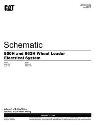
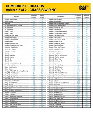
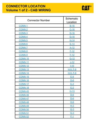
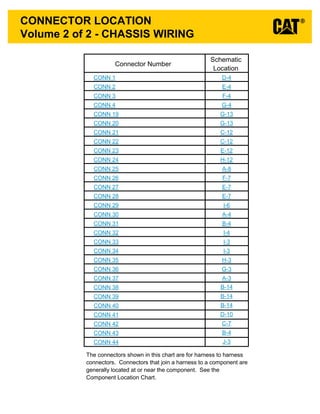
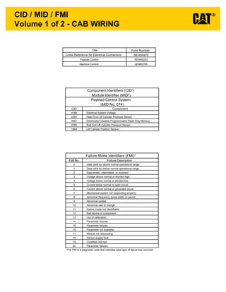
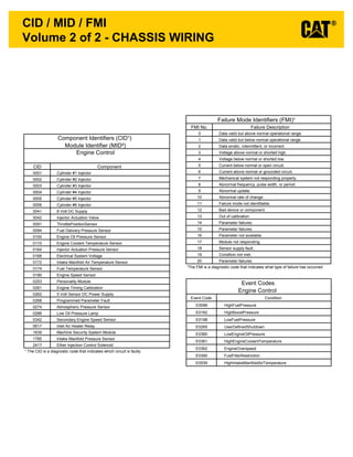
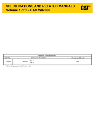
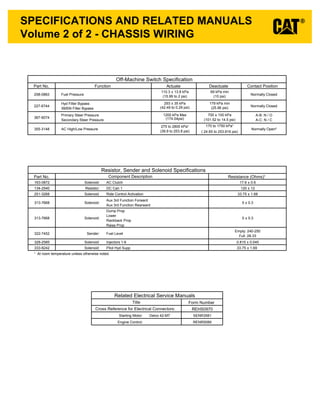
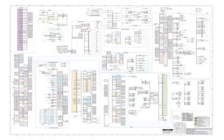
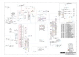
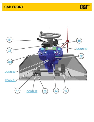
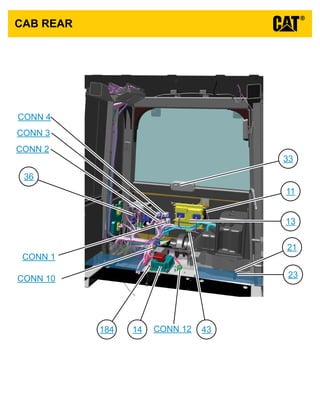
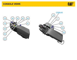
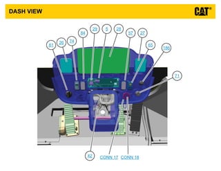
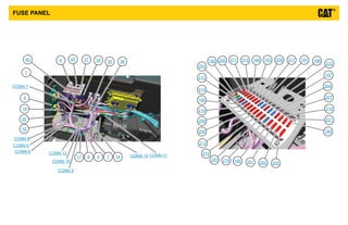
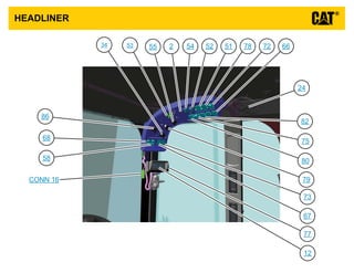
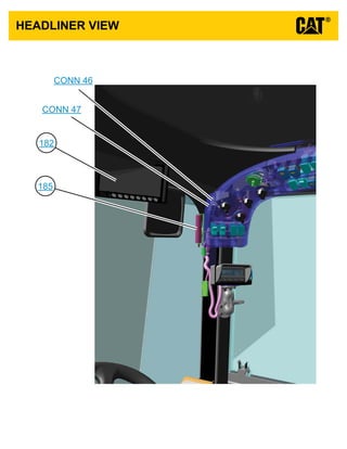
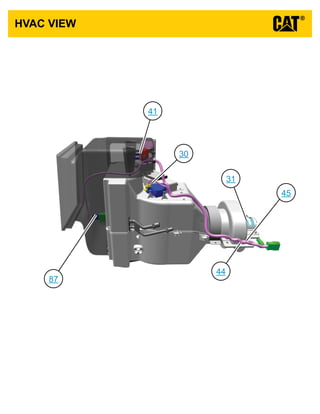
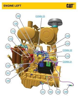
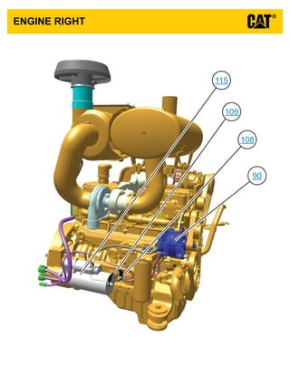
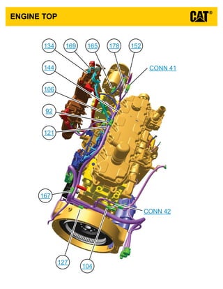
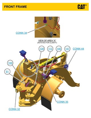
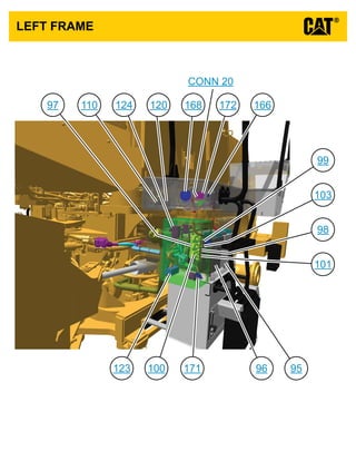
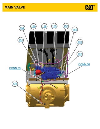
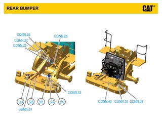
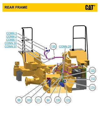
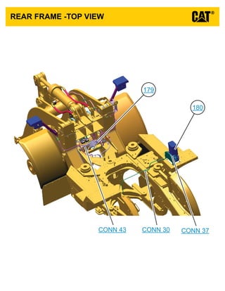
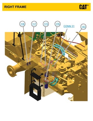
This document provides a schematic and component location guide for the electrical system of a 950H and 962H wheel loader. It includes 228 numbered components across two volumes - one for cab wiring and one for chassis wiring. The summary lists the component types and their schematic and machine locations to help technicians quickly navigate and service the electrical system.
Things to remember while upgrading the brakes of your carjennifermiller8137
Upgrading the brakes of your car? Keep these things in mind before doing so. Additionally, start using an OBD 2 GPS tracker so that you never miss a vehicle maintenance appointment. On top of this, a car GPS tracker will also let you master good driving habits that will let you increase the operational life of your car’s brakes.
What Exactly Is The Common Rail Direct Injection System & How Does It WorkMotor Cars International
Learn about Common Rail Direct Injection (CRDi) - the revolutionary technology that has made diesel engines more efficient. Explore its workings, advantages like enhanced fuel efficiency and increased power output, along with drawbacks such as complexity and higher initial cost. Compare CRDi with traditional diesel engines and discover why it's the preferred choice for modern engines.
What Does the PARKTRONIC Inoperative, See Owner's Manual Message Mean for You...Autohaus Service and Sales
Learn what "PARKTRONIC Inoperative, See Owner's Manual" means for your Mercedes-Benz. This message indicates a malfunction in the parking assistance system, potentially due to sensor issues or electrical faults. Prompt attention is crucial to ensure safety and functionality. Follow steps outlined for diagnosis and repair in the owner's manual.
In this presentation, we have discussed a very important feature of BMW X5 cars… the Comfort Access. Things that can significantly limit its functionality. And things that you can try to restore the functionality of such a convenient feature of your vehicle.
𝘼𝙣𝙩𝙞𝙦𝙪𝙚 𝙋𝙡𝙖𝙨𝙩𝙞𝙘 𝙏𝙧𝙖𝙙𝙚𝙧𝙨 𝙞𝙨 𝙫𝙚𝙧𝙮 𝙛𝙖𝙢𝙤𝙪𝙨 𝙛𝙤𝙧 𝙢𝙖𝙣𝙪𝙛𝙖𝙘𝙩𝙪𝙧𝙞𝙣𝙜 𝙩𝙝𝙚𝙞𝙧 𝙥𝙧𝙤𝙙𝙪𝙘𝙩𝙨. 𝙒𝙚 𝙝𝙖𝙫𝙚 𝙖𝙡𝙡 𝙩𝙝𝙚 𝙥𝙡𝙖𝙨𝙩𝙞𝙘 𝙜𝙧𝙖𝙣𝙪𝙡𝙚𝙨 𝙪𝙨𝙚𝙙 𝙞𝙣 𝙖𝙪𝙩𝙤𝙢𝙤𝙩𝙞𝙫𝙚 𝙖𝙣𝙙 𝙖𝙪𝙩𝙤 𝙥𝙖𝙧𝙩𝙨 𝙖𝙣𝙙 𝙖𝙡𝙡 𝙩𝙝𝙚 𝙛𝙖𝙢𝙤𝙪𝙨 𝙘𝙤𝙢𝙥𝙖𝙣𝙞𝙚𝙨 𝙗𝙪𝙮 𝙩𝙝𝙚 𝙜𝙧𝙖𝙣𝙪𝙡𝙚𝙨 𝙛𝙧𝙤𝙢 𝙪𝙨.
Over the 10 years, we have gained a strong foothold in the market due to our range's high quality, competitive prices, and time-lined delivery schedules.
Symptoms like intermittent starting and key recognition errors signal potential problems with your Mercedes’ EIS. Use diagnostic steps like error code checks and spare key tests. Professional diagnosis and solutions like EIS replacement ensure safe driving. Consult a qualified technician for accurate diagnosis and repair.
Comprehensive program for Agricultural Finance, the Automotive Sector, and Empowerment . We will define the full scope and provide a detailed two-week plan for identifying strategic partners in each area within Limpopo, including target areas.:
1. Agricultural : Supporting Primary and Secondary Agriculture
• Scope: Provide support solutions to enhance agricultural productivity and sustainability.
• Target Areas: Polokwane, Tzaneen, Thohoyandou, Makhado, and Giyani.
2. Automotive Sector: Partnerships with Mechanics and Panel Beater Shops
• Scope: Develop collaborations with automotive service providers to improve service quality and business operations.
• Target Areas: Polokwane, Lephalale, Mokopane, Phalaborwa, and Bela-Bela.
3. Empowerment : Focusing on Women Empowerment
• Scope: Provide business support support and training to women-owned businesses, promoting economic inclusion.
• Target Areas: Polokwane, Thohoyandou, Musina, Burgersfort, and Louis Trichardt.
We will also prioritize Industrial Economic Zone areas and their priorities.
Sign up on https://profilesmes.online/welcome/
To be eligible:
1. You must have a registered business and operate in Limpopo
2. Generate revenue
3. Sectors : Agriculture ( primary and secondary) and Automative
Women and Youth are encouraged to apply even if you don't fall in those sectors.
5 Warning Signs Your BMW's Intelligent Battery Sensor Needs AttentionBertini's German Motors
IBS monitors and manages your BMW’s battery performance. If it malfunctions, you will have to deal with an array of electrical issues in your vehicle. Recognize warning signs like dimming headlights, frequent battery replacements, and electrical malfunctions to address potential IBS issues promptly.
"Trans Failsafe Prog" on your BMW X5 indicates potential transmission issues requiring immediate action. This safety feature activates in response to abnormalities like low fluid levels, leaks, faulty sensors, electrical or mechanical failures, and overheating.
Core technology of Hyundai Motor Group's EV platform 'E-GMP'Hyundai Motor Group
What’s the force behind Hyundai Motor Group's EV performance and quality?
Maximized driving performance and quick charging time through high-density battery pack and fast charging technology and applicable to various vehicle types!
Discover more about Hyundai Motor Group’s EV platform ‘E-GMP’!
What Does the Active Steering Malfunction Warning Mean for Your BMWTanner Motors
Discover the reasons why your BMW’s Active Steering malfunction warning might come on. From electrical glitches to mechanical failures and software anomalies, addressing these promptly with professional inspection and maintenance ensures continued safety and performance on the road, maintaining the integrity of your driving experience.
Why Is Your BMW X3 Hood Not Responding To Release CommandsDart Auto
Experiencing difficulty opening your BMW X3's hood? This guide explores potential issues like mechanical obstruction, hood release mechanism failure, electrical problems, and emergency release malfunctions. Troubleshooting tips include basic checks, clearing obstructions, applying pressure, and using the emergency release.
1. Click here to view the
Schematic Symbols
and Definitions page
INTERACTIVE SCHEMATIC
The Bookmarks panel will allow you to
quickly navigate to points of interest.
Click on any text that is BLUE and
underlined. These are hyperlinks
that can be used to navigate the
schematic and machine views.
When only one callout is showing on a
machine view, clicking on this button will
make all of the callouts visible. This
button is located in the top right corner
of every machine view page.
VIEW ALL CALLOUTS
Cover Page
Tables
Schematic
Machine Views
Component
Connector
Chassis View
Cab View
Engine View
Features
Options
Bookmarks X
EC-C3
EC-C2 E-C60
EC-C1
E-C61
To set your screen resolution do the following:
RIGHT CLICK on the DESKTOP.
Select PROPERTIES.
CLICK the SETTINGS TAB.
MOVE THE SLIDER under SCREEN RESOLUTION
until it shows 1024 X 768.
CLICK OK to apply the resolution.
*This document is best viewed at a
screen resolution of 1024 X 768.
*Due to different monitor sizes and PDF reader preferences
there may be some variance in linked schematic locations
FUNCTION
Zoom In
HOTKEYS (Keyboard Shortcuts)
Zoom Out
Fit to Page
Hand Tool
“CTRL” / “+”
KEYS
“CTRL” / “-”
“CTRL” / “0” (zero)
“SPACEBAR” (hold down)
Find “CTRL” / “F”
Pressure
Switch
Temperature
Switch
Level
Switch
Flow
Switch Circuit Breaker
T
ELECTRICAL SYMBOLS
Spring
(Adjustable)
Variability
Fluid
Conditioner
Pump
or Motor
BASIC HYDRAULIC
COMPONENT SYMBOLS
Click here to save a copy of
this interactive schematic
to your desktop
Search “CTRL” / “SHIFT” / “F”
2. SCHEMATIC SYMBOLS AND DEFINITIONS
HYDRAULIC SYMBOLS - ELECTRICAL
Transducer
(Fluid)
Transducer
(Gas / Air)
G
Generator Electrical
Wire
Pressure
Switch
M
Electric
Motor
Pressure Switch
(Adjustable)
Temperature
Switch
Pressure
Switch
Temperature
Switch
Level
Switch
Flow
Switch Circuit Breaker
T
ELECTRICAL SYMBOLS
Spring
Control
Valves
Restriction Line Restriction
(Fixed)
2-Section
Pump
MAIN AUX.
Spring
(Adjustable)
Variability
Line Restriction
(Variable)
Pressure
Compensation
Pump: Variable and
Pressure Compensated
Hydraulic Pneumatic
Energy Triangles
Fluid
Conditioner
Attachment
Pump
or Motor
BASIC HYDRAULIC
COMPONENT SYMBOLS
Line Restriction
Variable and Pressure
Compensated
Vented Pressurized Return Above Fluid Level Return Below Fluid Level
FLUID STORAGE RESERVOIRS
Pressure Temperature Flow
MEASUREMENT
Unidirectional Bidirectional
ROTATING SHAFTS
One Position Two Position Three Position
Two-way Three-Way Four-Way
ENVELOPES
PORTS
CONTROL
Basic
Symbol
Spring
Loaded
Normal Position
A B
P T
A B
P T
Shifted Position Infinite Position
Shuttle Pilot
Controlled
VALVES
CHECK
Solenoid
or Manual
Solenoid
and Pilot
Solenoid and
Pilot or Manual
Solenoid Servo Thermal Detent
COMBINATION CONTROLS
T
Fuse: A component in an electrical circuit that will open the circuit if too much current flows through it.
Switch (Normally Open): A switch that will close at a specified point (temp, press, etc.). The circle indicates
that the component has screw terminals and a wire can be disconnected from it.
Switch (Normally Closed): A switch that will open at a specified point (temp, press, etc.).
No circle indicates that the wire cannot be disconnected from the component.
Ground (Wired): This indicates that the component is connected to a grounded wire.
The grounded wire is fastened to the machine.
Ground (Case): This indicates that the component does not have a wire connected to ground.
It is grounded by being fastened to the machine.
Reed Switch: A switch whose contacts are controlled by a magnet. A magnet closes the contacts of
a normally open reed switch; it opens the contacts of a normally closed reed switch.
Sender: A component that is used with a temperature or pressure gauge.
The sender measures the temperature or pressure.
Its resistance changes to give an indication to the gauge of the temperature or pressure.
Relay (Magnetic Switch): A relay is an electrical component that is activated by electricity.
It has a coil that makes an electromagnet when current flows through it.
The electromagnet can open or close the switch part of the relay.
Solenoid: A solenoid is an electrical component that is activated by electricity.
It has a coil that makes an electromagnet when current flows through it.
The electromagnet can open or close a valve or move a piece of metal that can do work.
Magnetic Latch Solenoid: An electrical component that is activated by electricity and held latched by a
permanent magnet. It has two coils (latch and unlatch) that make electromagnet
when current flows through them. It also has an internal switch that places
the latch coil circuit open at the time the coil latches.
BASIC ELECTRICAL COMPONENT SYMBOLS
Push-pull Lever PedalGeneral Manual Push Button SpringManual Shutoff
MANUAL CONTROL
External Return Internal Return
Simplified Complete
Internal
Supply Pressure
RELEASED PRESSURE
REMOTE SUPPLY PRESSURE
PILOT CONTROL
Spring Loaded Gas Charged
ACCUMULATORS
Crossing Joining
LINES
Double ActingSingle Acting
CYLINDERS
Unidirectional
Bidirectional
FIXED DISPLACEMENT
VARIABLE DISPLACEMENT
NON- COMPENSATED
PUMPS
Unidirectional
Bidirectional
Unidirectional
Bidirectional
FIXED DISPLACEMENT
VARIABLE DISPLACEMENT
NON- COMPENSATED
MOTORS
Unidirectional
Bidirectional
Two
Position
Infinite
Positioning
FLOW IN ONE
DIRECTION
FLOW ALLOWED IN
EITHER DIRECTION
Three
Position
CROSS
FLOW
PARALLEL
FLOW
INTERNAL PASSAGEWAYS
1
2
AG-C4
111-7898
L-C12
3E-5179
9X-1123
Component
Part Number
Pin or Socket Number
Part Number: for
Connector Plug
Harness Identification Letter(s): (A, B, C, AA, AB, AC, ...)
Plug
325-AG135 PK-14
Wire Color
Wire Gauge
Receptacle
1
1
2
2
Sure-Seal connector: Typical representation
of a Sure-Seal connector. The plug and receptacle
contain both pins and sockets.
Deutsch connector: Typical representation
of a Deutsch connector. The plug contains all
sockets and the receptacle contains all pins.
Fuse (5 Amps)
5A
Harness identification code:
This example indicates wire group 325,
wire 135 in harness "AG".
L-C12
3E-5179
Wire, Cable, or Harness Assembly Identification:
Includes Harness Identification Letters and Harness
Connector Serialization Codes (see sample).
Harness Connector Serialization Code: The "C" stands for
"Connector" and the number indicates which connector in the
harness (C1, C2, C3, ...)
HARNESS AND WIRE SYMBOLS
7. Volume 2 of 2 - CHASSIS WIRING
CONNECTOR LOCATION
Connector Number
Schematic
Location
CONN 1 D-4
CONN 2 E-4
CONN 3 F-4
CONN 4 G-4
CONN 19 G-13
CONN 20 G-13
CONN 21 C-12
CONN 22 C-12
CONN 23 E-12
CONN 24 H-12
CONN 25 A-8
CONN 26 F-7
CONN 27 E-7
CONN 28 E-7
CONN 29 I-6
CONN 30 A-4
CONN 31 B-4
CONN 32 I-4
CONN 33 I-3
CONN 34 I-3
CONN 35 H-3
CONN 36 G-3
CONN 37
CONN 38
CONN 39
CONN 40
CONN 41
CONN 42
CONN 43
CONN 44
A-3
B-14
B-14
B-14
D-10
C-7
B-4
J-3
The connectors shown in this chart are for harness to harness
connectors. Connectors that join a harness to a component are
generally located at or near the component. See the
Component Location Chart.
8. Volume 1 of 2 - CAB WIRING
CID / MID / FMI
CID Component
0168 Electrical System Voltage
0364 Head End Lift Cylinder Pressure Sensor
0591 Electrically Erasable Programmable Read Only Memory
0769 Rod End Lift Cylinder Pressure Sensor
1964 Lift Cylinder Position Sensor
Component Identifiers (CID¹)
Module Identifier (MID²)
Payload Control System
(MID No. 074)
FMI No. Failure Description
0 Data valid but above normal operational range.
1 Data valid but below normal operational range.
2 Data erratic, intermittent, or incorrect.
3 Voltage above normal or shorted high.
4 Voltage below normal or shorted low.
5 Current below normal or open circuit.
6 Current above normal or grounded circuit.
7 Mechanical system not responding properly.
8 Abnormal frequency, pulse width, or period.
9 Abnormal update.
10 Abnormal rate of change.
11 Failure mode not identifiable.
12 Bad device or component.
13 Out of calibration.
14 Parameter failures.
15 Parameter failures.
16 Parameter not available.
17 Module not responding.
18 Sensor supply fault.
19 Condition not met.
20 Parameter failures.
¹The FMI is a diagnostic code that indicates what type of failure has occurred.
Failure Mode Identifiers (FMI)¹
Form Number
REHS0970
Payload Control: RENR6293
Machine Control: UENR0795
Title
Cross Reference for Electrical Connectors:
9. Volume 2 of 2 - CHASSIS WIRING
CID / MID / FMI
CID Component
0001 Cylinder #1 Injector
0002 Cylinder #2 Injector
0003 Cylinder #3 Injector
0004 Cylinder #4 Injector
0005 Cylinder #5 Injector
0006 Cylinder #6 Injector
0041 8 Volt DC Supply
0042 Injector Actuation Valve
0091 ThrottlePositionSensor
0094 Fuel Delivery Pressure Sensor
0100 Engine Oil Pressure Sensor
0110 Engine Coolant Temperature Sensor
0164 Injector Actuation Pressure Sensor
0168 Electrical System Voltage
0172 Intake Manifold Air Temperature Sensor
0174 Fuel Temperature Sensor
0190 Engine Speed Sensor
0253 Personality Module
0261 Engine Timing Calibration
0262 5 Volt Sensor DC Power Supply
0268 Programmed Parameter Fault
0274 Atmospheric Pressure Sensor
0286 Low Oil Pressure Lamp
0342 Secondary Engine Speed Sensor
0617 Inlet Air Heater Relay
1639 Machine Security System Module
1785 Intake Manifold Pressure Sensor
2417 Ether Injection Control Solenoid
Component Identifiers (CID¹)
Module Identifier (MID²)
Engine Control
¹ The CID is a diagnostic code that indicates which circuit is faulty.
FMI No. Failure Description
0 Data valid but above normal operational range.
1 Data valid but below normal operational range.
2 Data erratic, intermittent, or incorrect.
3 Voltage above normal or shorted high.
4 Voltage below normal or shorted low.
5 Current below normal or open circuit.
6 Current above normal or grounded circuit.
7 Mechanical system not responding properly.
8 Abnormal frequency, pulse width, or period.
9 Abnormal update.
10 Abnormal rate of change.
11 Failure mode not identifiable.
12 Bad device or component.
13 Out of calibration.
14 Parameter failures.
15 Parameter failures.
16 Parameter not available.
17 Module not responding.
18 Sensor supply fault.
19 Condition not met.
20 Parameter failures.
¹The FMI is a diagnostic code that indicates what type of failure has occurred.
Failure Mode Identifiers (FMI)¹
Event Code Condition
E0096 HighFuelPressure
E0162 HighBoostPressure
E0198 LowFuelPressure
E0265 UserDefinedShutdown
E0360 LowEngineOilPressure
E0361 HighEngineCoolantTemperature
E0362 EngineOverspeed
E0390 FuelFilterRestriction
E0539 HighIntakeManifoldAirTemperature
Event Codes
Engine Control
10. Volume 1 of 2 - CAB WIRING
SPECIFICATIONS AND RELATED MANUALS
Part No. Resistance (Ohms)¹
134-2540 Resistor:
Can A
Can B
120 ± .1
¹ At room temperature unless otherwise noted.
Resistor Specifications
Component Description
11. Volume 2 of 2 - CHASSIS WIRING
SPECIFICATIONS AND RELATED MANUALS
Part No. Function Actuate Deactuate Contact Position
110.3 ± 13.8 kPa 69 kPa min
293 ± 35 kPa 179 kPa min
1200 kPa Max 700 ± 100 kPa
275 to 2800 kPa¹
(39.9 to 253.8 psi)
(101.52 to 14.5 psi)
(15.99 to 2 psi) (10 psi)
(25.96 psi)(42.49 to 0.29 psi)
(174.04psi)
170 to 1750 kPa¹
( 24.65 to 253.816 psi)
Off-Machine Switch Specification
AC High/Low Pressure355-3148 Normally Open²
367-9074
227-6744
258-0883 Fuel Pressure
Hyd Filter Bypass
XMSN Filter Bypass
Primary Steer Pressure
Secondary Steer Pressure
Normally Closed
Normally Closed
A-B: N / O
A-C: N / C
Part No. Resistance (Ohms)¹
163-0872 Solenoid: AC Clutch 17.6 ± 0.6
134-2540 Resistor: DC Can 1 120 ± 12
251-3268 Solenoid: Ride Control Activation 33.75 ± 1.68
313-7668 Solenoid:
Aux 3rd Function Forward
Aux 3rd Function Rearward
5 ± 0.3
313-7668 Solenoid:
Dump Prop
Lower
Rackback Prop
Raise Prop
5 ± 0.3
322-7452 Sender: Fuel Level
Empty: 240-250
Full: 28-33
328-2585 Solenoid: Injectors 1-6 0.815 ± 0.045
333-8242 Solenoid: Pilot Hyd Supp 33.75 ± 1.69
¹ At room temperature unless otherwise noted.
Resistor, Sender and Solenoid Specifications
Component Description
Form Number
REHS0970
Starting Motor: Delco 42-MT SENR3581
Engine Control: RENR5089
Title
Related Electrical Service Manuals
Cross Reference for Electrical Connectors: