Types of styli and their standards
•
0 likes•183 views

There are different types of pickups and styli in surface roughness measurements

Recommended
More Related Content
What's hot
What's hot (20)
Viewers also liked
Similar to Types of styli and their standards
Similar to Types of styli and their standards (20)
More from Marwan Shehata
More from Marwan Shehata (19)
Recently uploaded
Recently uploaded (20)
Types of styli and their standards
- 1. Types of styli and their standards Name: Marwan Shehata Mohamed Zeitoun No: 159 Sec: 7
- 2. PAGE 1 What is stylus? According to British standard definition: - A contact (stylus) instrument of consecutive profile transformation used for the measurement of surface roughness parameters according to system M (the mean line system). In Figure 9, a schematic illustration is depicted of the basic components for a typical surface texture measuring instrument. The stylus traverses across the surface and the transducer converts its vertical movements into an electrical signal. This signal is then amplified for subsequent processing, or output to operate a pen recorder. The required parameter value is subsequently derived from the filtered signal, having previously been displayed on screen. In general, the profile is the result of the stylus tracing the movement across the surface under test, the contacting of consecutive points of the profile being spaced in time. Therefore this relationship between movement and time is closely associated with its "cut -off". "Cut -off" refers to the limiting wavelength at which components of the profile are passed nominally unchanged by a filter. Types of styli according to Geometry The stylus is normally either conical with a spherical tip (see Figure 10), or a four-sided pyramid with a truncated flat tip. The conical type of styli have a cone angle of either 60° or 90°, with a tip radius ranging from less than 0.1 μm to 12 μm in size. A pyramidal stylus tends to be approximately 2 μm wide in the traverse direction, but is normally wider transversely to the direction of travel, giving the tip greater strength (see Figure below left). The sharp-pointed 0.1 μm wide pyramidal stylus (Figure below right), is utilized on the Taylor Hobson "Talystep" and "Nanostep" instruments. However, in use the edges of a pyramidal tip tend to become rounded with wear; conversely, the spherical tip version develops a flat, so the distinction between the two profile geometries becomes less marked with time. If a stylus tip becomes damaged during use, this results in a considerable increase in its width, leading to potentially very serious measuring errors. Typical stylus geometries Scanning electron photomicrograph of a stylus (5 μm point radius) on a surface
- 3. PAGE 2 This significant size differential enables the stylus to penetrate into quite narrow valleys, although its finite size affects the accuracy with which the surface profile can be traced. These stylus profile and size limitations influence the following: - distortion of peak shape: as the spherical stylus traverses over a sharp peak, the point of contact shifts across the stylus - from one side to the other (Figure below). This results in the stylus having to follow a path which is more rounded than the peak, but due to the stylus being raised to its full height when at the crest the true peak height is measured - penetration into valleys: due to the tip's size, it may not be able to completely penetrate to deep and narrow valley bottoms - re-entrant features cannot be traced: whenever a stylus encounters a re-entrant feature (Figure below detail) the stylus tip loses partial contact with the profile and as a result will remove this feature from the trace. Stylus geometry and its mechanical filtering effect on surface texture. IIlustrates how the use of a larger-radius stylus reduces the apparent amplitude of closely spaced irregularities.
- 4. PAGE 3 Types of pick up according to components 1- A stylus with skid/shoe: The transducer assembly can incorporate both a stylus and skid, with the skid offering a local datum for this transducer and with that of the surface. Moreover, the skid provides a local datum for the stylus with respect to its vertical and horizontal motion. Therefore, with the skid's large curved radius to that of the relatively small surface under test, it rides along the surface being measured providing a "local datum”. As long as the skid's radius is greater than the peak spacing, the apparent line of movement of this skid will be virtually a straight line. Under such surface transducer conditions as the vertical skid moves from crest to crest, its relative horizontal skid motion with respect to the test surface can be ignored, as the skid's vertical motion is virtually insignificant. However, once the crests in the surface under test become more widely spaced, this horizontal crest spacing tends to introduce a significant amount of vertical skid motion. If the skid's vertical motion affects the subsequent surface texture results, it is then preferable to use the instrument in the "skidless mode”. ACCORDING TO ISO 3274:1975: - Skid radius: If a skid is employed, its radius in the direction of the trace should be no less than 50 times the nominal cut-off wavelength used. If two simultaneously operative skids are used, their radii should be no less than eight times the nominal cut-off wavelength. - Skid force: The force exerted by the skid on the surface to be measured should be no greater than 0,5 N. The "phase effects" when using a skid 2- Skidless type To achieve skidless operation and minimize the unwanted effects of vertical skid motion which might otherwise interfere with the results, the skid must be removed, then by utilizing the instrument's in-built straight edge as a "sliding datum" the surface assessment can be undertaken. The main reason for employing skidless pickups are that they do not eliminate the contributions of waviness and profile errors from the measured topography - which the skid obviously does - and often waviness, in particular, is important to the manufacturing process and must be included in the assessment. The skidless technique provides an undistorted assessment of the actual profile, the proviso being that the reference surface has ideal form. Pick up According to ISO 3274:1996 pick-up is: Component which contains the tracing element with the stylus tip and the transducer. & Stylus tip is: Element which consists of a nominally right, circular cone of defined cone angle and of a nominally spherical tip of defined radius.
- 5. PAGE 4 ANALOGUE TRANSEDUCERS A) Position-sensitive pick-ups Gives a signal proportional to displacement, even when the stylus is stationary. Output is independent of the speed at which the stylus is displaced and is only related to the position of the stylus within a permissible range of vertical movement. A big advantage of this type of pick -up is that it enables a true recording of waviness and profile to be obtained. B) Motion-sensitive pick-ups Produces an output only when the stylus is in motion, with the output being related to the speed at which the stylus is displaced, dropping to zero when stationary. If displacement is very slow, perhaps due to widely spaced waviness or to change in form, then the output for practical purposes is almost zero. This low output means that variations of waviness and form are excluded from the profile. These pick-ups tend to be utilized if instruments do not have recording facilities, such as some portable equipment. A) Position sensitive pick-ups B) Motion-sensitive pick-ups The variable-inductance pick-up, illustrated in Figure 36(ai), has been widely used for many years. The stylus is situated at one end of a beam pivoted at its center on knife edges, while at the opposite end an armature is carried which moves between two coils, changing the relative inductance. This pickup's operating principle is as follows: coils are connected in an AC bridge circuit (Figure 36aii) such that when the armature is centrally positioned between the bridge Pick-up Analogue Transeducer Position- sensitive Motion- sensitive Digital Transeducer Non-contact laser Phase grating interferometric
- 6. PAGE 5 it is balanced, giving no output. Movement of the armature unbalances the bridge, providing an output proportional to its displacement; the relative phase of the signal depends on the direction of movement. This signal is amplified and compared with that of the oscillator, to determine in which direction it has moved from the central (zero) position. It is necessary to utilize an oscillator to produce a constant AC output, because the pick-up - unlike a motion-sensitive pick- up (Figure 36b) - does not generate any output; it merely serves to modify the carrier. Simultaneously, the knife edges exert light pressure from a very weak spring acting on the beam, enabling subsequent stylus contact with the surface under test. The ligaments prevent unwanted motion of the beam in the horizontal plane, with the result that stylus movement is only possible normal to the surface being assessed. The piezoelectric pick-up (Figure 36b) has been widely used in the past, but now it tends to be used for the less sophisticated hand-held measuring instruments. When the stylus deforms the piezoelectric crystal, it has the property of developing a voltage across electrodes, the advantage being that it is virtually instantaneous. As the stylus follows the contours of the surface, the piezoelectric crystal distorts by bending a flexure that causes crystal compression and it becomes charged. The resulting charge is then amplified and electronically integrated, producing signals proportional to the surface profile. A piezoelectric transducer exerts a proportionally larger stylus force to that of an equivalent inductive transducer, with the former pick-up possibly damaging softer and more delicate surfaces. Standards used 1- British Standard BS 1134-1: 1988 Assessment of surface texture, Definitions 2- ISO 3274:1996 Geometrical Product Specifications (GPS) -- Surface texture: Profile method -- Nominal characteristics of contact (stylus) instruments. 3- Measuring conditions according to DIN EN ISO 4288
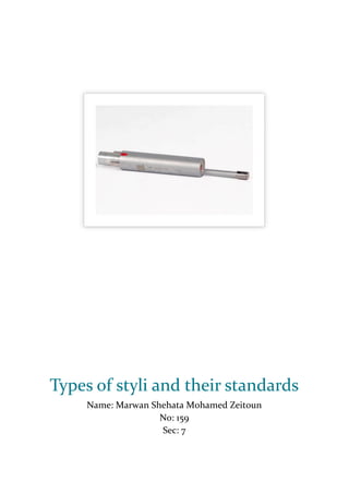
- 7. PAGE 6 For magnetic parts, what should we do to measure the surface roughness of a magnetic part? We should use the inductance method. An inductance pickup is used to measure the distance between the surface and the pickup. This measurement gives a parametric value that may be used to give a comparative roughness. However, this method is limited to measuring magnetic materials. The stylus of measurement should be of a non-magnetic material like Ruby… RUBY BALL STYLI These are suitable for the majority of probing applications. They incorporate highly spherical industrial ruby balls. Ruby is an extremely hard ceramic material, and hence the wear of stylus balls is minimized. It is also of low density which keeps the tip mass to minimum. This avoids unwanted probe triggers caused by machine motion or vibration. Ruby balls are available mounted on a variety of materials including non-magnetic stainless steel, ceramic and carbide, to maintain stiffness over the total range of styli So in brief: 1- We should use non-magnetic pickups and styli to prevent magnetic flux to interfere with the electrical signal otherwise we will get false readings 2- If we are using a ferromagnetic stylus, then we should increase the radius of the stylus to prevent more friction during measurement