Download to read offline

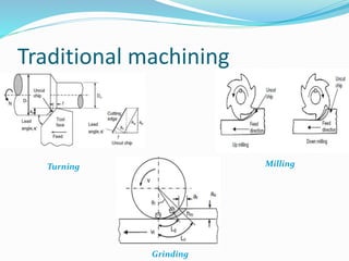
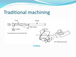
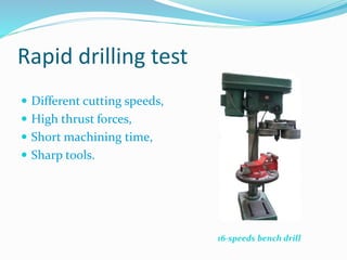
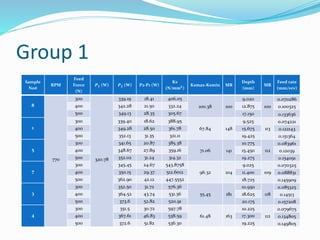
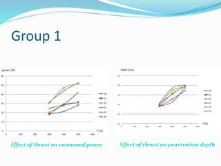
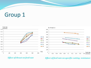
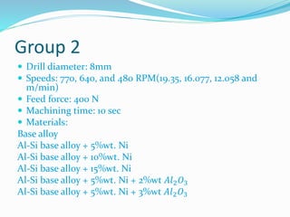
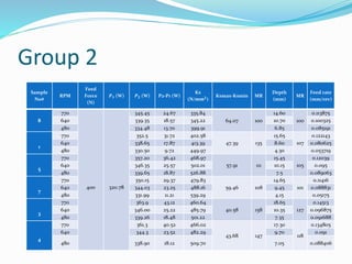
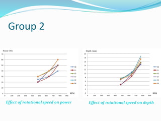
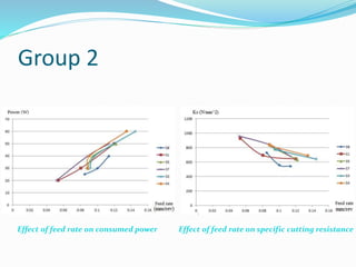
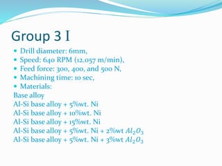
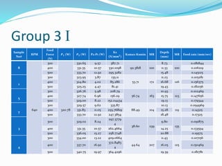
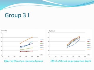
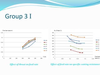
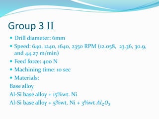
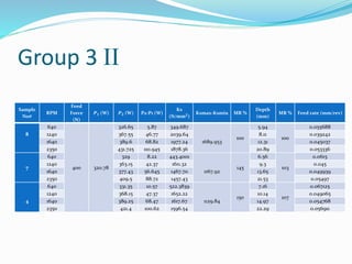
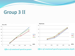
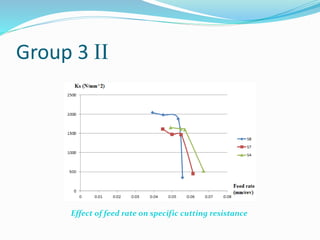
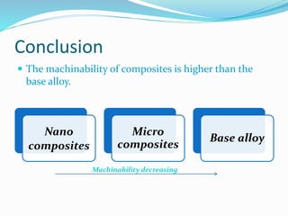
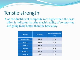
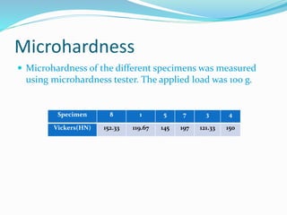


This document discusses a bachelor project on composites conducted by three students and supervised by Prof. Dr. Helmi Abdel Maksoud Youssef. It examines the machinability of aluminum-silicon alloy composites reinforced with nickel microparticles and aluminum oxide nanoparticles. Experiments were conducted to evaluate how drilling parameters like speed, feed force, and drill diameter affect power consumption, depth, and specific cutting resistance. Results showed that nano- and micro-composites had better machinability than the base alloy due to their higher ductility and strength. Microhardness was also measured for the different specimens.


![[IJET V2I4P3] Authors: N.Keerthi, N.Deepthi,N.Jaya Krishna](https://cdn.slidesharecdn.com/ss_thumbnails/ijet-v2i4p3-160810100959-thumbnail.jpg?width=640&height=640&fit=bounds)


