Download to read offline

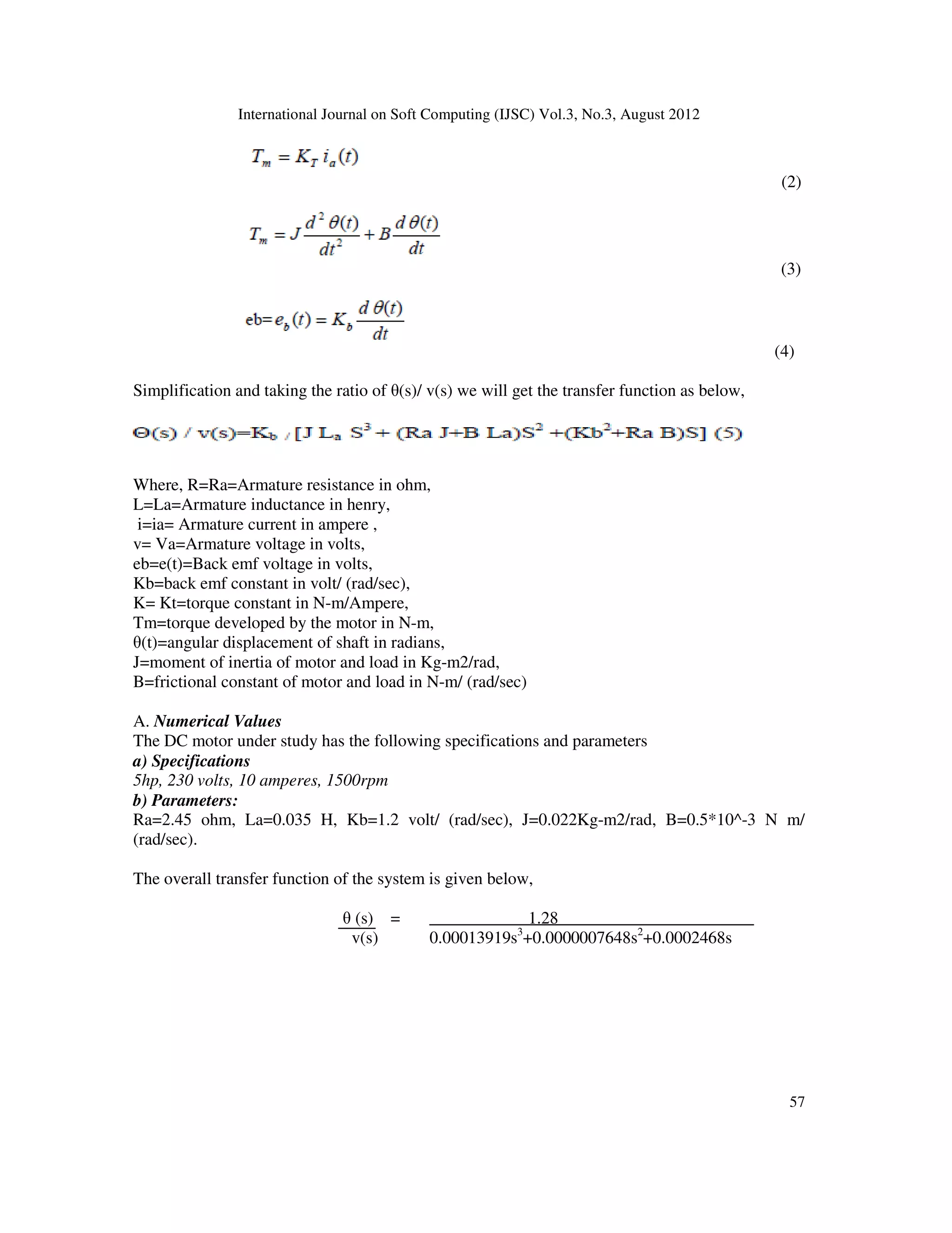
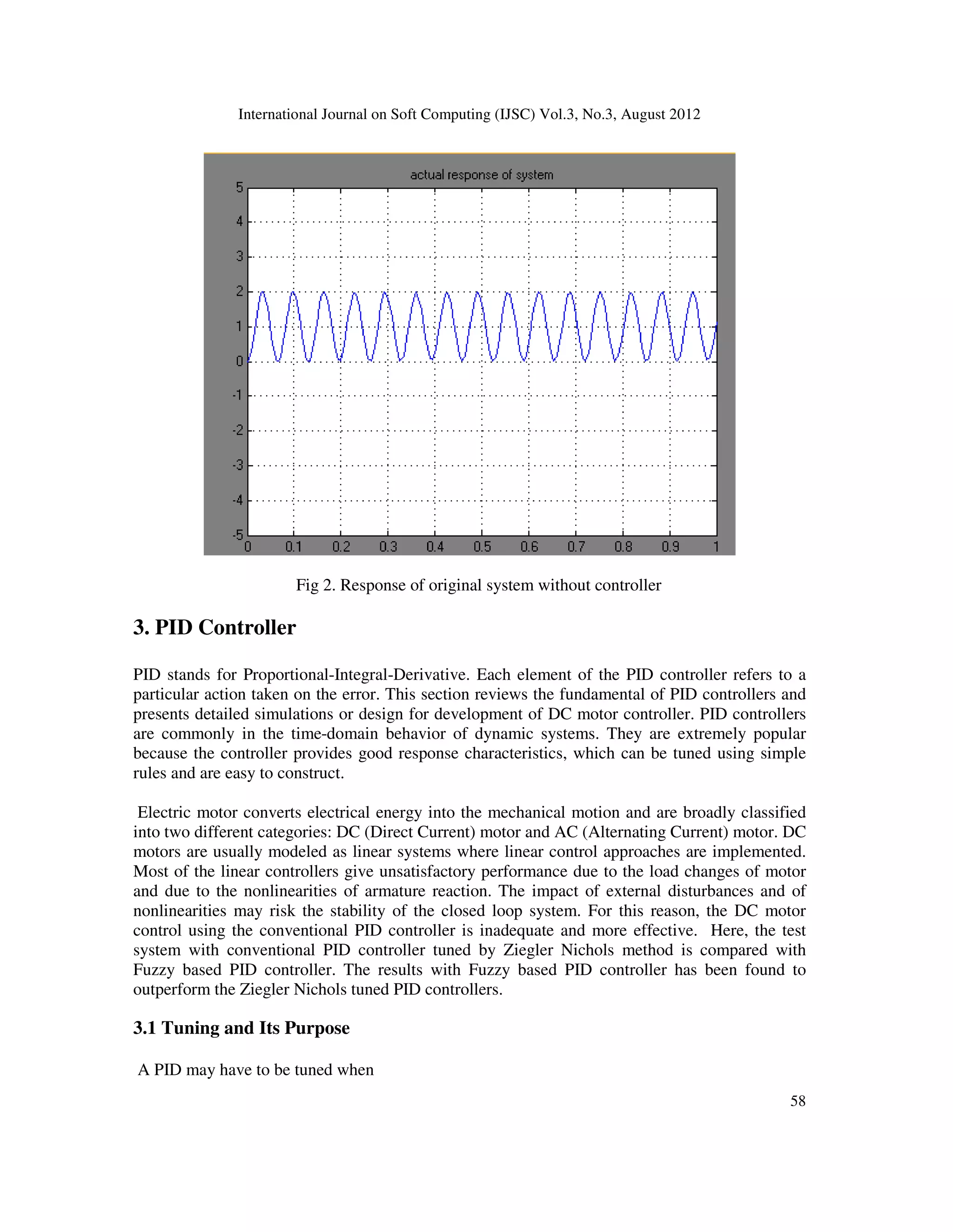

![International Journal on Soft Computing (IJSC) Vol.3, No.3, August 2012
62
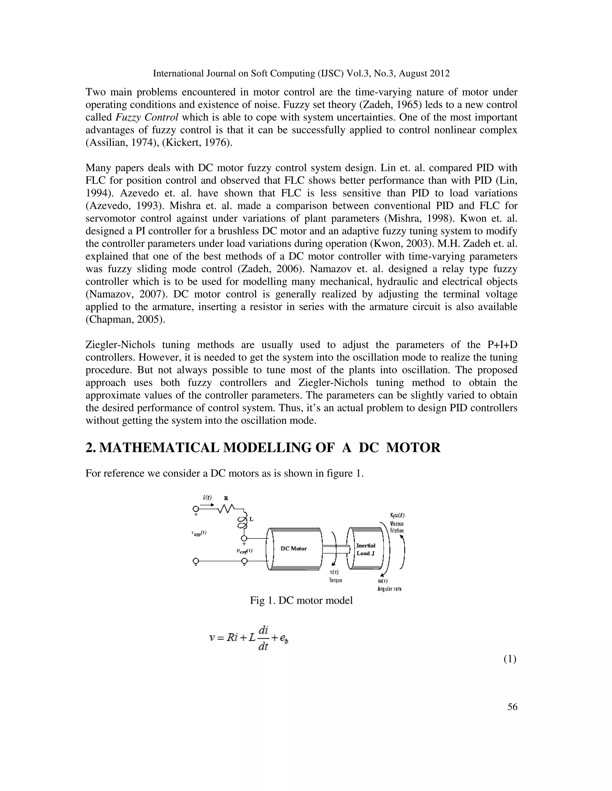
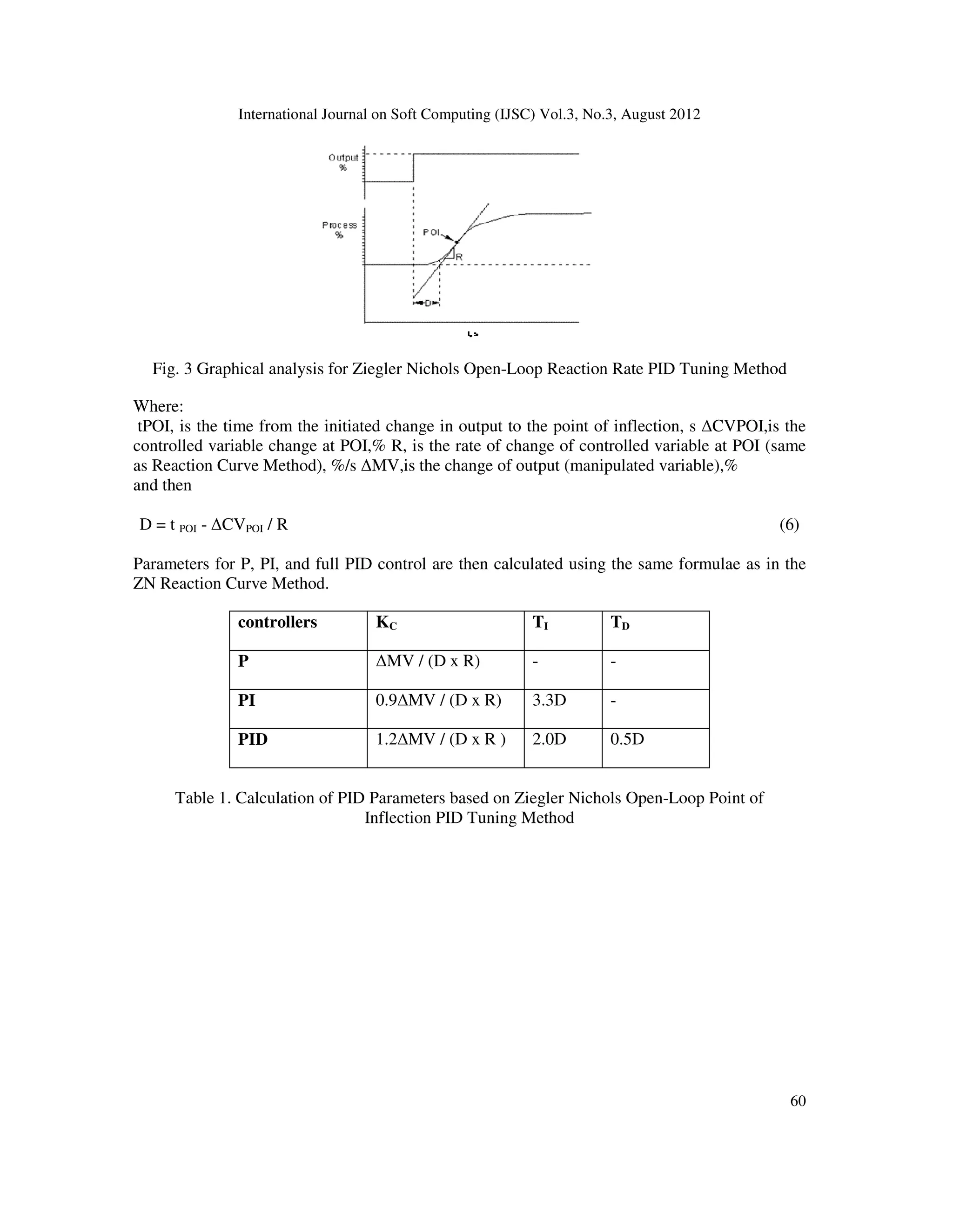
Fig 5. Response of the system with tuning based on stability margin
3.2 FUZZY LOGIC
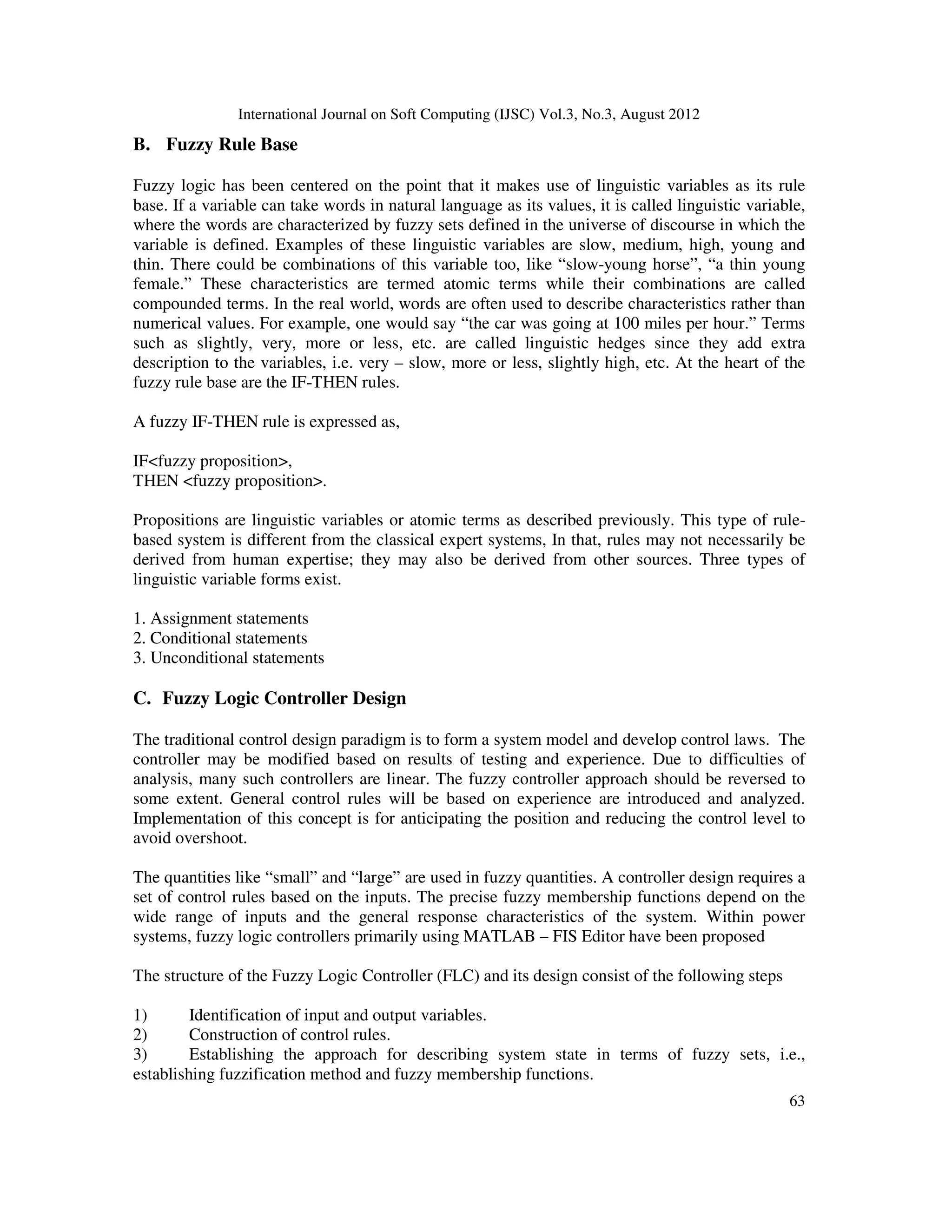
A. Introduction
Fuzzy logic is a derivative from classical Boolean logic and implements soft linguistic on a
continuous range of truth values to be defined between conventional binary. It can often be
considered a suspect of conventional set theory. Since fuzzy logic handles approximate
information in a systematic manner, it is ideal for controlling non-liner systems and fro modeling
complex systems where an inexact model exists or systems where ambiguity or vagueness is
common. A typical fuzzy system consists of a rule base, membership functions and an inference
procedure [9]. Today, fuzzy logic are found in a variety of control applications like chemical
process control, manufacturing and in such consumer products as washing machines, video
cameras and automobiles. Fuzzy logic is a suspect of conventional Boolean logic that has been
extended to handle the concept of partial truth- truth- values between “completely true” and
“completely false”.Fuzzy theory as a single theory, we should regard the process of fuzzification
as a methodology to generalize ANY specific theory from a crisp (discrete) to a fuzzy
(continuous) form. Thus, recently, researchers have also introduced “fuzzy calculus” and “fuzzy
differential equations”](https://image.slidesharecdn.com/3312ijsc05-220824093039-dcf762c1/75/Performance-based-Comparison-between-Various-Z-N-Tuninng-PID-and-Fuzzy-Logic-PID-Controller-in-Position-Control-System-of-DC-Motor-8-2048.jpg)

![International Journal on Soft Computing (IJSC) Vol.3, No.3, August 2012
66
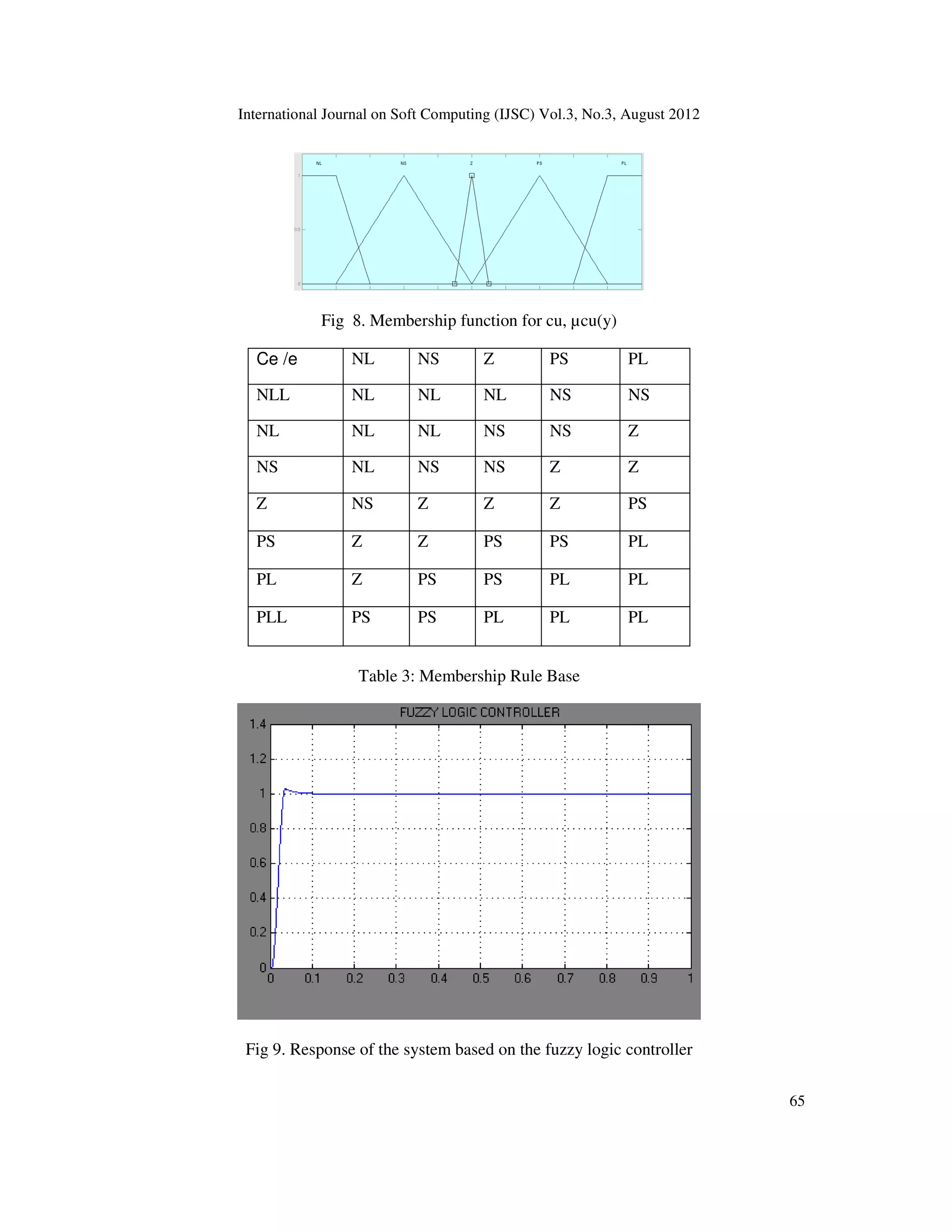
4. Performance Analysis
The most desirable performance requires the Controllers to have the smallest possible value for
the rise time, overshoot and the settling time. It is also required for the final value should be as
close as possible to the desired value which is unity. From the table, it can be seen that the fuzzy
logic controller can produce a desirable response performance with the use of only the
proportional, Integral and Derivative Component (PID). When compared to the conventional PID
controller, the fuzzy logic PID controller shows a better performance in terms of raise time while
it exhibits a slightly lesser performance in terms of peak value and settling time.
Performance metric
With controller (various PID tuning)
ZN-POI ZN-SM FLC
Raise time 0.017 0.0245 0.0218
Settling time 0.29 1.00 0.155
Peak value 1.0301 1.5765 1.025
Final value 1.000 1.000 0.9985
Over shoot 0.030 0.576 0.025
5. CONCLUSION
The designed PID with Fuzzy based has much faster response than response of the classical
method. However the Fuzzy logic designed PID is much better in terms of the peak value and the
settling time than the conventional method. Finally the fuzzy based PID controller provides much
better results compared to the conventional methods. In this paper, implementation of the fuzzy
based PID controller for the DC motor position control system is covered.
6. REFERENCES
[1] I.J.Nagrath and M.Gopal. 1999 Control systems engineering.
[2] O. Dwyer,.PI And PID Controller Tuning Rules For Time Delay Process: A Summary. Part 1: PI
Controller Tuning Rules.. , Proceedings Of Irish Signals And Systems Conference, June 1999.
[3] O. Montiel, R. Sepúlveda, P. Melin and O. Castillo, “Performance of a simple tuned Fuzzy controller
and a PID controller on a DC motor,” Procee. of IEEE (FOCI 2007), pp. 531-538, 2007.
[4] G. Haung and S. Lee, “PC based PID speed control in DC motor,” IEEE Conf. SALIP-2008, pp. 400-
408, 2008.
[5] Khongkoom N.,Kanchanathep A.,Nopnakeepong S., Tanuthong S.,Tunyasrirut S.,Kagawa
R.,“Control of the position DC servo motor by fuzzy logic,” TENCON 2000. Proceedings , 2000, 3
,pp. 354-357
[6] Tang K.S., Kim Fung Man, Guanrong Chen, Kwong S., “An optimal fuzzy PID controller,” Industrial
Electronics, IEEE Transactions on , 2001, 48, pp. 757 – 765](https://image.slidesharecdn.com/3312ijsc05-220824093039-dcf762c1/75/Performance-based-Comparison-between-Various-Z-N-Tuninng-PID-and-Fuzzy-Logic-PID-Controller-in-Position-Control-System-of-DC-Motor-12-2048.jpg)
![International Journal on Soft Computing (IJSC) Vol.3, No.3, August 2012
67
[7] K.J.Aström,T. Hägglund,C.C. Hang,and W. K. Ho, “Automatic tuning and adaptation for PID
controllers—A survey,”in Adaptive Systems in Control and Signal Processing, L. Dugard, M.
M’Saad, and I.D.Landau,Eds. Oxford,U.K.: Pergamon,2006, pp.371–376.
[8] Timothy J.Rose, 1997 “Fuzzy Logic with Engineering Applications”, Mc - GrawHill.Inc, New York
[9] Zadeh, M. H., Yazdian, A. and Mohamadian, M., Robust Position Control in DC Motor by Fuzzy
Sliding Mode Control. International Symposium on Power Electronics, Electrical Drives, Automation
and Motion (SPEEDAM 2006), 1413-1418, 2006.
[10] Arpit Goel, Ankit Uniyal, Anurag Bahuguna, Rituraj S. Patwal and Husain Ahmed “Performance
Comparison Of PID And Fuzzy Logic Controller Using Different Defuzzification Techniques For
Positioning Control Of DC Motors” Journal of Information Systems and Communication ISSN: 0976-
8742 & E-ISSN: 0976-8750, Volume 3, Issue 1, 2012, pp.-235-238.
[11] G. Haung and S. Lee, “PC based PID speed control in DC motor,” IEEE Conf. SALIP-2008, pp. 400-
408, 2008.
Authors
G.SUDHA was born in India. She received her B.E. degree in Electronics and
Instrumentation Engineering from Maharaja Engineering College, Avinashi and the M.E
degree in Process Control and Instrumentation from Annamalai University, Chidambaram
in India. Currently, she is working as Assistant Professor, Department of Electronics and
Instrumentation Engineering in Vivekanandha College of Technology for Women,
Tiruchengode, India. Her research interests include control system and artificial
intelligence techniques applications, Process Control.
Dr. R. Anita was born in India. She received her B.E. degree in Electrical and
Electronics Engineering from Government College Technology, Coimbatore and the
M.E degree in Applied Electronics from Coimbatore Institute of Technology,
Coimbatore in India and the Ph.D. degree from the Anna University, Chennai, India in
2004. Currently, she is working as a Professor & Head, Department of Electrical and
Electronics Engineering in Institute of Road and Transport Technology, Erode, India -
638 316. At present she is guiding more than 15 research scholars. One of them has been
awarded Ph.D. She has published 52 papers. Her research interests include condition
monitoring of power apparatus and systems, insulation engineering, control system and artificial
intelligence techniques applications in electric power engineering.](https://image.slidesharecdn.com/3312ijsc05-220824093039-dcf762c1/75/Performance-based-Comparison-between-Various-Z-N-Tuninng-PID-and-Fuzzy-Logic-PID-Controller-in-Position-Control-System-of-DC-Motor-13-2048.jpg)

This paper compares the performance of PID and fuzzy logic PID controllers in the position control system of a DC motor. It highlights the advantages of fuzzy logic control in handling uncertainties and achieving better response times than conventional PID controllers, particularly when tuned with the Ziegler-Nichols method. The study employs MATLAB Simulink for simulation, using predefined motor parameters and fuzzy rule sets to optimize control responses.