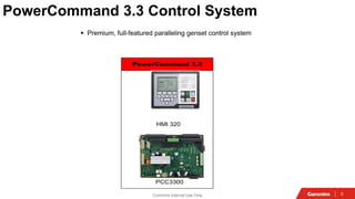
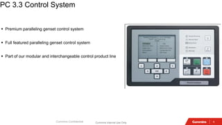
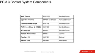
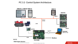
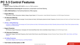
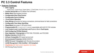
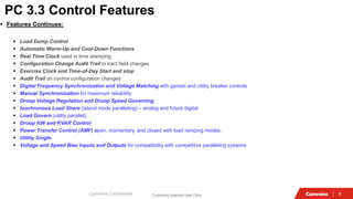
Cummins
Genset
Controller
2
Cummins Internal Use Only
Multi Level Genset Control Strategy
Low Featured (PS 0500)
Basic Standalone Control (PSP600)
Paralleling Control (PCC3.X)
5 10 20 50 100 200 500 1000 2000 2200 2500 2750 3750
GENSET KW RATING
Premium Standalone Control (PC 1.X)
Level 0
Level 1
Level 2
Level 3
Gas Control (PCC3.X) Level 4
3
Cummins Internal Use Only
PowerCommand 3.3 Control System
▪ Premium, full-featured paralleling genset control system
PowerCommand 3.3
HMI 320
PCC3300
4
Cummins Internal Use Only
PC 3.3 Control System
▪ Premium paralleling genset control system
▪ Full featured paralleling genset control system
▪ Part of our modular and interchangeable control product line
Cummins Confidential
5
Cummins Internal Use Only
PC 3.3 Control System Components
Cummins Confidential
Main Control PCC3300 Standard Scope
Operator Interface HMI220 or HMI320 HMI3320 Standard
Governor Power Stage AUX104 Standard Scope
AVR Power Stage & HMECM AUX105 Standard Scope
AC Bargraph HMI114 Standard Scope
Remote Annunciator HMI113 Optional
Auxiliary I/O AUX101 Optional
Service Tool InPower Service tool
6
Cummins Internal Use Only
PC 3.3 Control System Architecture
Cummins Confidential
PCC3300
HMI113
Network
(4 wire)
Modbus
AUX101
J1939
FAE Engine Version
Option
Inpower
(Service Tool)
Converter
Option
HMI114
HMI220 or HMI320
Option
AUX103
AUX105
J1939
7
Cummins Internal Use Only
Features:
▪ Digital 3 Phase Full Wave FET AVR for shunt or PMG excitation
▪ Digital Electronic Governing with temperature compensation and Smart Starting
▪ SAE J1939 Interface to Full Authority Electronic (FAE) engines
▪ Engine Metering
Oil Pressure, Coolant Temperature, Battery Voltage, Engine Speed, Oil Temperature, Intake Manifold Temperature, Full FAE Engine Parameters
▪ AC Alternator Metering
L-N and L-L Voltage (phase and average), Current (phase and total), Volt-Amperes (phase and total), Frequency, Kilowatts (phase and total), and Power Factor (phase
and total)
▪ AC Bus / Utility Metering
L-N and L-L Voltage (phase and average) and Current (phase and total), Volt-Amperes (phase and total), Kilowatts (phase and total), Power Factor (phase and total),
Frequency, and Syncroscope
▪ Engine Protection
Oil Pressure, Engine Temperature, Overspeed, DC Over/Under/Weak Volts, Fail to Crank/Start, Sensor Failure and Full FAE Engine Faults
▪ AC Alternator Protection
Over/Under Voltage, Over/Under Frequency, Over Current, Short Circuit, Loss of AC Sensing, Overload, Reverse Power, Reverse VAR’s, Sync Check, and Phase
Rotation
▪ AC Utility Protection
Over/Under Voltage, Under Frequency, and Phase Rotation
▪ Fault Codes and Description on HMI
PC 3.3 Control Features
8
Cummins Internal Use Only
▪ Features Continues:
▪ Data Logging
Engine Hours, Control Hours, Engine Starts, 32 Fault Codes, Kilowatt Hours, Load Profile
▪ Control Set-Up Without PC-Based Tool (InPower)
▪ Battle Short (fault bypass) function
▪ Configurable Glow Plug Control
▪ Configurable Cycle Cranking
▪ 12 and 24vdc Operation
▪ Easy Wiring connectors for factory connections, terminal blocks for field connections
▪ Configurable Time Delay Start/Stop
▪ Sleep Mode (low power in Off and/or Auto)
▪ Programmable I/O (4 inputs and 4 outputs) expandable with AUX101/102 modules
▪ Low Coolant Level, Low Fuel level, and Rupture Basin Fault Inputs
▪ Self-Configuring PCCNet Network
▪ Easy Upgrades / Downgrades to PCC1302, PCC2300, and PCC3300
▪ Modbus Interface (RS485 RTU)
▪ InPower Compatible (PC based service tool)
▪ Environmental Protection (NEMA 3R/IP53)
▪ NFPA110 Level 1 Compliant (with Remote Annunciator)
▪ UL508 Recognized / CSA Certified / CE Compliant
▪ AmpSentry with fault current regulation (UL listed)
▪ Oil Priming Pump Control
PC 3.3 Control Features
9
Cummins Internal Use Only
▪ Features Continues:
▪ Load Dump Control
▪ Automatic Warm-Up and Cool-Down Functions
▪ Real Time Clock used in time stamping
▪ Configuration Change Audit Trail to tract field changes
▪ Exercise Clock and Time-of-Day Start and stop
▪ Audit Trail on control configuration changes
▪ Digital Frequency Synchronization and Voltage Matching with genset and utility breaker controls
▪ Manual Synchronization for maximum reliability
▪ Droop Voltage Regulation and Droop Speed Governing
▪ Isochronous Load Share (island mode paralleling) – analog and future digital
▪ Load Govern (utility parallel)
▪ Droop KW and KVAR Control
▪ Power Transfer Control (AMF) open, momentary, and closed with load ramping modes.
▪ Utility Single
▪ Voltage and Speed Bias Inputs and Outputs for compatibility with competitive paralleling systems
Cummins Confidential
PC 3.3 Control Features
10
Cummins Internal Use Only
AmpSentry Feature
AmpSentry
When PowerCommand controls measure current in any phase as exceeding 110% of the generator set standby/ Prime rating a
current summing integral will be activated so that the generator will shut down based on the Ampsentry time current curve. The
green line in Figure 1 is the AmpSentry trip curve. This allows AmpSentry to protect the alternator and also the feeder cables
connected to the alternator provided they are rated for at least 100% of the full load current rating of the genset.
AmpSentry
Exceeds Phase
110 % S/ P DG
Set Rating
Summing
activated
DG SET
Shut Down
Based on
AS Time
Current
Curve
Safe Alternator
& Feeder
Cable
11
Cummins Internal Use Only
AmpSentry Feature
AmpSentry also has a fault current regulation feature. When the control measures current in any phase as
exceeding 300% of the generator set standby/ Prime rating the control recognizes that this is a fault condition and
begins to regulate current in the phase with the highest level of current to 300% of rated current. The purpose of
this is to allow a downstream OCPD to clear the fault, maintaining a coordinated system. AmpSentry’s
overcurrent protection function is in effect during a fault and will shut down the generator set based on the time
current curve if the fault is still active. Note that in Figure 1 as fault current decays to 300% of rated current
AmpSentry holds the current constant at that level until the line crosses the AmpSentry trip curve.
AmpSentry Fault
Current Regulation
Measures
Shut Down Holds
current until line
corsses Amp Syentry
trip Curve
Exceeding 300 %
Fault Reconizes
OCPD Maintain &
Coordinate &
Decompose to 300 %
12
Cummins Internal Use Only
AmpSentry Feature
AmpSentry Time Over Current curve. Includes symmetric and asymmetric fault current decrement curves
Control response and fault current decay resulting from a short circuit with AmpSentry Maintenance Mode active
13
Cummins Internal Use Only
AmpSentry Feature
AmpSentry Maintenance Mode
PowerCommand AmpSentry’s Maintenance Mode function acts in the same manner as maintenance
mode on a circuit breaker. When maintenance mode is enabled AmpSentry shuts down the generator set
(by shutting off fuel and excitation) as soon as it recognizes that current on any phase has exceeded
300% of the generator set rating. The short circuit shutdown event can also be mapped to one of the
customer configurable outputs of the control to shunt trip a breaker providing immediate isolation. Tests
have shown that excitation is shut off within 50 msec of the occurrence of the fault. In Figure 1, the red
line is activated as the trip curve when maintenance mode is enabled. Note that for current less than
300% of rated current the maintenance mode trip curve is the same as the standard AmpSentry trip
curve.
Figure 2 displays a current trace created during a test of AmpSentry Maintenance Mode. Note that in this
test the control recognized the fault within 38 msec of the fault occurrence and shut off the genset fuel
and excitation. The current decayed exponentially according to the transient time constant
14
Cummins Internal Use Only
Arc Flash
An arc flash (also called a flashover) is the light and heat
produced as part of an arc fault, a type of electrical explosion or
discharge that results from a low-impedance connection through
air to ground or another voltage phase in an electrical system.
Arc flash is distinctly different from the arc blast
An arcing fault is the flow of current through the air between
phase conductors or phase conductors and neutral or ground. An
arcing fault can release tremendous amounts of concentrated
radiant energy at the point of the arcing in a small fraction of a
second resulting in extremely high temperatures, a tremendous
pressure blast, and shrapnel hurling at high velocity.
Calories per Centimeter Squared (cal/cm2): This is a number
identifying the amount of energy that can be delivered to a point
at a particular distance from an arc flash
15
Cummins Internal Use Only
Battery Monitoring
16
Cummins Internal Use Only
Power Command(PCC 3.3)
Genset Performance on a Fault
AmpSentry regulates Fault Current
• Amps Peak on Faulted Phase
• Voltage on faulted phase collapses
• Power Command reduces excitation to
maintain 3X rated output
• Overvoltage avoided, coordination
maintained
10
1
0.1
0.05
1 10
3
AMPS (TIMES RATED)
TIME
(SECONDS)
ALTERNATOR THERMAL
DAMAGE CURVE
AMPSENTRY
PROTECTION
PHASE TO GROUND FAULT
THREE PHASE FAULT
100
17
Cummins Internal Use Only
Accessories
• Human machine interfaces
• Input / Output expansion module
• Service tools
• Manufacturing tools
Cummins Confidential
18
Cummins Internal Use Only
Cummins Confidential
Features:
▪ Back-Lit Graphics 320 x 240 (1/4 VGA) LCD Display
▪ English Text and Symbolic Overlay
▪ Multiple Language LCD Screens
▪ Dedicated Manual/Off/Auto function switches with mode LED’s and configurable access code (key switch)
▪ Optional Breaker Control Switches
▪ Status LED’s for genset running, remote start input active, not in auto, warning, and shutdown
▪ Genset Metering:
Based on Genset control
▪ 12 and 24vdc Operation
▪ Control Set-Up without PC-based tool (InPower)
▪ On Line Help Screens
▪ UL508 Recognized / CSA Certified / CE Compliant
▪ Multiple HMI's Per Genset (one local and one remote)
▪ Plug and Play operation with PCC1302, PCC2300, and PCC330 controls
▪ Save and Restore control configurations
▪ InPower Compatible (PC based service tool)
HMI320 Operator Interface
19
Cummins Internal Use Only
HMI 320 Operator Panel
Local Control Panel
0300-6315-02
Remote Control Panel
0300-6315-03
Fixed buttons
20
Cummins Internal Use Only
HMI114 AC Bargraph Interface
Features:
▪ Full Analog AC Metering
▪ Color LED Bargraph (green, red, and amber) to quickly indicate normal and abnormal operation
▪ Indication of:
▪ Three phase current
▪ Total KVA (PCC1302 compatible version)
▪ Total KW (PCC2300 and PCC3300 compatible version)
▪ Frequency
▪ Three Phase voltage
▪ 12 and 24vdc Operation
▪ UL508 Recognized / CSA Certified / CE Compliant
▪ Plug and Play operation with PC1302, PCC2300, PCC330, HMI220,and HMI320
▪ InPower Compatible (PC Based Service Tool)
21
Cummins Internal Use Only
Cummins Confidential
Features:
▪ Visual and Audible Annunciation for up to 20 genset faults.
▪ Meets NFPA Requirements
▪ Discrete Wire or Network Connection to the 1301
▪ Plug and Play Networking
▪ RS485 Connection (up to 4000 feet)
▪ Configurable LED’s (color, flash, horn)
▪ Four Configurable Relays for customer specified outputs
▪ 12 and 24vdc Operation
HMI113 Remote Annunciator
22
Cummins Internal Use Only
Cummins Confidential
Application of PC 3.3
▪ Sync Only
The sync only paralleling application type allows the genset synchronizer to be manually turned on through a hard wired input. One
application of this function would be for use with a closed transition transfer switch. See Figure 0-2 for operation details.
▪ Isolated Bus Only
The isolated bus only paralleling application type allows the genset to operate in parallel on a common bus with multiple gensets. See
Figure 0-3 for operating details.
▪ Utility Single
The utility single paralleling application type allows a single genset operate in parallel with a single utility source. Note that Utility
Single Mode Verify/Configurable Input #29 Switch must be connected to a switch input return to enable utility single. See Figure 0-4
and Figure 0-5 for operating details.
▪ Utility Multiple
The utility multiple application type allows the genset to operate on a common bus multiple gensets and in parallel with a single utility
source. See Figure 0-6 for operating details.
▪ Power Transfer Control
The power transfer control application type allows a genset to operate with a single utility source.
23
Cummins Internal Use Only
Cummins Confidential
Application of PC 3.3
ü Synchronizing (Across Genset Breaker)
ü Dead Bus Close
ü Load Share
ü Load Demand
ü Load Govern
ü Permissive Sync Check (Genset Breaker)
ü Breaker Control (Genset Breaker)
G
PCC
3300
UTILITY SINGLE
Position Only
G
PCC
3300
POWER TRANSFER CONTROL
G
PCC
3300
SYNCHRONIZER ONLY
Source
X
Sync
Check
Sync
Enable
G
PCC
3300
STANDALONE
ü Gen CB Shunt Trip on Shutdown Fault ü Synchronizing
ü Permissive Sync Check
ü Gen CB Shunt Trip on Shutdown Fault
ü Synchronizing (Across Genset Breaker)
ü Dead Bus Close
ü Load Share
ü Load Demand
ü Permissive Sync Check (Genset Breaker)
ü Breaker Control (Genset Breaker)
ü Synchronizing (Across Utility or Genset Breaker)
ü Dead Bus Close
ü Load Governing (Including Extended Paralleling Control)
ü Permissive Sync Check (Utility and Genset Breaker)
ü Breaker Control (Genset Breaker)
ü Synchronizing (Across Utility or Genset Breaker)
ü Load Govern (Including Extended Paralleling Control)
ü Permissive Sync Check (Utility and Genset Breaker)
ü Breaker Control (Utility and Genset Breaker)
ü Fail to Disconnect
ü Power Transfer Control
PRD 4/26/06
G
PCC
3300
G
PCC
3xxx
G
PCC
3xxx
Load share lines
ISOLATED BUS ONLY
G
PCC
3300
G
PCC
3xxx
G
PCC
3xxx
Load share lines
UTILITY MULTIPLE
&
Utility
Parallel
Enable
24
Cummins Internal Use Only
25
Cummins Internal Use Only
26
Cummins Internal Use Only
27
Cummins Internal Use Only
28
Cummins Internal Use Only
29
Cummins Internal Use Only
30
Cummins Internal Use Only
31
Cummins Internal Use Only
What is Synchronization
31
Synchronization is the process of connecting the electrical connected generator to the common bus bar while
matching the Characteristics of the generator as much as possible.
Function of Synchronization:-
1. Source to be connected on common bus
2. Load Sharing
3. Load Management
Parameter which has to be matched :-
• Voltage
• Frequency
• Phase angle
32
Cummins Internal Use Only
One Line Diagram
PCC 3.3
DG1
I/C
DG1
750 KVA DG Set
DG2 I/C
DG2
PCC 3.3
DG3 I/C
DG3
PCC 3.3
DG4 I/C
DG4
PCC 3.3
750 KVA DG Set 1010 KVA DG Set 1500 KVA DG Set
Sync
Panel-PLC Panel
Syn
Load Sharing
Load Management
33
Cummins Internal Use Only
PowerCommand 3.3 with MLD
33
What is MLD
MLD= Master less load Demand
Description : Gensets Share information to understand system load and available system capacity . Gensets Start
and Stop themselves based on system load(KW)
• If Capacity of running Genset >Load level ( set point)
Gensets are turned off
• If Capacity of running Genset <Load level ( set point)
Gensets are turned on
• The priority if which Gensets turn on and off is determined by the operator
• System is Master less as logic is built-in. no extra Hardware as master Control is required.
34
Cummins Internal Use Only
Why MLD
ü Improved Fuel Efficiency of Multi-Gen system
ü Reduces On Site Support
ü Master less- Redundancy Minimize downtime
ü Reduce set-up & Installation cost
34
35
Cummins Internal Use Only
Key Feature- Benefit Summary
Feature Value Benefit to customer
Load dependent Start/Stop
Reduce Fuel Consumption
Increase genset utilization
Reduce Fleet Operational cost
Avoid damage due to Light Loading
Run hour equalization Extends Engine Life Reduce onsite support costs
Build in Logic No Additional HW needed Reduced installation time and cost
Single Point MLD setting Change from one ; broadcast to all Reduced Commissioning time
System Monitoring
View Information about entire system from
one place
Ease of Use
Master-less
Automatic redundancy- in single point of
failure
Enchanted Reliability
Single point remote start Bring system online quickly Fast Start-up operation
Predictive Load input
Intelligently anticipates large loads and adds
capacity
All time reliable operation
Dedicated screens Configure all MLD parameters from HMI No need to connect laptop

PCC presentation.pdf

  • 1.
  • 2.
    2 Cummins Internal UseOnly Multi Level Genset Control Strategy Low Featured (PS 0500) Basic Standalone Control (PSP600) Paralleling Control (PCC3.X) 5 10 20 50 100 200 500 1000 2000 2200 2500 2750 3750 GENSET KW RATING Premium Standalone Control (PC 1.X) Level 0 Level 1 Level 2 Level 3 Gas Control (PCC3.X) Level 4
  • 3.
    3 Cummins Internal UseOnly PowerCommand 3.3 Control System ▪ Premium, full-featured paralleling genset control system PowerCommand 3.3 HMI 320 PCC3300
  • 4.
    4 Cummins Internal UseOnly PC 3.3 Control System ▪ Premium paralleling genset control system ▪ Full featured paralleling genset control system ▪ Part of our modular and interchangeable control product line Cummins Confidential
  • 5.
    5 Cummins Internal UseOnly PC 3.3 Control System Components Cummins Confidential Main Control PCC3300 Standard Scope Operator Interface HMI220 or HMI320 HMI3320 Standard Governor Power Stage AUX104 Standard Scope AVR Power Stage & HMECM AUX105 Standard Scope AC Bargraph HMI114 Standard Scope Remote Annunciator HMI113 Optional Auxiliary I/O AUX101 Optional Service Tool InPower Service tool
  • 6.
    6 Cummins Internal UseOnly PC 3.3 Control System Architecture Cummins Confidential PCC3300 HMI113 Network (4 wire) Modbus AUX101 J1939 FAE Engine Version Option Inpower (Service Tool) Converter Option HMI114 HMI220 or HMI320 Option AUX103 AUX105 J1939
  • 7.
    7 Cummins Internal UseOnly Features: ▪ Digital 3 Phase Full Wave FET AVR for shunt or PMG excitation ▪ Digital Electronic Governing with temperature compensation and Smart Starting ▪ SAE J1939 Interface to Full Authority Electronic (FAE) engines ▪ Engine Metering Oil Pressure, Coolant Temperature, Battery Voltage, Engine Speed, Oil Temperature, Intake Manifold Temperature, Full FAE Engine Parameters ▪ AC Alternator Metering L-N and L-L Voltage (phase and average), Current (phase and total), Volt-Amperes (phase and total), Frequency, Kilowatts (phase and total), and Power Factor (phase and total) ▪ AC Bus / Utility Metering L-N and L-L Voltage (phase and average) and Current (phase and total), Volt-Amperes (phase and total), Kilowatts (phase and total), Power Factor (phase and total), Frequency, and Syncroscope ▪ Engine Protection Oil Pressure, Engine Temperature, Overspeed, DC Over/Under/Weak Volts, Fail to Crank/Start, Sensor Failure and Full FAE Engine Faults ▪ AC Alternator Protection Over/Under Voltage, Over/Under Frequency, Over Current, Short Circuit, Loss of AC Sensing, Overload, Reverse Power, Reverse VAR’s, Sync Check, and Phase Rotation ▪ AC Utility Protection Over/Under Voltage, Under Frequency, and Phase Rotation ▪ Fault Codes and Description on HMI PC 3.3 Control Features
  • 8.
    8 Cummins Internal UseOnly ▪ Features Continues: ▪ Data Logging Engine Hours, Control Hours, Engine Starts, 32 Fault Codes, Kilowatt Hours, Load Profile ▪ Control Set-Up Without PC-Based Tool (InPower) ▪ Battle Short (fault bypass) function ▪ Configurable Glow Plug Control ▪ Configurable Cycle Cranking ▪ 12 and 24vdc Operation ▪ Easy Wiring connectors for factory connections, terminal blocks for field connections ▪ Configurable Time Delay Start/Stop ▪ Sleep Mode (low power in Off and/or Auto) ▪ Programmable I/O (4 inputs and 4 outputs) expandable with AUX101/102 modules ▪ Low Coolant Level, Low Fuel level, and Rupture Basin Fault Inputs ▪ Self-Configuring PCCNet Network ▪ Easy Upgrades / Downgrades to PCC1302, PCC2300, and PCC3300 ▪ Modbus Interface (RS485 RTU) ▪ InPower Compatible (PC based service tool) ▪ Environmental Protection (NEMA 3R/IP53) ▪ NFPA110 Level 1 Compliant (with Remote Annunciator) ▪ UL508 Recognized / CSA Certified / CE Compliant ▪ AmpSentry with fault current regulation (UL listed) ▪ Oil Priming Pump Control PC 3.3 Control Features
  • 9.
    9 Cummins Internal UseOnly ▪ Features Continues: ▪ Load Dump Control ▪ Automatic Warm-Up and Cool-Down Functions ▪ Real Time Clock used in time stamping ▪ Configuration Change Audit Trail to tract field changes ▪ Exercise Clock and Time-of-Day Start and stop ▪ Audit Trail on control configuration changes ▪ Digital Frequency Synchronization and Voltage Matching with genset and utility breaker controls ▪ Manual Synchronization for maximum reliability ▪ Droop Voltage Regulation and Droop Speed Governing ▪ Isochronous Load Share (island mode paralleling) – analog and future digital ▪ Load Govern (utility parallel) ▪ Droop KW and KVAR Control ▪ Power Transfer Control (AMF) open, momentary, and closed with load ramping modes. ▪ Utility Single ▪ Voltage and Speed Bias Inputs and Outputs for compatibility with competitive paralleling systems Cummins Confidential PC 3.3 Control Features
  • 10.
    10 Cummins Internal UseOnly AmpSentry Feature AmpSentry When PowerCommand controls measure current in any phase as exceeding 110% of the generator set standby/ Prime rating a current summing integral will be activated so that the generator will shut down based on the Ampsentry time current curve. The green line in Figure 1 is the AmpSentry trip curve. This allows AmpSentry to protect the alternator and also the feeder cables connected to the alternator provided they are rated for at least 100% of the full load current rating of the genset. AmpSentry Exceeds Phase 110 % S/ P DG Set Rating Summing activated DG SET Shut Down Based on AS Time Current Curve Safe Alternator & Feeder Cable
  • 11.
    11 Cummins Internal UseOnly AmpSentry Feature AmpSentry also has a fault current regulation feature. When the control measures current in any phase as exceeding 300% of the generator set standby/ Prime rating the control recognizes that this is a fault condition and begins to regulate current in the phase with the highest level of current to 300% of rated current. The purpose of this is to allow a downstream OCPD to clear the fault, maintaining a coordinated system. AmpSentry’s overcurrent protection function is in effect during a fault and will shut down the generator set based on the time current curve if the fault is still active. Note that in Figure 1 as fault current decays to 300% of rated current AmpSentry holds the current constant at that level until the line crosses the AmpSentry trip curve. AmpSentry Fault Current Regulation Measures Shut Down Holds current until line corsses Amp Syentry trip Curve Exceeding 300 % Fault Reconizes OCPD Maintain & Coordinate & Decompose to 300 %
  • 12.
    12 Cummins Internal UseOnly AmpSentry Feature AmpSentry Time Over Current curve. Includes symmetric and asymmetric fault current decrement curves Control response and fault current decay resulting from a short circuit with AmpSentry Maintenance Mode active
  • 13.
    13 Cummins Internal UseOnly AmpSentry Feature AmpSentry Maintenance Mode PowerCommand AmpSentry’s Maintenance Mode function acts in the same manner as maintenance mode on a circuit breaker. When maintenance mode is enabled AmpSentry shuts down the generator set (by shutting off fuel and excitation) as soon as it recognizes that current on any phase has exceeded 300% of the generator set rating. The short circuit shutdown event can also be mapped to one of the customer configurable outputs of the control to shunt trip a breaker providing immediate isolation. Tests have shown that excitation is shut off within 50 msec of the occurrence of the fault. In Figure 1, the red line is activated as the trip curve when maintenance mode is enabled. Note that for current less than 300% of rated current the maintenance mode trip curve is the same as the standard AmpSentry trip curve. Figure 2 displays a current trace created during a test of AmpSentry Maintenance Mode. Note that in this test the control recognized the fault within 38 msec of the fault occurrence and shut off the genset fuel and excitation. The current decayed exponentially according to the transient time constant
  • 14.
    14 Cummins Internal UseOnly Arc Flash An arc flash (also called a flashover) is the light and heat produced as part of an arc fault, a type of electrical explosion or discharge that results from a low-impedance connection through air to ground or another voltage phase in an electrical system. Arc flash is distinctly different from the arc blast An arcing fault is the flow of current through the air between phase conductors or phase conductors and neutral or ground. An arcing fault can release tremendous amounts of concentrated radiant energy at the point of the arcing in a small fraction of a second resulting in extremely high temperatures, a tremendous pressure blast, and shrapnel hurling at high velocity. Calories per Centimeter Squared (cal/cm2): This is a number identifying the amount of energy that can be delivered to a point at a particular distance from an arc flash
  • 15.
    15 Cummins Internal UseOnly Battery Monitoring
  • 16.
    16 Cummins Internal UseOnly Power Command(PCC 3.3) Genset Performance on a Fault AmpSentry regulates Fault Current • Amps Peak on Faulted Phase • Voltage on faulted phase collapses • Power Command reduces excitation to maintain 3X rated output • Overvoltage avoided, coordination maintained 10 1 0.1 0.05 1 10 3 AMPS (TIMES RATED) TIME (SECONDS) ALTERNATOR THERMAL DAMAGE CURVE AMPSENTRY PROTECTION PHASE TO GROUND FAULT THREE PHASE FAULT 100
  • 17.
    17 Cummins Internal UseOnly Accessories • Human machine interfaces • Input / Output expansion module • Service tools • Manufacturing tools Cummins Confidential
  • 18.
    18 Cummins Internal UseOnly Cummins Confidential Features: ▪ Back-Lit Graphics 320 x 240 (1/4 VGA) LCD Display ▪ English Text and Symbolic Overlay ▪ Multiple Language LCD Screens ▪ Dedicated Manual/Off/Auto function switches with mode LED’s and configurable access code (key switch) ▪ Optional Breaker Control Switches ▪ Status LED’s for genset running, remote start input active, not in auto, warning, and shutdown ▪ Genset Metering: Based on Genset control ▪ 12 and 24vdc Operation ▪ Control Set-Up without PC-based tool (InPower) ▪ On Line Help Screens ▪ UL508 Recognized / CSA Certified / CE Compliant ▪ Multiple HMI's Per Genset (one local and one remote) ▪ Plug and Play operation with PCC1302, PCC2300, and PCC330 controls ▪ Save and Restore control configurations ▪ InPower Compatible (PC based service tool) HMI320 Operator Interface
  • 19.
    19 Cummins Internal UseOnly HMI 320 Operator Panel Local Control Panel 0300-6315-02 Remote Control Panel 0300-6315-03 Fixed buttons
  • 20.
    20 Cummins Internal UseOnly HMI114 AC Bargraph Interface Features: ▪ Full Analog AC Metering ▪ Color LED Bargraph (green, red, and amber) to quickly indicate normal and abnormal operation ▪ Indication of: ▪ Three phase current ▪ Total KVA (PCC1302 compatible version) ▪ Total KW (PCC2300 and PCC3300 compatible version) ▪ Frequency ▪ Three Phase voltage ▪ 12 and 24vdc Operation ▪ UL508 Recognized / CSA Certified / CE Compliant ▪ Plug and Play operation with PC1302, PCC2300, PCC330, HMI220,and HMI320 ▪ InPower Compatible (PC Based Service Tool)
  • 21.
    21 Cummins Internal UseOnly Cummins Confidential Features: ▪ Visual and Audible Annunciation for up to 20 genset faults. ▪ Meets NFPA Requirements ▪ Discrete Wire or Network Connection to the 1301 ▪ Plug and Play Networking ▪ RS485 Connection (up to 4000 feet) ▪ Configurable LED’s (color, flash, horn) ▪ Four Configurable Relays for customer specified outputs ▪ 12 and 24vdc Operation HMI113 Remote Annunciator
  • 22.
    22 Cummins Internal UseOnly Cummins Confidential Application of PC 3.3 ▪ Sync Only The sync only paralleling application type allows the genset synchronizer to be manually turned on through a hard wired input. One application of this function would be for use with a closed transition transfer switch. See Figure 0-2 for operation details. ▪ Isolated Bus Only The isolated bus only paralleling application type allows the genset to operate in parallel on a common bus with multiple gensets. See Figure 0-3 for operating details. ▪ Utility Single The utility single paralleling application type allows a single genset operate in parallel with a single utility source. Note that Utility Single Mode Verify/Configurable Input #29 Switch must be connected to a switch input return to enable utility single. See Figure 0-4 and Figure 0-5 for operating details. ▪ Utility Multiple The utility multiple application type allows the genset to operate on a common bus multiple gensets and in parallel with a single utility source. See Figure 0-6 for operating details. ▪ Power Transfer Control The power transfer control application type allows a genset to operate with a single utility source.
  • 23.
    23 Cummins Internal UseOnly Cummins Confidential Application of PC 3.3 ü Synchronizing (Across Genset Breaker) ü Dead Bus Close ü Load Share ü Load Demand ü Load Govern ü Permissive Sync Check (Genset Breaker) ü Breaker Control (Genset Breaker) G PCC 3300 UTILITY SINGLE Position Only G PCC 3300 POWER TRANSFER CONTROL G PCC 3300 SYNCHRONIZER ONLY Source X Sync Check Sync Enable G PCC 3300 STANDALONE ü Gen CB Shunt Trip on Shutdown Fault ü Synchronizing ü Permissive Sync Check ü Gen CB Shunt Trip on Shutdown Fault ü Synchronizing (Across Genset Breaker) ü Dead Bus Close ü Load Share ü Load Demand ü Permissive Sync Check (Genset Breaker) ü Breaker Control (Genset Breaker) ü Synchronizing (Across Utility or Genset Breaker) ü Dead Bus Close ü Load Governing (Including Extended Paralleling Control) ü Permissive Sync Check (Utility and Genset Breaker) ü Breaker Control (Genset Breaker) ü Synchronizing (Across Utility or Genset Breaker) ü Load Govern (Including Extended Paralleling Control) ü Permissive Sync Check (Utility and Genset Breaker) ü Breaker Control (Utility and Genset Breaker) ü Fail to Disconnect ü Power Transfer Control PRD 4/26/06 G PCC 3300 G PCC 3xxx G PCC 3xxx Load share lines ISOLATED BUS ONLY G PCC 3300 G PCC 3xxx G PCC 3xxx Load share lines UTILITY MULTIPLE & Utility Parallel Enable
  • 24.
  • 25.
  • 26.
  • 27.
  • 28.
  • 29.
  • 30.
  • 31.
    31 Cummins Internal UseOnly What is Synchronization 31 Synchronization is the process of connecting the electrical connected generator to the common bus bar while matching the Characteristics of the generator as much as possible. Function of Synchronization:- 1. Source to be connected on common bus 2. Load Sharing 3. Load Management Parameter which has to be matched :- • Voltage • Frequency • Phase angle
  • 32.
    32 Cummins Internal UseOnly One Line Diagram PCC 3.3 DG1 I/C DG1 750 KVA DG Set DG2 I/C DG2 PCC 3.3 DG3 I/C DG3 PCC 3.3 DG4 I/C DG4 PCC 3.3 750 KVA DG Set 1010 KVA DG Set 1500 KVA DG Set Sync Panel-PLC Panel Syn Load Sharing Load Management
  • 33.
    33 Cummins Internal UseOnly PowerCommand 3.3 with MLD 33 What is MLD MLD= Master less load Demand Description : Gensets Share information to understand system load and available system capacity . Gensets Start and Stop themselves based on system load(KW) • If Capacity of running Genset >Load level ( set point) Gensets are turned off • If Capacity of running Genset <Load level ( set point) Gensets are turned on • The priority if which Gensets turn on and off is determined by the operator • System is Master less as logic is built-in. no extra Hardware as master Control is required.
  • 34.
    34 Cummins Internal UseOnly Why MLD ü Improved Fuel Efficiency of Multi-Gen system ü Reduces On Site Support ü Master less- Redundancy Minimize downtime ü Reduce set-up & Installation cost 34
  • 35.
    35 Cummins Internal UseOnly Key Feature- Benefit Summary Feature Value Benefit to customer Load dependent Start/Stop Reduce Fuel Consumption Increase genset utilization Reduce Fleet Operational cost Avoid damage due to Light Loading Run hour equalization Extends Engine Life Reduce onsite support costs Build in Logic No Additional HW needed Reduced installation time and cost Single Point MLD setting Change from one ; broadcast to all Reduced Commissioning time System Monitoring View Information about entire system from one place Ease of Use Master-less Automatic redundancy- in single point of failure Enchanted Reliability Single point remote start Bring system online quickly Fast Start-up operation Predictive Load input Intelligently anticipates large loads and adds capacity All time reliable operation Dedicated screens Configure all MLD parameters from HMI No need to connect laptop