Downloaded 511 times


![Publication 0908-0230 Operator’s Manual
Issue 3 – 12-09 PowerCommand® 3.3
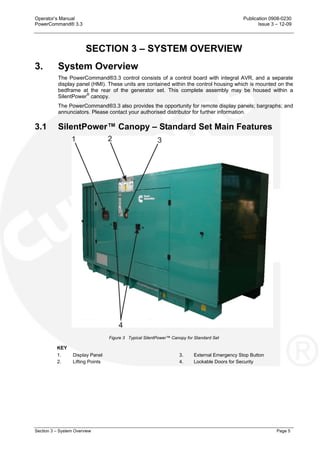
Page 20 Section 4 – Control System
Area 2 Active Fault or Screen Name
Area 2 displays the screen name and information about the last active shutdown fault. If there are
no active shutdown faults, it displays the last active warning fault.
If there is an active fault, the Operator Panel displays the following information about it:
• Fault type
• Event/fault code
• Name of the controller that detected the fault e.g. the engine ECM unit. This is blank if the
controller detected the fault
• Fault name.
If you press the Reset button the Operator Panel stops displaying active warning faults, even if the
condition(s) that caused the fault(s) has not been corrected. The Warning LED remains on,
however.
The Operator Panel always displays any active shutdown faults, even if the Reset button is
pressed.
FAULT TYPE DESCRIPTION
Warning This is a warning fault. (See Section 7 – Troubleshooting)
Derate This is a derate fault. (See Section 7 – Troubleshooting)
Shutdown This is a shutdown fault that initiates a Shutdown Without Cooldown
sequence. (See Section 7 – Troubleshooting)
Shutdown with Cooldown This is a shutdown fault that initiates a Shutdown With Cooldown sequence.
Area 3 Interactive Screen or Menu
Area 3 shows information relevant to Area 2. You can view the operating values for the generator
set, navigate through screens and adjust parameters (if permitted).
The default screen is the Genset Data screen.
The following table explains how the Operator Panel displays when the value of a specific
parameter is missing, unexpected, or outside the range allowed for the parameter.
OPERATOR PANEL DESCRIPTION
NWF Network Failure. There is a PCCNet network failure or a CAN (ECM) failure.
NWF of ECM values will occur just after the engine stops. This is normal
since the ECM keyswitch will not maintain the CAN datalink when the engine
is stopped.
OORL Out of Range Low.
The value is less that the lowest allowed value for this parameter.
OORH Out of Range High.
The value is greater that the highest allowed value for this parameter.
-- -- -- This value is not applicable.
Area 4 Additional Functions Indicators
Area 4 indicates the availability of other menus, additional information, and if further sub-menus
are available (indicated by up or down arrows [▲ and ▼]). If that particular page or menu has no
additional information, then no arrow will be visible at this time.
For example if the graphical display is not big enough to display the screen at one time an up
and/or down arrow (▲ and ▼) will be visible. Press the appropriate selection button beneath the
graphical display to look at the previous or next page of information in that screen.](https://image.slidesharecdn.com/pcc3-150827083627-lva1-app6891/85/Pcc-3-3-33-320.jpg)


![Publication 0908-0230 Operator’s Manual
Issue 3 – 12-09 PowerCommand® 3.3
Page 24 Section 4 – Control System
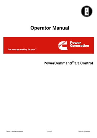
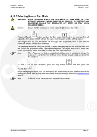
4.4 Display Module – Genset Data Operator Menu
Figure 12 shows a block representation of a typical Genset Data menu. To navigate from the
Home menu (HOME [1/2]), press the soft-key button below the function button indicating Genset.
This will take you directly to the Genset menu.
The Genset Data menu is displayed on two pages. Use the two soft-key buttons below the up and
down arrows (▲ and ▼) to toggle between the pages.
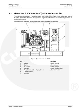
4.4.1 Generator Data
Use this menu to look at the status of the generator set.
NAME DESCRIPTION
Alternator
Avg Voltage Genset Line-to-Line average voltage.
Avg Current Genset average current.
Total kW Genset total kW.
Total PF Genset power factor.
Frequency Genset frequency.
Engine
Engine Hrs Total engine run time.
Coolant Temp Monitor point for the Coolant Temperature.
Oil Pressure Monitor point for the Oil Pressure.
Allowed values: 0~993 kPA (0~145 psi).
Batt Voltage Battery voltage value.
% Torq/Duty Monitor point for the percent engine torque output and the governor
percent duty cycle output when used with the HM ECM.
Allowed values: -125~125%.
Fuel Rate Monitor point for Fuel Rate.
Allowed values: 0~3199 L/hr (0~845 gal/hr).
Fuel Cons. Fuel consumption since last reset.
Total Fuel C. Total fuel consumption since start of engine.
Genset Application Rating
kW rating The genset kW rating.
kVA Rating The genset kVA Rating.
Rated Current The value of the genset application nominal current.
Genset Standby Rating
kW rating kW rating for the genset in Standby configuration.
kVA Rating kVA rating for the genset in Standby configuration.
Rated Current The value of the genset Standby nominal current.](https://image.slidesharecdn.com/pcc3-150827083627-lva1-app6891/85/Pcc-3-3-37-320.jpg)

![Publication 0908-0230 Operator’s Manual
Issue 3 – 12-09 PowerCommand® 3.3
Page 26 Section 4 – Control System
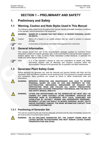
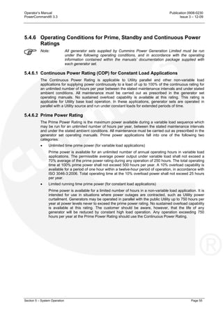
4.5 Display Module – Alternator Data Operator Menu
Figure 13 shows a block representation of a typical Alternator Data menu. To navigate from the
Home menu (HOME [1/2]), press the soft-key button below the function button indicating
Alternator. This will take you directly to the Alternator menu.
The Alternator Data menu is displayed on one page.
4.5.1 Alternator Data
Use this menu to look at the status of the alternator. This menu displays line-to-line voltage, line-
to-neutral voltage, current, and generator set power (in kVA). Some values are not available,
dependent on the number of phases (one or three) and whether or not the application has current
transformers.
NAME DESCRIPTION
L1
L2
L3
Alternator terminals.
LL(Vac) Genset L1L2 voltage.
Genset L2L3 voltage.
Genset L3L1 voltage.
LN(Vac) Genset L1N voltage.
Genset L2N voltage.
Genset L3N voltage.
Amps Monitors the current value:
Genset L1
Genset L2
Genset L3
kW Genset L1 kW.
Genset L2 kW.
Genset L3 kW.
kVA Genset L1 kVA.
Genset L2 kVA.
Genset L3 kVA.
PF* Genset L1 power factor.
Genset L2 power factor.
Genset L3 power factor.
Total kW Genset total kW.
Total kVA Genset total kVA.
Total PF* Genset power factor.
Frequency Genset frequency.
AVR Duty Cycle The AVR PWM software command. Linear relationship between counts
and % duty cycle with 10000 counts = 100% duty cycle.
* A negative (-) value indicates a leading power factor; a positive (+) value indicates a lagging power factor.](https://image.slidesharecdn.com/pcc3-150827083627-lva1-app6891/85/Pcc-3-3-39-320.jpg)

![Publication 0908-0230 Operator’s Manual
Issue 3 – 12-09 PowerCommand® 3.3
Page 28 Section 4 – Control System
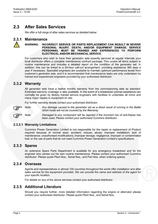
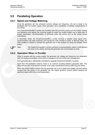
4.6 Display Module – Engine Data Operator Menu
Figure 14 shows a block representation of a typical Engine Data menu. To navigate from the
Home menu (HOME [1/2]), press the soft-key button below the function button indicating Engine.
This will take you directly to the Engine menu.
The Engine Data menu is displayed on one page.
4.6.1 Engine Data
Use this menu to look at the status of the engine.
NAME DESCRIPTION
Pressure
Oil Monitor point for the Oil Pressure.
Allowed values: 0~993 kPA (0~145 psi)
Boost Monitor point for the Boost Absolute Pressure.
Allowed values: 0~1014 kPA (0~148 psi)
Fuel Rail Monitor point for the Fuel Outlet Pressure.
Allowed values: 0~249364 kPA (0~36404 psi)
Fuel Inlet Monitor point for the Fuel Supply Pressure.
Allowed values: 0~993 kPA (0~145 psi)
Coolant Monitor point for the Coolant Pressure.
Allowed values: 0~993 kPA (0~145 psi)
Crankcase Monitor point for the Crankcase Pressure.
Allowed values: -244~260 kPA (-35.67~38 psi)
Ambient Monitor point for the Barometric Absolute Pressure.
Allowed values: 0~253 kPA (0~37 psi)
Temperature
Coolant Monitor point for the Coolant Temperature.
Oil Monitor point for the Oil Temperature.
Allowed values: -40~210
o
C (-40~410
o
F)
Manifold Monitor point for the Intake Manifold Temperature
Allowed values: -40~210
o
C (-40~410
o
F)
Fuel Inlet Monitor point for the Fuel Temperature.
Allowed values: -40~210
o
C (-40~410
o
F)
Aftercooler Monitor point for the Aftercooler Temperature.
Allowed values: -40~210
o
C (-40~410
o
F)
Engine Hrs Total engine run time.
Engine Speed Monitor point for the Average Engine Speed.
Batt Voltage Battery voltage value.](https://image.slidesharecdn.com/pcc3-150827083627-lva1-app6891/85/Pcc-3-3-41-320.jpg)


![Publication 0908-0230 Operator’s Manual
Issue 3 – 12-09 PowerCommand® 3.3
Page 38 Section 4 – Control System
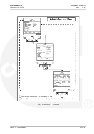
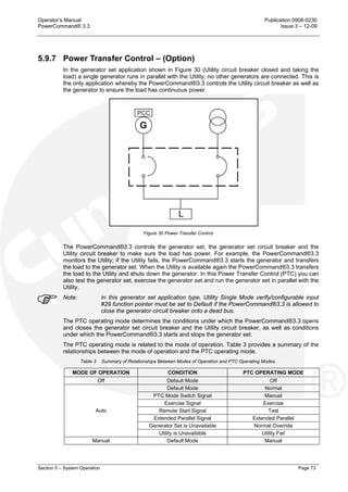
4.8 Display Module - Adjust Menu
Figure 19 shows a block representation of a typical Adjust menu. To navigate from the Home
menu (HOME [1/2]), press the soft-key button below the down arrow in the display window. This
will show the second page of the Home menu (HOME [2/2]). With the Adjust line of text
highlighted, press the O.K. button to display the information.
The Adjust menu is displayed on one page.
Note: Should any of these settings require amendment or change, please contact your
authorised service centre.
Note: You cannot adjust Frequency Adjust or Voltage Adjust if Paralleling Speed Control
Mode is set to Synchronise, Load Share, or Load Govern.
NAME DESCRIPTION
Voltage Adjust
Genset LL Average Voltage Genset Line to Line average voltage.
Voltage Adjust A trim that allows the user to add/subtract an offset to the nominal voltage
when calculating the voltage setpoint.
Allowed values: -5~5%. Default value: 0%
Rated/Idle Sw Allowed values: Rated, Idle. Default value: Rated.
Exer Switch Allowed values: Inactive, Active. Default value: Inactive.
Man Warm Byp Allowed values: Normal, Bypass Warmup.
Keyswitch
Keyswitch Status Allowed values: Inactive, Active.
Frequency Adjust
Final Frequency Reference The frequency scaled version of the final speed reference.
Allowed values: 0~100Hz.
Frequency Adjust A method of adding in a frequency offset to the base frequency subject to
high and low limit calibrations.
Allowed values: -6~6Hz. Default value: 0Hz.
Avr Gain A trim that allows the user to modify the overall gains of the AVR.
Allowed values: 0.05~10. Default value: 1
Governor Gain A trim that allows the user to modify the overall gain of the governor.
Allowed values: 0.05~10. Default value: 1
Start Delay Allowed values: 0~300 seconds. Default value: 0 seconds.
Stop Delay Allowed values: 0~600 seconds. Default value: 0 seconds.](https://image.slidesharecdn.com/pcc3-150827083627-lva1-app6891/85/Pcc-3-3-51-320.jpg)
![Publication 0908-0230 Operator’s Manual
Issue 3 – 12-09 PowerCommand® 3.3
Page 40 Section 4 – Control System
4.9 Display Module – Genset Setup Data Operator Menu
Figure 20 shows block representations of the Genset Setup Data menu.
Page down to the second page of the Home menu (using the two soft-key buttons below the up
and down arrows [▲ and ▼]). See Section 4.3.
In the HOME (2/2) menu, using the up and down arrows, toggle down again
until the Genset Setup text is highlighted.
With the Genset Setup line of text highlighted, press the OK button. This will
display the Setup Menu.
Use the two soft-key buttons below the up and down arrows [▲ and ▼]) to page through the five
pages of the generator Setup data.
Note: Should any of these settings require amendment or change, please contact your
authorised service centre.](https://image.slidesharecdn.com/pcc3-150827083627-lva1-app6891/85/Pcc-3-3-53-320.jpg)

![Publication 0908-0230 Operator’s Manual
Issue 3 – 12-09 PowerCommand® 3.3
Page 42 Section 4 – Control System
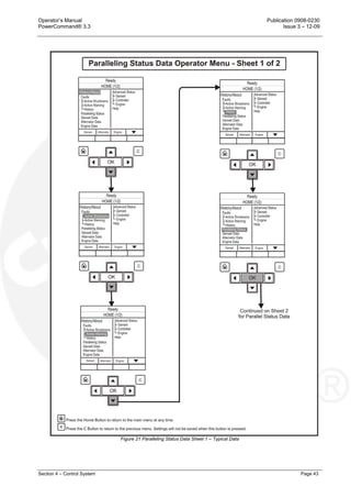
4.10 Display Module – Paralleling Status Menu
Figures 21 and 22 show block representations of a typical Paralleling Status menu.
In the HOME (1/2) menu, using the up and down arrows, toggle down until the
Paralleling Status text is highlighted.
With the Paralleling Status line of text highlighted, press the OK button. This
will display then display the Paralleling Status Menu.
Use the two soft-key buttons below the up and down arrows [▲ and ▼]) to page through the six
pages of the Paralleling Status menu.
Note: Should any of these settings require amendment or change, please contact your
authorised service centre.](https://image.slidesharecdn.com/pcc3-150827083627-lva1-app6891/85/Pcc-3-3-55-320.jpg)

![Operator’s Manual Publication 0908-0230
PowerCommand® 3.3 Issue 3 – 12-09
Section 4 – Control System Page 45
4.11 Display Module – Paralleling/Basic Setup Menu
Figures 23 and 24 show block representations of a typical Paralleling/Basic Setup menu.
To navigate from the HOME (1/2) menu, press the soft-key button below the
down arrow in the display window. This will show the second page of the
home menu (HOME 2/2). Using the up and down arrows, toggle down until the
Paralleling/Basic Setup text is highlighted.
With the Paralleling/Basic Setup line of text highlighted, press the OK button. This will then display
the Paralleling/Basic Setup Menu.
Note; It is also possible to short-cut to this menu by pressing the soft-key button below the
function button indicating Basic within the Paralleling Status menu.
Use the two soft-key buttons below the up and down arrows [▲ and ▼]) to page through the six
pages of the Paralleling/Basic Setup menu.
The adjustment of these submenus is intended for qualified service personnel and site personnel
only and may require a USER password for this operation. If a password is required the USER
password menu will appear when you try to modify the menu. (Refer to Password Menu in
Section 4.12).
Note: Should any of these settings require amendment or change, please contact your
authorised service centre.](https://image.slidesharecdn.com/pcc3-150827083627-lva1-app6891/85/Pcc-3-3-58-320.jpg)


![Operator’s Manual Publication 0908-0230
PowerCommand® 3.3 Issue 3 – 12-09
Section 5 – System Operation Page 57
5.5 Generator Set Operation
Correct care of your engine will result in longer life, better performance, and more economical
operation.
WARNING: DO NOT OPERATE A DIESEL ENGINE WHERE THERE ARE, OR CAN BE,
COMBUSTIBLE VAPOURS. THESE VAPOURS CAN BE SUCKED THROUGH
THE AIR INTAKE SYSTEM AND CAUSE ENGINE ACCELERATION AND
OVERSPEEDING, WHICH CAN RESULT IN A FIRE, AN EXPLOSION, AND
EXTENSIVE PROPERTY DAMAGE. NUMEROUS SAFETY DEVICES ARE
AVAILABLE, SUCH AS AIR INTAKE SHUTOFF DEVICES, TO MINIMIZE THE
RISK OF OVERSPEEDING IN WHICH AN ENGINE, BECAUSE OF
APPLICATION, MIGHT OPERATE IN A COMBUSTIBLE ENVIRONMENT (FROM
A FUEL SPILL OR GAS LEAK, FOR EXAMPLE). CUMMINS ENGINE COMPANY,
INC. DOES NOT KNOW HOW YOU WILL USE YOUR ENGINE. THE EQUIPMENT
OWNER AND OPERATOR, THEREFORE, IS RESPONSIBLE FOR SAFE
OPERATION IN A HOSTILE ENVIRONMENT. CONSULT YOUR CUMMINS
AUTHORISED DISTRIBUTOR FOR FURTHER INFORMATION.
Note: Cummins Power Generation Limited recommends the installation of an air intake
shutoff device or a similar safety device to minimise the risk of overspeeding where
an engine will be operated in a combustible environment.
Caution: Do not idle the engine for excessively long periods. Long periods of idling (more
than ten minutes) can damage an engine because combustion chamber
temperatures drop so low the fuel will not burn completely. This will cause carbon to
clog the injector spray holes and piston rings, and can cause the valves to stick. If
the engine coolant temperature becomes too low (60°C [140°F]), raw fuel will wash
the lubricating oil off the cylinder walls and dilute the crankcase oil. This will result in
the moving parts of the engine not receiving the correct quality of lubrication.](https://image.slidesharecdn.com/pcc3-150827083627-lva1-app6891/85/Pcc-3-3-70-320.jpg)


![Operator’s Manual Publication 0908-0230
PowerCommand® 3.3 Issue 2 – 5-09
Section 6 – Maintenance Page 89
SECTION 6 – MAINTENANCE
6. Maintenance
All maintenance tasks must be assessed for health and safety risks, the preventative measures
identified must be actioned. Accompaniment is required for tasks where the presence of someone
else will add significantly to the safety of the task.
Read, understand and comply with all Caution and Warning notes in this section, those contained
within Section 1 - Preliminary and Safety, and those contained within the Health and Safety
Manual (0908-0110-00). Refer also to the Operator’s engine specific manual supplied as part of
the generator set documentation pack. This latter manual will contain further information regarding
the running and care of the generator set and also specific equipment instructions that may differ
from the standard generator set.
Ensure adequate lighting and staging (where required) are installed.
Caution: Maintenance. must only be carry out by authorised and qualified maintenance
engineers, who are familiar with the equipment and its operation.
WARNING: DEPENDENT UPON THE CONTROL SYSTEM FITTED, THIS UNIT MAY
OPERATE AUTOMATICALLY AND COULD START WITHOUT WARNING.
Caution: Before carrying out any maintenance work, become familiar with the Generator
Plant Safety Code given in Section 1 of this manual, together with the Health and
Safety Manual (0908-0110-00).
Caution: Always disconnect a battery charger from its AC source before disconnecting the
battery leads. Failure to do so can result in voltage spikes high enough to damage
the DC control circuits of the generator set.
WARNING: ACCIDENTAL STARTING OF THE GENERATOR SET WHILE WORKING ON IT
CAN CAUSE SEVERE PERSONAL INJURY OR DEATH. PREVENT
ACCIDENTAL STARTING BY DISCONNECTING THE STARTING BATTERY
LEADS (NEGATIVE [-] FIRST).
ENSURE BATTERY AREA HAS BEEN WELL-VENTILATED BEFORE
SERVICING THE BATTERY. SPARKS OR ARCING CAN IGNITE EXPLOSIVE
HYDROGEN GAS GIVEN OFF BY BATTERIES, CAUSING SEVERE PERSONAL
INJURY. ARCING CAN OCCUR WHEN LEADS ARE REMOVED OR REPLACED,
OR WHEN THE NEGATIVE (-) BATTERY LEAD IS CONNECTED AND A TOOL
USED TO CONNECT OR DISCONNECT THE POSITIVE (+) BATTERY LEAD
TOUCHES THE FRAME OR OTHER GROUNDED METAL PART OF THE
GENERATOR SET.
INSULATED TOOLS MUST BE USED WHEN WORKING IN THE VICINITY OF
THE BATTERIES.
ALWAYS REMOVE THE NEGATIVE (-) LEAD FIRST AND RECONNECT LAST.
ENSURE HYDROGEN FROM THE BATTERY, ENGINE FUEL AND OTHER
EXPLOSIVE FUMES ARE FULLY DISSIPATED. THIS IS ESPECIALLY
IMPORTANT IF THE BATTERY HAS BEEN CONNECTED TO A BATTERY
CHARGER.
WARNING: TO COMPLETE MAINTENANCE TASKS AT HEIGHT REFER TO LOCAL
LEGISLATIVE REQUIREMENTS. SUITABLE EQUIPMENT FOR PERFORMING
THESE TASKS MUST BE USED IN ACCORDANCE WITH THE LOCAL
GUIDELINES AND LEGISLATION. FAILURE TO FOLLOW THESE
INSTRUCTIONS CAN RESULT IN SEVERE PERSONAL INJURY OR DEATH.](https://image.slidesharecdn.com/pcc3-150827083627-lva1-app6891/85/Pcc-3-3-102-320.jpg)


![Publication 0908-0230 Operator’s Manual
Issue 2 – 5-09 PowerCommand® 3.3
Page 102 Section 7 – Troubleshooting
7.3 Safety Considerations
Fault finding work, particularly in confined areas, must be carried out by two engineers working
together. Read, understand and comply with all safety precautions listed within Section 1 –
Preliminary and Safety – and observe all instructions and precautions throughout this manual, the
Operator’s engine specific manual, and the Health and Safety Manual (0908-0110).
The installation of a generator set can be designed for remote starting. When troubleshooting a
generator set that is shutdown ensure that the set cannot be accidentally re-started. Refer to
Section 6.2 – Locking the Generator Set out of Service.
WARNING: HIGH VOLTAGES ARE PRESENT WHEN THE GENERATOR SET IS RUNNING.
DO NOT OPEN THE OUTPUT BOX WHILE THE GENERATOR SET IS RUNNING.
WARNING: SOME PANEL INTERNAL COMPONENTS MAY HAVE LIVE EXPOSED
TERMINATIONS EVEN IF THE GENERATOR SET IS NOT RUNNING. ISOLATE
ALL EXTERNAL ELECTRICAL SUPPLIES PRIOR TO ACCESS OF THE
CONTROL PANEL.
WARNING: CONTACTING HIGH VOLTAGE COMPONENTS CAN CAUSE SEVERE
PERSONAL INJURY OR DEATH BY ELECTROCUTION. KEEP THE OUTPUT
BOX COVERS IN PLACE DURING TROUBLESHOOTING. TESTING AND/OR
ADJUSTMENTS MUST ONLY BE CARRIED OUT BY PERSONNEL QUALIFIED
TO PERFORM ELECTRICAL SERVICING.
Caution: Always disconnect a battery charger from its AC source before disconnecting the
battery leads. Failure to do so can result in voltage spikes high enough to damage
the DC control circuits of the generator set.
WARNING: VENTILATE BATTERY AREA BEFORE WORKING ON OR NEAR BATTERY –
WEAR GOGGLES – STOP GENERATOR SET AND DISCONNECT CHARGER
BEFORE DISCONNECTING BATTERY CABLES – DISCONNECT NEGATIVE(-)
CABLE FIRST AND RECONNECT LAST.
WARNING: IGNITION OF EXPLOSIVE BATTERY GASES CAN CAUSE SEVERE
PERSONAL INJURY OR DEATH. ARCING AT BATTERY TERMINALS, LIGHT
SWITCH OR OTHER EQUIPMENT, FLAME, PILOT LIGHTS AND SPARKS, CAN
IGNITE BATTERY GAS. DO NOT SMOKE, OR SWITCH INSPECTION LIGHT ON
OR OFF NEAR BATTERY. DISCHARGE STATIC ELECTRICITY FROM BODY
BEFORE TOUCHING BATTERIES BY FIRST TOUCHING A GROUNDED METAL
SURFACE.
WARNING: ACCIDENTAL STARTING OF THE GENERATOR SET WHILE WORKING ON IT
CAN CAUSE SEVERE PERSONAL INJURY OR DEATH. PREVENT
ACCIDENTAL STARTING BY DISCONNECTING THE STARTING BATTERY
LEADS (NEGATIVE [-] FIRST).](https://image.slidesharecdn.com/pcc3-150827083627-lva1-app6891/85/Pcc-3-3-114-320.jpg)


![Operator’s Manual Publication 0908-0230
PowerCommand® 3.3 Issue 2 – 5-09
Section 7 – Troubleshooting Page 105
7.6 Fault/Status Codes
WARNING: MANY TROUBLESHOOTING PROCEDURES PRESENT HAZARDS THAT CAN
RESULT IN SEVERE PERSONAL INJURY OR DEATH. SERVICE PROCEDURES
MUST ONLY BE CARRIED OUT BY QUALIFIED SERVICE PERSONNEL WITH
KNOWLEDGE OF FUELS, ELECTRICITY AND MACHINERY HAZARDS.
ACCIDENTAL STARTING OF THE GENERATOR SET WHILE WORKING ON IT
CAN CAUSE SEVERE PERSONAL INJURY OR DEATH. PREVENT
ACCIDENTAL STARTING BY DISCONNECTING THE STARTING BATTERY
LEADS (NEGATIVE [-] FIRST).
7.6.1 Fault Messages
A Fault message is an indicator of a Warning or Shutdown condition. It includes the fault type
(Warning or Shutdown), fault number, and a short description. It also includes where the fault
occurred if the generator set control did not detect the fault and is simply reporting the fault.
Table 5 provides a list of the fault codes, types, messages displayed, and descriptions of the
faults.
Active and acknowledged faults may be viewed in the Faults menu.
7.6.2 Fault Acknowledgement
Shutdown faults must be acknowledged after the fault has been corrected. If in Auto or Manual
mode, the control must be set to Stop mode (Off). Faults are cleared from the control panel display
by pressing the Reset button.
Faults are also acknowledged when in Auto mode and the remote start command is removed.
Faults are re-announced if they are detected again after being acknowledged.
Note: Gaps in the code numbers are for codes that do not apply to this generator set.
Some of the codes listed are feature dependent and will not be displayed by this
control.](https://image.slidesharecdn.com/pcc3-150827083627-lva1-app6891/85/Pcc-3-3-117-320.jpg)


This document is an operator's manual that provides guidance on safely operating and maintaining a PowerCommand 3.3 generator control system. It contains information on generator set components, control system operation, safety procedures, and contact information for support. The manual instructs operators to read both it and the accompanying engine-specific manual before operating the generator set. It also lists additional publications that may be relevant.