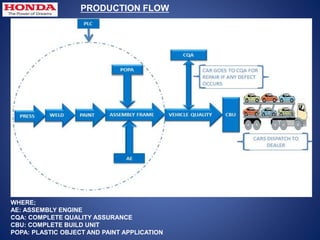
PRESNTATION ON SUMMER INTERNSHIP AT HONDA
CARS INDIA LIMITED
JAPAN BLOC
NORTH
AMERICA
BLOC
SOUTH
AMERIC
A BLOC
EUROPE-AFRICA-
MIDDLE EAST BLOC
ASIA/OCEANIA BLOC
Canada
USA
Ohio
Alabama
Mexico
Columbia
Brazil
Peru
Nigeria
UK
Morocco
Mauritius
Spain
France
Turkey
Italy
Australia
Indonesia
Malaysia
Thailand Philippines
Taiwan
China
India
Pakistan
Vietnam
1
2
3
5
6
4
HONDA worldwide operation
Cars
HONDA Jet
Power Products
• Leading Company in Mobility Business
• Product range from Motorcycles to Aircraft
• Future technologies - Robots, Fuel Cell Cars etc.
• Focus on Environment Friendly Technologies
Motorcycles
1949
1953
1963
2000
2004
Asimo
Fuel Cell Car
2008
HONDA history
PLANT-II
HCIL
CHENNAI
MUMBAI
Manufacturing Unit
Zonal Office
GR. NOIDA
PLANT -I
BHIWADI
HONDA MANMUFACTURING UNIT IN INDIA
Welcome to
Honda Cars India Ltd.
Tapukara (Rajasthan)
(Assembly Frame)
(Vehicle Quality)
(Plastic Object Painting Area)
(Assembly Engine)
COMPANY OVERVIEW
 5 S:
 5S is a method for achieving and sustaining efficiency and effectiveness
through organization and standardization in the workplace
 KAIZEN :- "change for the best"
 When applied to the workplace, kaizen refers to activities that
continually improve all functions, and involves all employees
from the CEO to the assembly line workers.
Press Shop
POPA (Plastic Object
Paint Application)
Al
Fe
Mission
Weld Shop
AE (Engine Assembly)
AF (Frame Assembly)
Vehicle Quality
PRODUCTION FLOW
WHERE;
AE: ASSEMBLY ENGINE
CQA: COMPLETE QUALITY ASSURANCE
CBU: COMPLETE BUILD UNIT
POPA: PLASTIC OBJECT AND PAINT APPLICATION
The Blank sheets of metal are received from RPSC. These Blank sheets of metal have a
thickness between 0.65 to 0.70 mm. There are two lines for the production of stamped
parts. The whole production process is automatic and is carried out with the help of robots.
A View Of Press Shop
 Press Shop
Stamping die used in forming of sheet
metal
 The Al department is responsible for development of all the aluminum parts,
for example the engine block and the engine head. CNC lathes and machining
tools like grinding wheels etc. are used.
Petrol Engine Block Manufactured in AL Shop
AL Shop
 Connecting rod and crank shaft are manufactured in FE Shop.
 There are two different production lines for con rod and crankshaft
Connecting Rod Crankshaft
 FE Shop
 The missions are made for two types of engines, diesel and petrol, with each
gear box having its own identification. The diesel model can be identified by
the presence of a single line on the main shaft while the petrol gear box has
two lines on the main shaft.
 Mission- A Subassembly Of Gear arrangement in gear
box
 MISSION SHOP
 PAINT SHOP
Paint Application
The main objectives of the Paint Division are to provide
vehicles with a high gloss, attractive, colorful finish, with a
long term durable resistance to corrosion.
PAINT INSPECTION
 AF SHOP (FRAME ASSEMBLY)
 Frame assembly is the last part of the production line.
 Parts from various shops are received,assembed dand
Finished cars drive out of the AF shop.
ASSEMBLY FRAME
MY WORK AREA: AE SHOP (ENGINE ASSEMBLY
Assembly
procedure
Assembly :-
Assembly is whole unit of subassembly
Subassembly :-
Subassembly is part of assembly
Sub assembly
Assembly
Assembly
●Combination number of parts
or subassemblies put together
to perform a specific function,
and capable of disassembly
without destruction.
What may be an assembly at
one point, however, may be a
subassembly at another.
Sub-Assembly
A unit assembled separately
but designed to fit with other
units in a manufactured
product
Example :
Piston sub assembly
PISTON SUBASSEMBLY
ASSEMBLED ENGINE
O
 Block Line:- This is the First Line in which the Cylinder
Block Loading , Piston Insertion , Crankshaft Installation ,
Flywheel Installation , Starter Motor Installation ,
Cylinder Head Docking etc. are take place. It consists of
Station No. 1 - 21 .
 Bare Line :-This is the Second Line in which the Rocker
Arm Installation, Fuel Pipe Installation , Connecting Pipe
Installation , Cam Chain Installation , Spark Plug
Installation , Mission Docking , etc. take place . It
Consists Of Station No. 22-42
 OHC Line :- This is the Last Line in which the Alternate
Current Generator Installation, AC Compressor, HAC
Belt, etc are take place . It consists of Station No. 43-53
LAYOUT OF ASSEMBLY LINE OF ENGINE
 Conveyors used
 Pallet
 Side out trolley
 Manipulator
 MBC Tightening machine
 Sealant application machine
 Pnuematic tools-For fastening purpose
 Torque wrench
 Sensors
 Couplers
 Wire harnesses
Belt type
 Conveyor belts are used in a wide variety of material
transport applications such as manufacturing, food
processing, and heavy industry.
 This conveyor is used in block and bare line
Overhead Conveyor
An overhead conveyor is an elevated system similar to a floor-level
conveyor belt that is used to transport items throughout a facility. Unlike a
conveyor belt, which is belt-driven, an overhead conveyor is driven by a
chain and is considerably thinner.
 Pallet is used to load the engine & carrying from one work
station to other station for assembly.
Jig Locating
pins (4 nos) of
palletPrimary (base)pallet
CYLINDER BLOCK PLACED ON A PALLET
Jigs
Pallet :
Cylinder block
 Side out trolley is used for taking out ‘Engine with pallet’ from conveyor in case
any problem with engine or any specific work to be done
 Since the main objective of a sealant is to seal assemblies and
joints, sealants need to have sufficient adhesion to the
substrates and resistance to environmental conditions to
remain bonded over the required life of the assembly.
Basic Requirement
・Provide mechanism to ensure the balance during component lift.
・Parts Weight 100Kg
・Revolution Angle 300 Degree (Attach adjustable
function)
・Revolution diameter 1500mm~2000mm
・Low & high range
・Installation Height 2000mm
・Provide mechanism to easily install the jig, attachment etc.
 Manipulator is used for picking the component from one specified place & place
at specified place
Mission coupling Subframe fitment
Manipulator for Mission coupling
 Accuracy ± 15%
 Torque setting Possible
 Operator dependency Less
 Torque transmission through oil pulse
(piston mechanism)
Application: Tightening bolt by pressing press button
Pulse unit
Trim
valve
Shut-off system
Air motor
Air
supply
in
Press
button
Socket for bolt
PNEUMATIC AIR GUN
Clicker torque wrenches signal when the desired
amount of torque is reached by emitting an
audible click
A tool for setting and adjusting the tightness of nuts and bolts to a desired value.
a) Clicker Torque Wrench
c) Open Torque Wrench
b) Dial Torque Wrench
Open torque wrench are also clicker type ,it has
open arrangement for holding Nut or bolt
A dial torque wrench is typically used as a
quality control instrument to verify or
monitor torque. The dial torque wrench can
be used for joint testing, auditing or
verification of torque applied.
Torque wrench
Socket
Bolt for tightening
MBC bolt tightening Cylinder head bolt tightening
OXYGEN SENSOR:
IT IS INSTALLED ABOVE THE CATALYTIC CONVERTOR AND USED
TO VERIFY THE BREATHING OF THE ENGINE. IT DETERMINE
WHETHER THE FUEL IS RICH OR LEAN. THEN SEND SIGNAL TO
E.C.U WHICH CONTROLS THE FUEL AIR MIXTURE ACCORDINGLY.
SENSORS
OXYGEN SENSOR
MAP SENSOR:
MAP STANDS FOR MANIFOLD ABSOLUTE PRESSURE AND
SENSOR IS USED TO PROVIDE THE INFORMATION OF MANIFOLD
PRESSURE TO E.C.U, WHICH IS NECESSARY TO CALCULATE AIR
DENSITY AND TO DETERMINE AIR MASS FLOW RATE, WHICH IN
TURN USED TO CALCULATE APPROPRIATE FUEL FLOW.
MAP SENSOR
FUNCTION OF PART:
 ENGINE COOLANT TEMPERATURE SENSOR:
THIS SENSOR IS INSTALLED ON THE REAR SIDE
OF CYLINDER HEAD AND IS USED TO SEND
TEMPERATURE INFORMATION TO E.C.U BY
DETERMINE THE COOLANT TEMPERATURE OF
AN ENGINE.
 TP SENSOR:
TP STANDS FOR THROTTLE POSITION AND SENSOR IS USED TO
DETERMINE THE THROTTLE VALVE POSITION. THE SIGNAL IS
USED BY E.C.U. AS IGNITIION TIMING AND FUEL INJECTION
TIMING DEPENDS UPON THE POSITION OF THE THROTTLE VALVE.
THROTTLE POSITION
SENSOR
ENGINE COOLANT TEMPERATURE
SENSOR
Coupler: Coupler mean connecting device & will handle multiple.
Terminal B is designed to prevent dislocation, & will not allow disconnection even it is
pulled
Coupler -B
Coupler- A
Multipoint
Handling of couplers
1. Couplers should be inserted fully
2. When disconnecting couplers, always
remove locks.
3. Couplers with lock should be checked to see
that locks are completely fixed
4. Insure the couplers are covered completely
5. Always grasp the main body of couplers
Terminals are used for connecting electrical circuits and male, female parts in pair
Terminals are used at place where fitting & removal can be easily accomplished
-connection by terminals are bonding of conductors & cause contact resistance
Terminal A
Terminal B
Handling of connectors
1. Do not use wire harness that are worn
2. Before connecting confirm that the connector cover
is not torn & female terminal is not open wide.
3. Insure the cover of terminal
4. Wire harness should be arranged so that ,there are
no slack& tension
Terminals
1.Cleanliness (Before
assembly)
The part that is going to
assemble must be clean,
free from dust, dent ,burr
&damage on its surface.
Example: Sealant application
area.
2.Lubrication (while assembly)
Some parts requires oil application during assembly,
it works as prilubrication.
Example: Piston ring assembly.
-while fitment of metal &journals engine oil must be
applied
SPRAY CLEANING CLEANING WITH CLOTH
LUBRICATION
3.Freeness (After assembly)
After fitment assembly to be checked
for freeness(no jam rotation)
Example: Crankshaft rotation, piston
ring rotation
4.Assembly confirmation (After
assembly)
After application of torque, assembly must
be identified by paint colour,on its bolt
CRANK ROTATION
CHECK
PROCESS
CONFIRMATION
5.Torque application :
-While giving torque ,hold the
torque wrench,as shown in
picture.
Socket point above the bolt
should be hold by left hand
Corner of the torque wrench
should be hold by right hand
Clik Sound: as the specified set
torque value reaches, auditable
click sound with feel will come ,
means torque is applied
-Do not over tight ,after click
sound
Patri ppt2

Patri ppt2

  • 1.
    PRESNTATION ON SUMMERINTERNSHIP AT HONDA CARS INDIA LIMITED
  • 2.
    JAPAN BLOC NORTH AMERICA BLOC SOUTH AMERIC A BLOC EUROPE-AFRICA- MIDDLEEAST BLOC ASIA/OCEANIA BLOC Canada USA Ohio Alabama Mexico Columbia Brazil Peru Nigeria UK Morocco Mauritius Spain France Turkey Italy Australia Indonesia Malaysia Thailand Philippines Taiwan China India Pakistan Vietnam 1 2 3 5 6 4 HONDA worldwide operation
  • 3.
    Cars HONDA Jet Power Products •Leading Company in Mobility Business • Product range from Motorcycles to Aircraft • Future technologies - Robots, Fuel Cell Cars etc. • Focus on Environment Friendly Technologies Motorcycles 1949 1953 1963 2000 2004 Asimo Fuel Cell Car 2008 HONDA history
  • 4.
    PLANT-II HCIL CHENNAI MUMBAI Manufacturing Unit Zonal Office GR.NOIDA PLANT -I BHIWADI HONDA MANMUFACTURING UNIT IN INDIA
  • 5.
    Welcome to Honda CarsIndia Ltd. Tapukara (Rajasthan)
  • 6.
    (Assembly Frame) (Vehicle Quality) (PlasticObject Painting Area) (Assembly Engine) COMPANY OVERVIEW
  • 7.
     5 S: 5S is a method for achieving and sustaining efficiency and effectiveness through organization and standardization in the workplace
  • 8.
     KAIZEN :-"change for the best"  When applied to the workplace, kaizen refers to activities that continually improve all functions, and involves all employees from the CEO to the assembly line workers.
  • 9.
    Press Shop POPA (PlasticObject Paint Application) Al Fe Mission Weld Shop AE (Engine Assembly) AF (Frame Assembly) Vehicle Quality
  • 10.
    PRODUCTION FLOW WHERE; AE: ASSEMBLYENGINE CQA: COMPLETE QUALITY ASSURANCE CBU: COMPLETE BUILD UNIT POPA: PLASTIC OBJECT AND PAINT APPLICATION
  • 11.
    The Blank sheetsof metal are received from RPSC. These Blank sheets of metal have a thickness between 0.65 to 0.70 mm. There are two lines for the production of stamped parts. The whole production process is automatic and is carried out with the help of robots. A View Of Press Shop  Press Shop Stamping die used in forming of sheet metal
  • 12.
     The Aldepartment is responsible for development of all the aluminum parts, for example the engine block and the engine head. CNC lathes and machining tools like grinding wheels etc. are used. Petrol Engine Block Manufactured in AL Shop AL Shop
  • 13.
     Connecting rodand crank shaft are manufactured in FE Shop.  There are two different production lines for con rod and crankshaft Connecting Rod Crankshaft  FE Shop
  • 14.
     The missionsare made for two types of engines, diesel and petrol, with each gear box having its own identification. The diesel model can be identified by the presence of a single line on the main shaft while the petrol gear box has two lines on the main shaft.  Mission- A Subassembly Of Gear arrangement in gear box  MISSION SHOP
  • 15.
     PAINT SHOP PaintApplication The main objectives of the Paint Division are to provide vehicles with a high gloss, attractive, colorful finish, with a long term durable resistance to corrosion.
  • 16.
  • 17.
     AF SHOP(FRAME ASSEMBLY)  Frame assembly is the last part of the production line.  Parts from various shops are received,assembed dand Finished cars drive out of the AF shop.
  • 18.
  • 19.
    MY WORK AREA:AE SHOP (ENGINE ASSEMBLY
  • 20.
  • 21.
    Assembly :- Assembly iswhole unit of subassembly Subassembly :- Subassembly is part of assembly Sub assembly Assembly
  • 22.
    Assembly ●Combination number ofparts or subassemblies put together to perform a specific function, and capable of disassembly without destruction. What may be an assembly at one point, however, may be a subassembly at another. Sub-Assembly A unit assembled separately but designed to fit with other units in a manufactured product Example : Piston sub assembly PISTON SUBASSEMBLY ASSEMBLED ENGINE
  • 23.
  • 24.
     Block Line:-This is the First Line in which the Cylinder Block Loading , Piston Insertion , Crankshaft Installation , Flywheel Installation , Starter Motor Installation , Cylinder Head Docking etc. are take place. It consists of Station No. 1 - 21 .  Bare Line :-This is the Second Line in which the Rocker Arm Installation, Fuel Pipe Installation , Connecting Pipe Installation , Cam Chain Installation , Spark Plug Installation , Mission Docking , etc. take place . It Consists Of Station No. 22-42  OHC Line :- This is the Last Line in which the Alternate Current Generator Installation, AC Compressor, HAC Belt, etc are take place . It consists of Station No. 43-53
  • 25.
    LAYOUT OF ASSEMBLYLINE OF ENGINE
  • 26.
     Conveyors used Pallet  Side out trolley  Manipulator  MBC Tightening machine  Sealant application machine  Pnuematic tools-For fastening purpose  Torque wrench  Sensors  Couplers  Wire harnesses
  • 27.
    Belt type  Conveyorbelts are used in a wide variety of material transport applications such as manufacturing, food processing, and heavy industry.  This conveyor is used in block and bare line
  • 28.
    Overhead Conveyor An overheadconveyor is an elevated system similar to a floor-level conveyor belt that is used to transport items throughout a facility. Unlike a conveyor belt, which is belt-driven, an overhead conveyor is driven by a chain and is considerably thinner.
  • 30.
     Pallet isused to load the engine & carrying from one work station to other station for assembly. Jig Locating pins (4 nos) of palletPrimary (base)pallet
  • 31.
    CYLINDER BLOCK PLACEDON A PALLET Jigs Pallet : Cylinder block
  • 32.
     Side outtrolley is used for taking out ‘Engine with pallet’ from conveyor in case any problem with engine or any specific work to be done
  • 34.
     Since themain objective of a sealant is to seal assemblies and joints, sealants need to have sufficient adhesion to the substrates and resistance to environmental conditions to remain bonded over the required life of the assembly.
  • 35.
    Basic Requirement ・Provide mechanismto ensure the balance during component lift. ・Parts Weight 100Kg ・Revolution Angle 300 Degree (Attach adjustable function) ・Revolution diameter 1500mm~2000mm ・Low & high range ・Installation Height 2000mm ・Provide mechanism to easily install the jig, attachment etc.  Manipulator is used for picking the component from one specified place & place at specified place
  • 36.
    Mission coupling Subframefitment Manipulator for Mission coupling
  • 37.
     Accuracy ±15%  Torque setting Possible  Operator dependency Less  Torque transmission through oil pulse (piston mechanism) Application: Tightening bolt by pressing press button Pulse unit Trim valve Shut-off system Air motor Air supply in Press button Socket for bolt
  • 38.
  • 39.
    Clicker torque wrenchessignal when the desired amount of torque is reached by emitting an audible click A tool for setting and adjusting the tightness of nuts and bolts to a desired value. a) Clicker Torque Wrench c) Open Torque Wrench b) Dial Torque Wrench Open torque wrench are also clicker type ,it has open arrangement for holding Nut or bolt A dial torque wrench is typically used as a quality control instrument to verify or monitor torque. The dial torque wrench can be used for joint testing, auditing or verification of torque applied.
  • 40.
    Torque wrench Socket Bolt fortightening MBC bolt tightening Cylinder head bolt tightening
  • 41.
    OXYGEN SENSOR: IT ISINSTALLED ABOVE THE CATALYTIC CONVERTOR AND USED TO VERIFY THE BREATHING OF THE ENGINE. IT DETERMINE WHETHER THE FUEL IS RICH OR LEAN. THEN SEND SIGNAL TO E.C.U WHICH CONTROLS THE FUEL AIR MIXTURE ACCORDINGLY. SENSORS OXYGEN SENSOR MAP SENSOR: MAP STANDS FOR MANIFOLD ABSOLUTE PRESSURE AND SENSOR IS USED TO PROVIDE THE INFORMATION OF MANIFOLD PRESSURE TO E.C.U, WHICH IS NECESSARY TO CALCULATE AIR DENSITY AND TO DETERMINE AIR MASS FLOW RATE, WHICH IN TURN USED TO CALCULATE APPROPRIATE FUEL FLOW. MAP SENSOR FUNCTION OF PART:
  • 42.
     ENGINE COOLANTTEMPERATURE SENSOR: THIS SENSOR IS INSTALLED ON THE REAR SIDE OF CYLINDER HEAD AND IS USED TO SEND TEMPERATURE INFORMATION TO E.C.U BY DETERMINE THE COOLANT TEMPERATURE OF AN ENGINE.  TP SENSOR: TP STANDS FOR THROTTLE POSITION AND SENSOR IS USED TO DETERMINE THE THROTTLE VALVE POSITION. THE SIGNAL IS USED BY E.C.U. AS IGNITIION TIMING AND FUEL INJECTION TIMING DEPENDS UPON THE POSITION OF THE THROTTLE VALVE. THROTTLE POSITION SENSOR ENGINE COOLANT TEMPERATURE SENSOR
  • 43.
    Coupler: Coupler meanconnecting device & will handle multiple. Terminal B is designed to prevent dislocation, & will not allow disconnection even it is pulled Coupler -B Coupler- A Multipoint Handling of couplers 1. Couplers should be inserted fully 2. When disconnecting couplers, always remove locks. 3. Couplers with lock should be checked to see that locks are completely fixed 4. Insure the couplers are covered completely 5. Always grasp the main body of couplers
  • 44.
    Terminals are usedfor connecting electrical circuits and male, female parts in pair Terminals are used at place where fitting & removal can be easily accomplished -connection by terminals are bonding of conductors & cause contact resistance Terminal A Terminal B Handling of connectors 1. Do not use wire harness that are worn 2. Before connecting confirm that the connector cover is not torn & female terminal is not open wide. 3. Insure the cover of terminal 4. Wire harness should be arranged so that ,there are no slack& tension Terminals
  • 45.
    1.Cleanliness (Before assembly) The partthat is going to assemble must be clean, free from dust, dent ,burr &damage on its surface. Example: Sealant application area. 2.Lubrication (while assembly) Some parts requires oil application during assembly, it works as prilubrication. Example: Piston ring assembly. -while fitment of metal &journals engine oil must be applied SPRAY CLEANING CLEANING WITH CLOTH LUBRICATION
  • 46.
    3.Freeness (After assembly) Afterfitment assembly to be checked for freeness(no jam rotation) Example: Crankshaft rotation, piston ring rotation 4.Assembly confirmation (After assembly) After application of torque, assembly must be identified by paint colour,on its bolt CRANK ROTATION CHECK PROCESS CONFIRMATION
  • 47.
    5.Torque application : -Whilegiving torque ,hold the torque wrench,as shown in picture. Socket point above the bolt should be hold by left hand Corner of the torque wrench should be hold by right hand Clik Sound: as the specified set torque value reaches, auditable click sound with feel will come , means torque is applied -Do not over tight ,after click sound