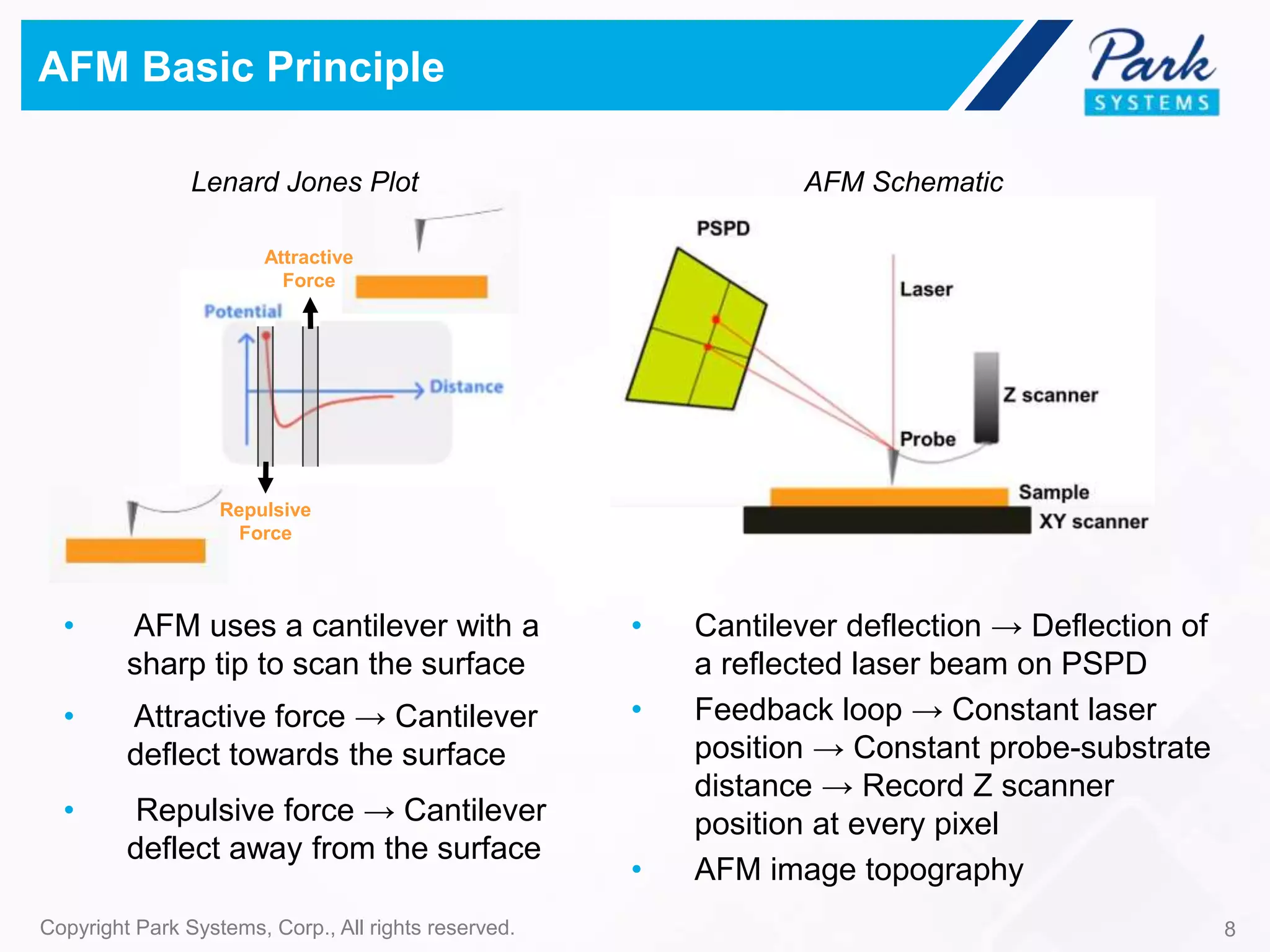
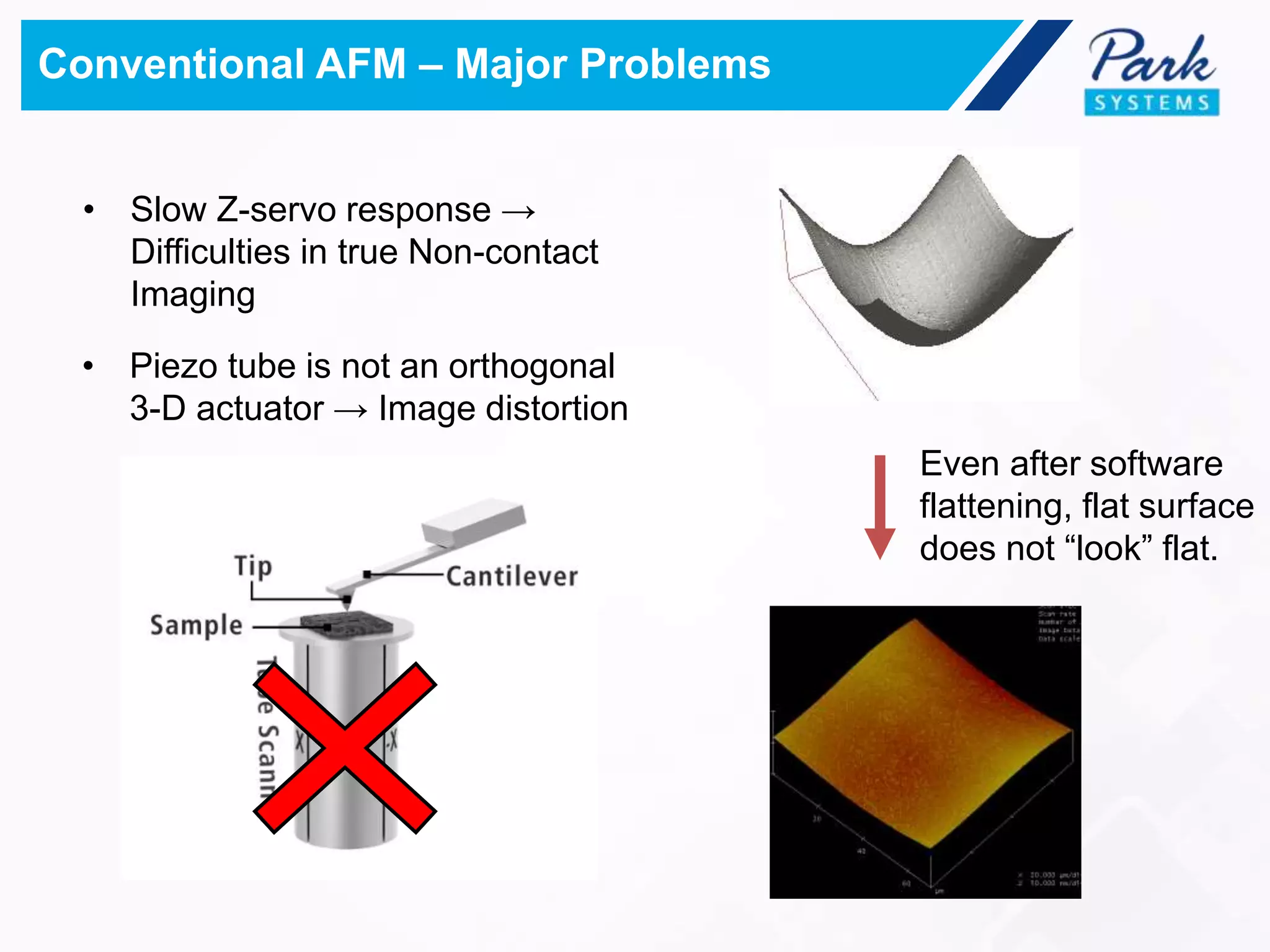
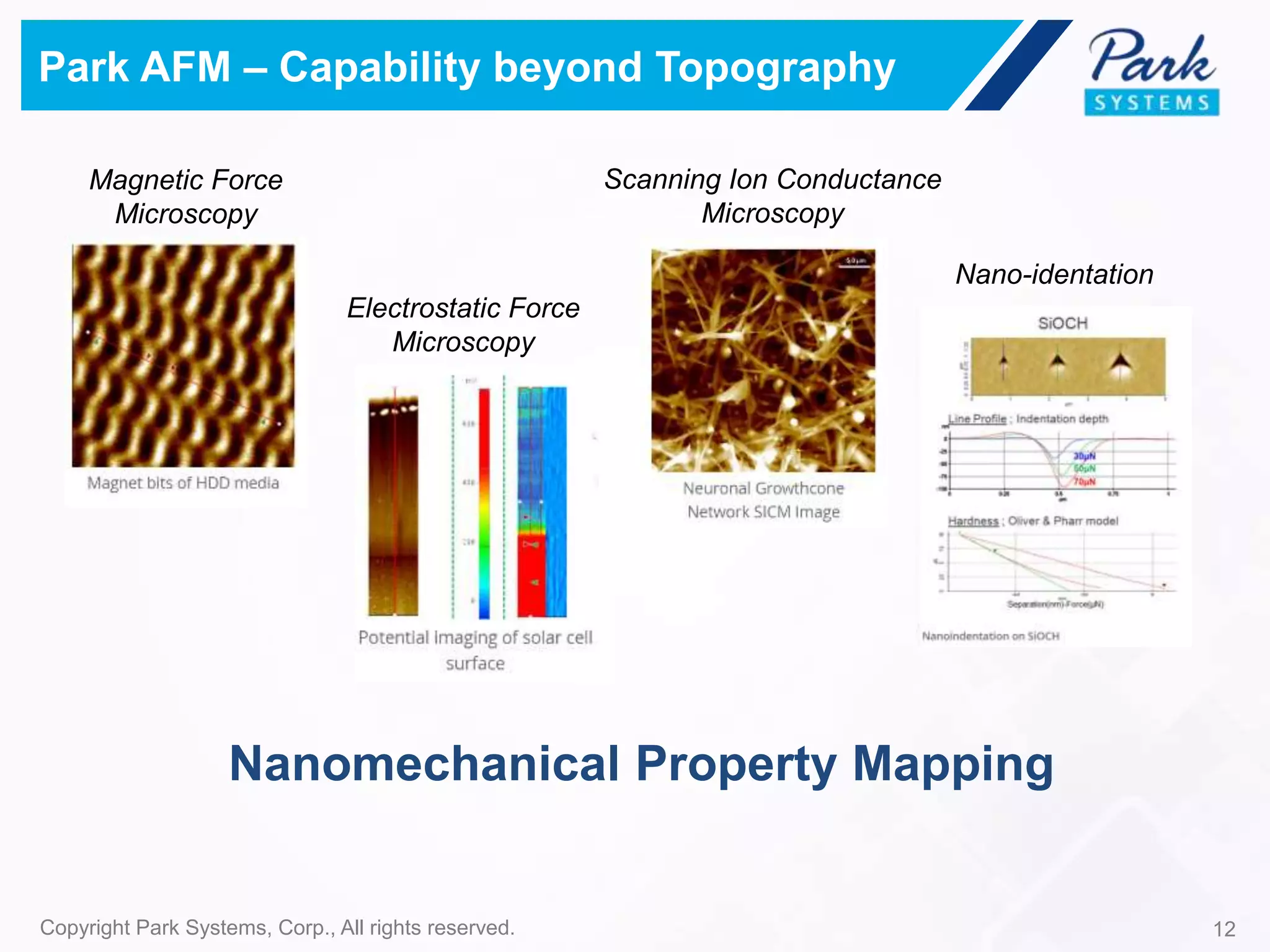
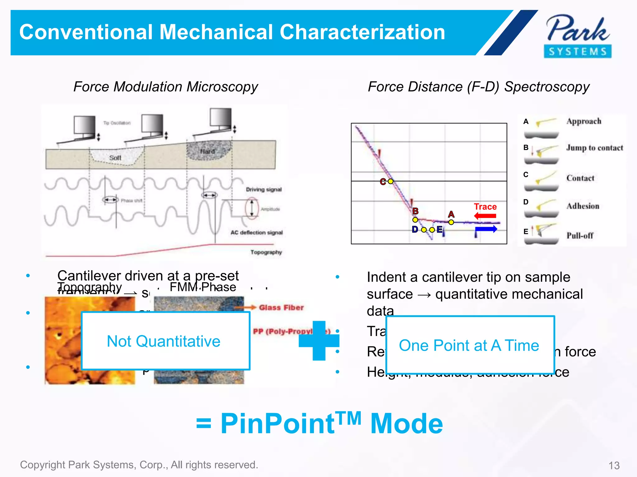
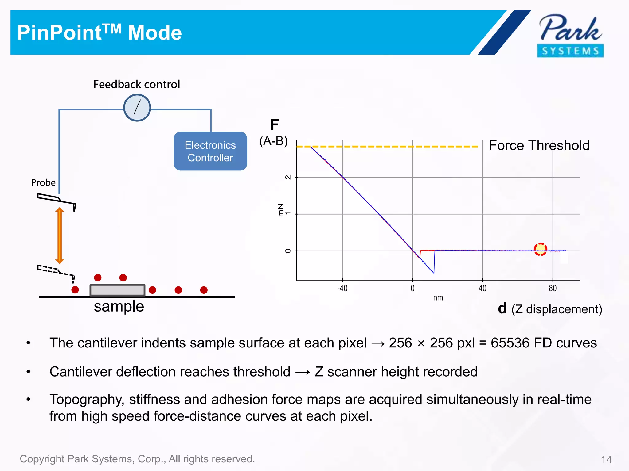
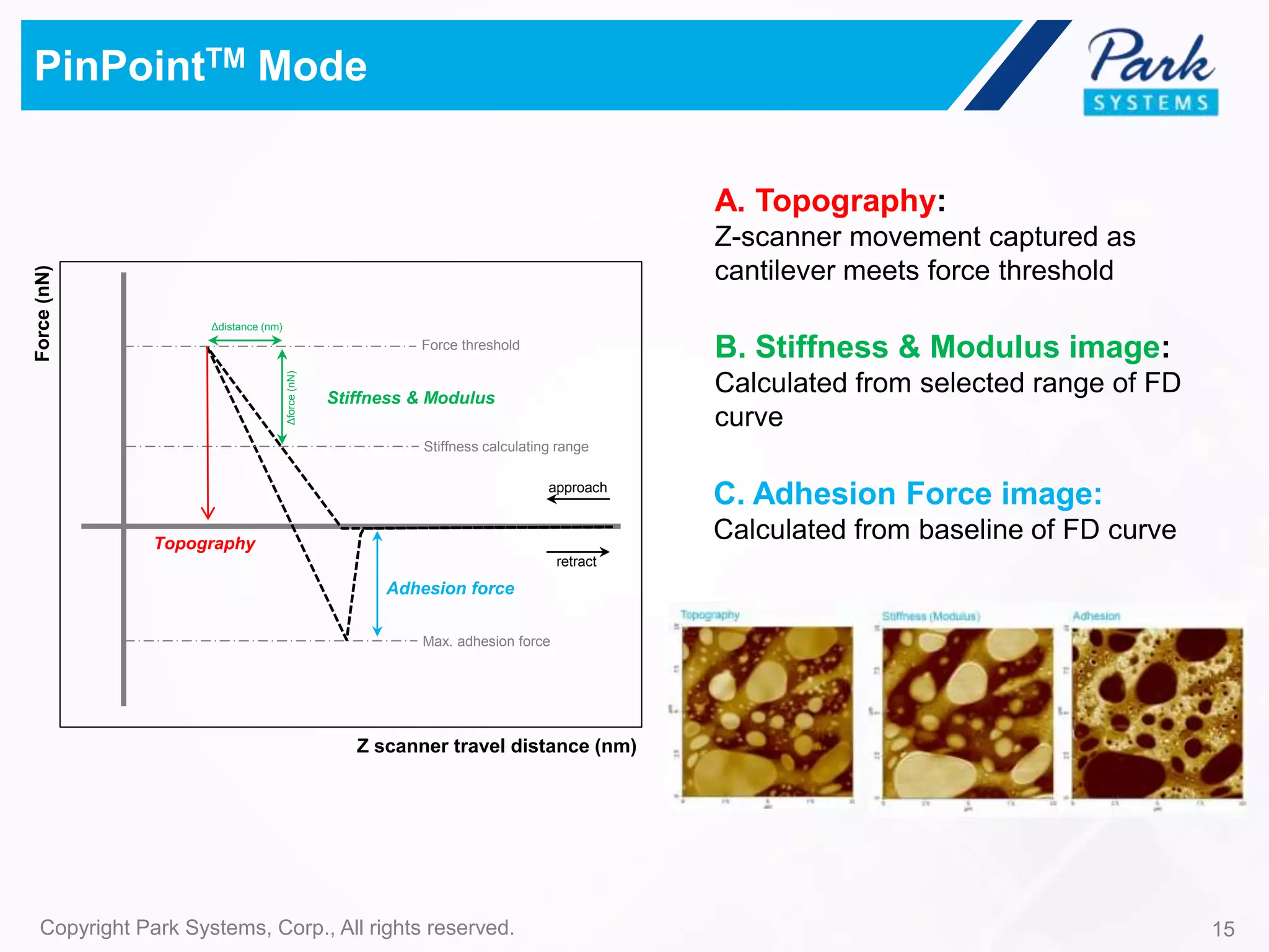
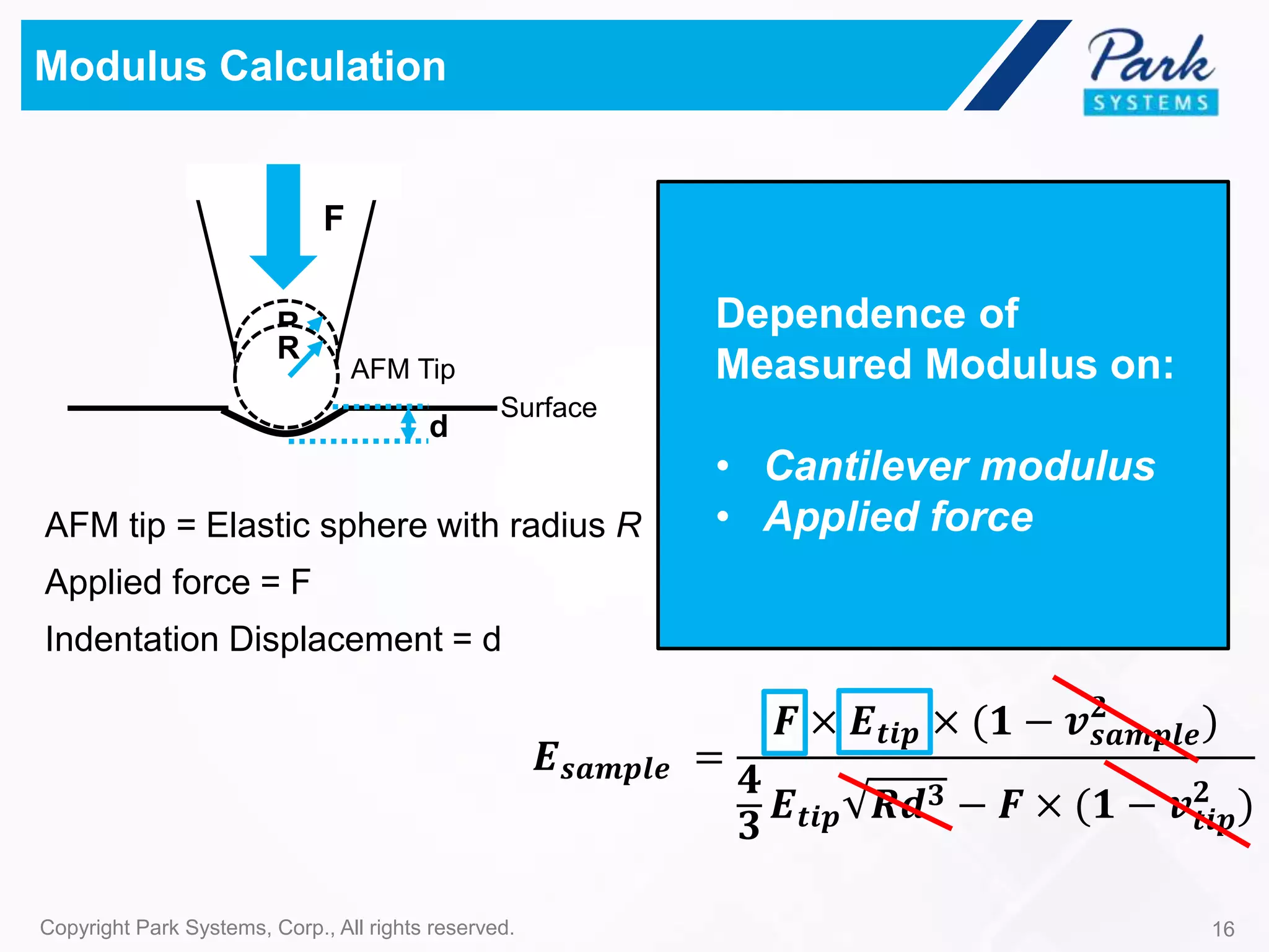
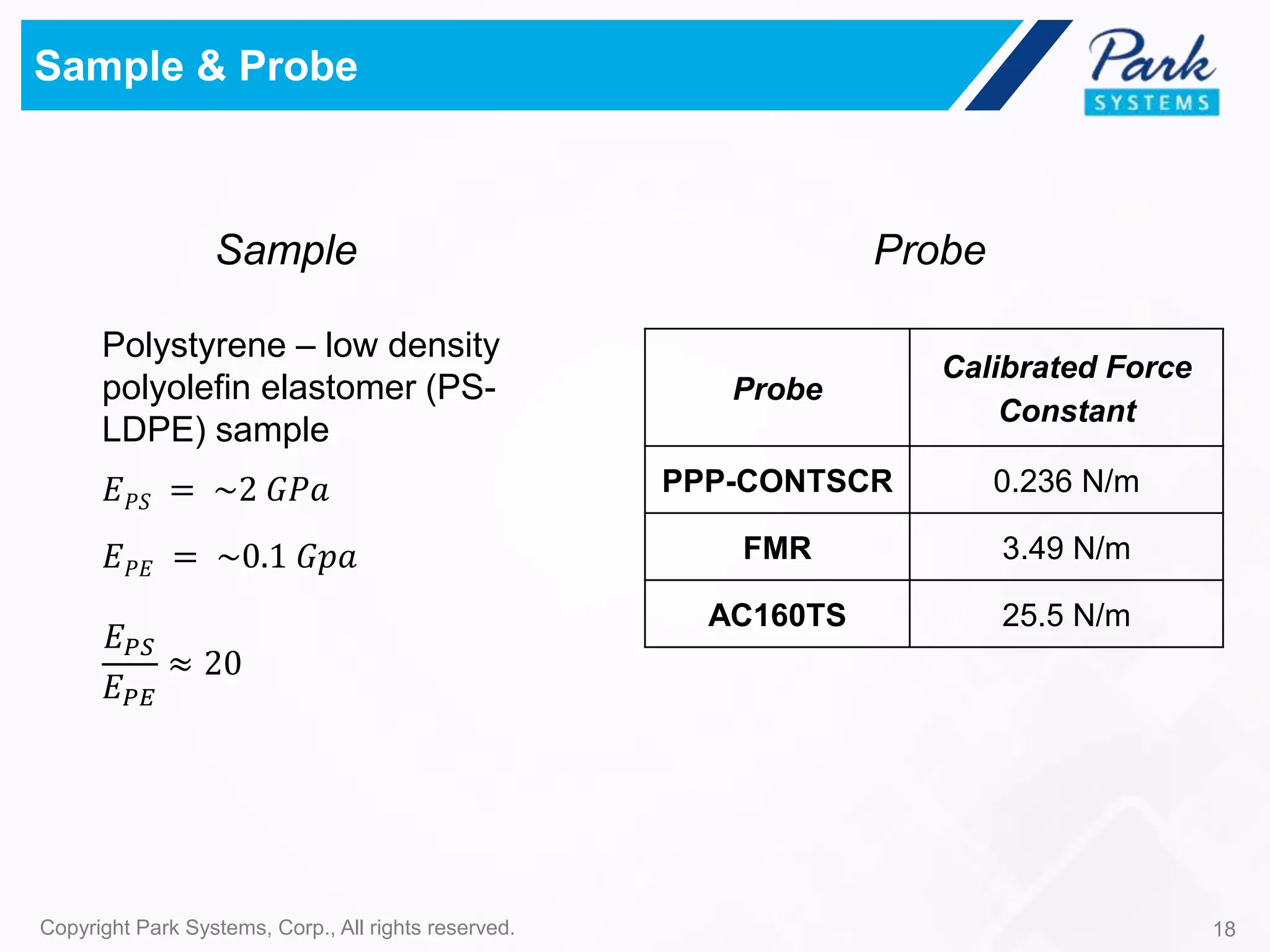
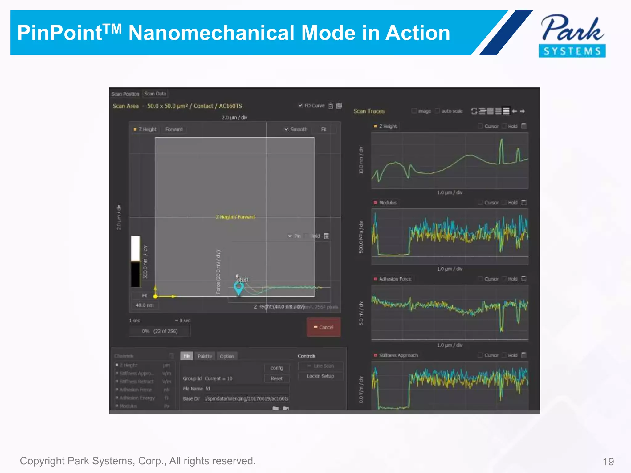
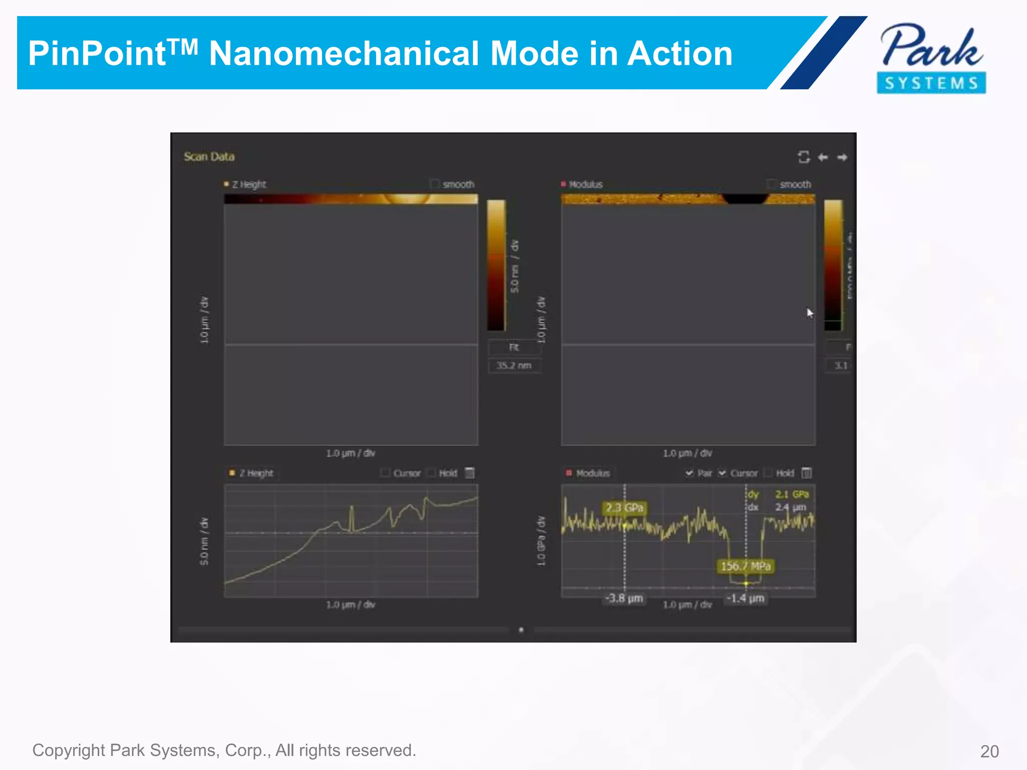
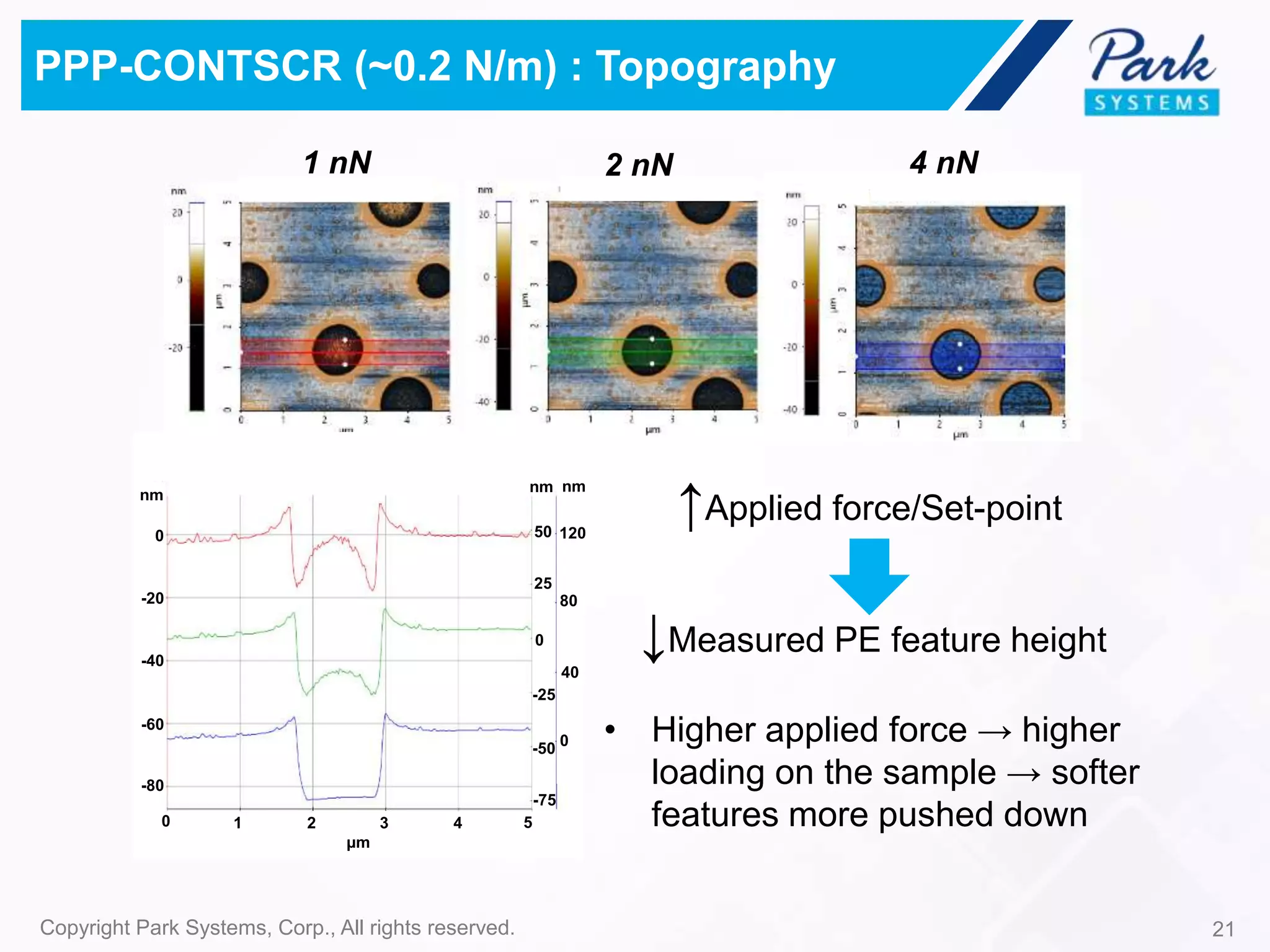
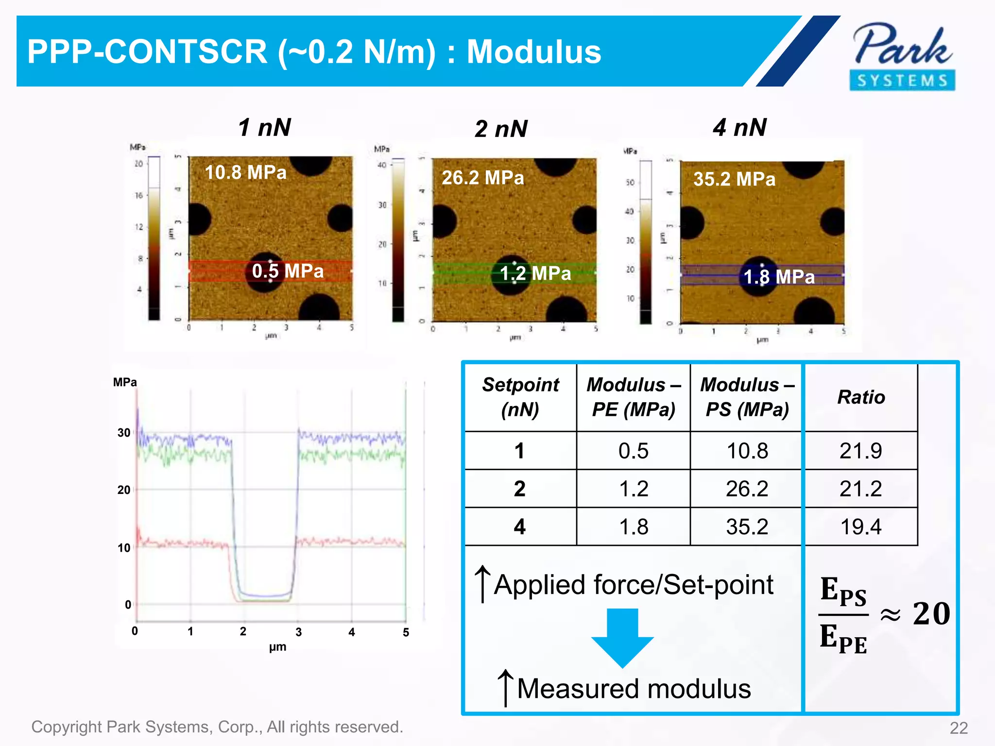
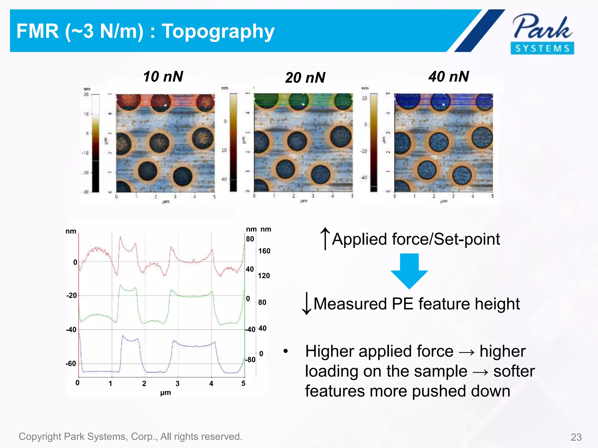
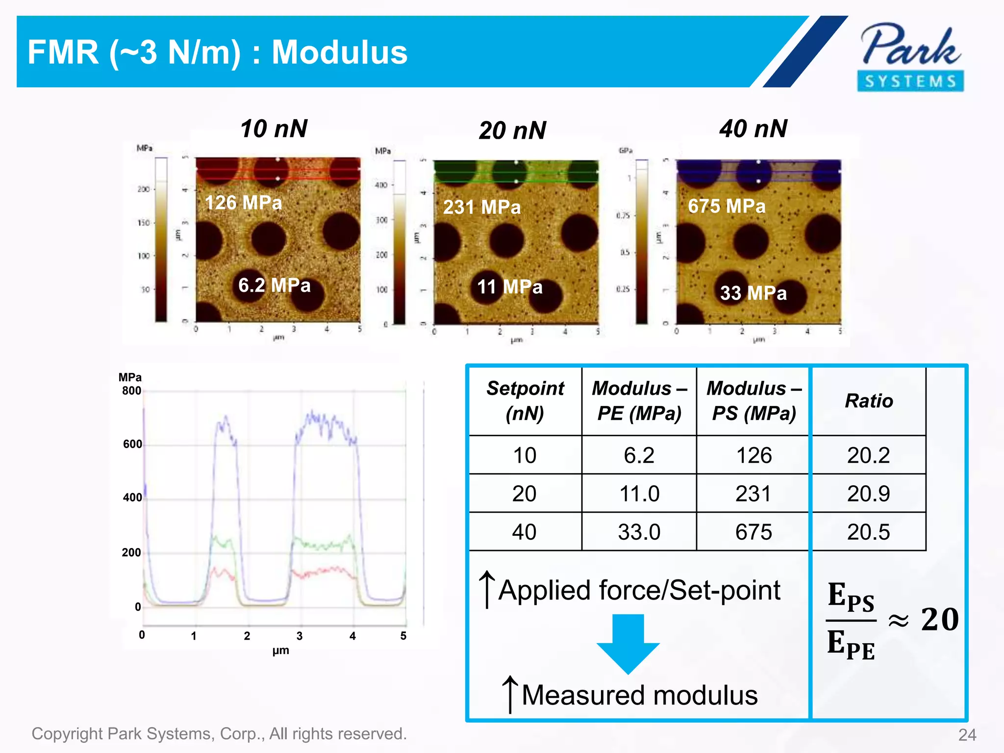
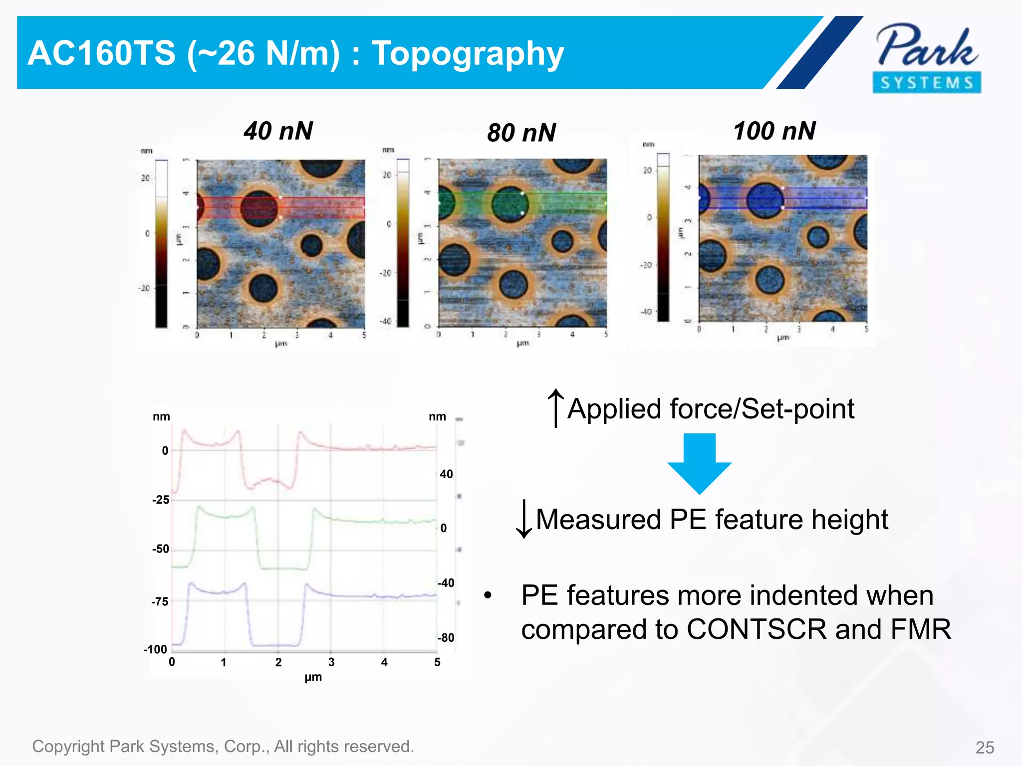
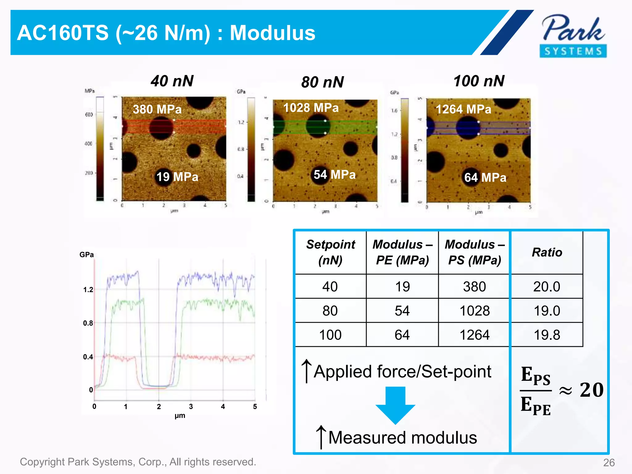
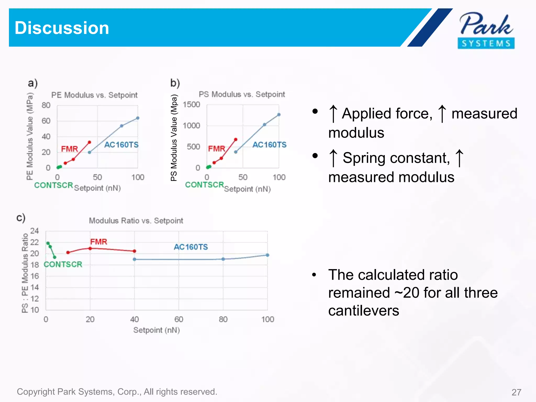
www.parkAFM.com
Atomic Force Microscopy PinPoint Nanomechanical
Mode for Nanoscale Modulus Mapping – Cantilever
Modulus and Applied Force
Park Systems, Inc.
July. 28, 2017
most major
Best Accuracy – Highest Resolution – Easiest to Use
5
Park AFM Scanner
Decoupled XY and Z Scanners
Park AFM Technology
True Non-Contact™ Mode
Park SmartScan™
Park AFM Operating Software
Learn more at www.PARKafm.com
6
• How AFM works
• Why PinPoint Nanomechanical mode
• PinPoint Nanomechanical mode
technique
• Influence of Probe Stiffness & Applied
Force on Measured Modulus
• CONTSCR
• FMR
• AC160TS
Outline
AFM Basic Principle
8Copyright Park Systems, Corp., All rights reserved.
• Attractive force → Cantilever
deflect towards the surface
Repulsive
Force
Attractive
Force
Lenard Jones Plot AFM Schematic
• AFM uses a cantilever with a
sharp tip to scan the surface
• Repulsive force → Cantilever
deflect away from the surface
• Cantilever deflection → Deflection of
a reflected laser beam on PSPD
• Feedback loop → Constant laser
position → Constant probe-substrate
distance → Record Z scanner
position at every pixel
• AFM image topography
• Slow Z-servo response →
Difficulties in true Non-contact
Imaging
Conventional AFM – Major Problems
• Piezo tube is not an orthogonal
3-D actuator → Image distortion
Even after software
flattening, flat surface
does not “look” flat.
Park Systems – AFM Technology Innovation
• Fast Z-servo → True Non-
Contact AFM imaging
• Flexure-based XY scanner →
high-precision nanometroloy
90.0°
70.0 µm
70.0 µm
Optical flat (80x80µm)
10 µm pitch calibration grating
< 1 nm
Single module parallel-kinematics
x-y scanner
15 μm
< 5 nm
0
Copyright Park Systems, Corp., All rights reserved. 11
Preload spring
Kinematic pin
Park Systems – AFM Technology Innovation
• Z scanner straightness → Z
scan out of motion < 0.015%
Park AFM – Capability beyond Topography
12Copyright Park Systems, Corp., All rights reserved.
Nanomechanical Property Mapping
Electrostatic Force
Microscopy
Magnetic Force
Microscopy
Scanning Ion Conductance
Microscopy
Nano-identation
13Copyright Park Systems, Corp., All rights reserved.
Conventional Mechanical Characterization
Force Modulation Microscopy
• Cantilever driven at a pre-set
frequency → set amplitude and phase
• Variation in sample mechanical
properties → change in amplitude and
phase
• Height, FMM phase, FMM amplitude
Topography FMM Phase
Not Quantitative
Force Distance (F-D) Spectroscopy
Trace
A
B
C
E
D
• Indent a cantilever tip on sample
surface → quantitative mechanical
data
• Trace → hardness/modulus
• Retrace → stickiness/adhesion force
• Height, modulus, adhesion force
One Point at A Time
= PinPointTM Mode
PinPointTM Mode
Probe
sample
Electronics
Controller
Feedback control
14Copyright Park Systems, Corp., All rights reserved.
(A-B)
d (Z displacement)
F
• The cantilever indents sample surface at each pixel → 256 × 256 pxl = 65536 FD curves
• Cantilever deflection reaches threshold → Z scanner height recorded
• Topography, stiffness and adhesion force maps are acquired simultaneously in real-time
from high speed force-distance curves at each pixel.
Force Threshold
PinPointTM Mode
15Copyright Park Systems, Corp., All rights reserved.
B. Stiffness & Modulus image:
Calculated from selected range of FD
curve
A. Topography:
Z-scanner movement captured as
cantilever meets force threshold
C. Adhesion Force image:
Calculated from baseline of FD curve
Force(nN)
Z scanner travel distance (nm)
approach
retract
Force threshold
Stiffness calculating range
Topography
Δdistance (nm)
Δforce(nN)
Stiffness & Modulus
Max. adhesion force
Adhesion force
AFM Tip
16Copyright Park Systems, Corp., All rights reserved.
Modulus Calculation
E*: Effective elastic modulus
Indentation Displacement = d
Surface
AFM tip = Elastic sphere with radius R
R
F
R
d
𝐅 =
𝟒
𝟑
𝐄∗ 𝐑𝐝 𝟑
𝟏
𝐄∗
=
𝟏 − 𝐯𝐭𝐢𝐩
𝟐
𝐄𝐭𝐢𝐩
+
𝟏 − 𝐯𝐬𝐚𝐦𝐩𝐥𝐞
𝟐
𝐄 𝐬𝐚𝐦𝐩𝐥𝐞
E*: Effective elastic modulus
v: Poisson’s ratio
𝑬 𝒔𝒂𝒎𝒑𝒍𝒆 =
𝑭 × 𝑬 𝒕𝒊𝒑 × (𝟏 − 𝒗 𝒔𝒂𝒎𝒑𝒍𝒆
𝟐
)
𝟒
𝟑
𝑬 𝒕𝒊𝒑 𝑹𝒅 𝟑 − 𝑭 × (𝟏 − 𝒗 𝒕𝒊𝒑
𝟐
)
Applied force = F
Dependence of
Measured Modulus on:
• Cantilever modulus
• Applied force
The Instrument
Park NX10 AFM
Park Systems (c) All rights reserved.
The Experiment
“The world’s most accurate AFM”
“The easiest to use atomic force
microscope”
18Copyright Park Systems, Corp., All rights reserved.
Sample & Probe
Probe
Calibrated Force
Constant
PPP-CONTSCR 0.236 N/m
FMR 3.49 N/m
AC160TS 25.5 N/m
Polystyrene – low density
polyolefin elastomer (PS-
LDPE) sample
𝐸 𝑃𝑆 = ~2 𝐺𝑃𝑎
𝐸 𝑃𝐸 = ~0.1 𝐺𝑝𝑎
𝐸 𝑃𝑆
𝐸 𝑃𝐸
≈ 20
Sample Probe
19Copyright Park Systems, Corp., All rights reserved.
PinPointTM Nanomechanical Mode in Action
20Copyright Park Systems, Corp., All rights reserved.
PinPointTM Nanomechanical Mode in Action
21Copyright Park Systems, Corp., All rights reserved.
PPP-CONTSCR (~0.2 N/m) : Topography
1 nN 2 nN 4 nN
↑Applied force/Set-point
↓Measured PE feature height
• Higher applied force → higher
loading on the sample → softer
features more pushed down
0
-20
-40
-60
-80
nm
120
80
40
0
nm
50
nm
25
0
-25
-50
-75
0 1 2 3 4 5
µm
30
20
10
0
MPa
0 1 2 3 4 5
µm
22Copyright Park Systems, Corp., All rights reserved.
PPP-CONTSCR (~0.2 N/m) : Modulus
1 nN 2 nN 4 nN
10.8 MPa
0.5 MPa 1.2 MPa
26.2 MPa 35.2 MPa
1.8 MPa
Setpoint
(nN)
Modulus –
PE (MPa)
Modulus –
PS (MPa)
Ratio
1 0.5 10.8 21.9
2 1.2 26.2 21.2
4 1.8 35.2 19.4
𝐄 𝐏𝐒
𝐄 𝐏𝐄
≈ 𝟐𝟎
↑Applied force/Set-point
↑Measured modulus
0 1 2 3 4 5
µm
0
-20
-40
-60
nm
40
0
-40
-80
nm
80
120
80
40
0
nm
160
23Copyright Park Systems, Corp., All rights reserved.
FMR (~3 N/m) : Topography
10 nN 20 nN 40 nN
↑Applied force/Set-point
↓Measured PE feature height
• Higher applied force → higher
loading on the sample → softer
features more pushed down
24Copyright Park Systems, Corp., All rights reserved.
FMR (~3 N/m) : Modulus
Setpoint
(nN)
Modulus –
PE (MPa)
Modulus –
PS (MPa)
Ratio
10 6.2 126 20.2
20 11.0 231 20.9
40 33.0 675 20.5
𝐄 𝐏𝐒
𝐄 𝐏𝐄
≈ 𝟐𝟎
↑Applied force/Set-point
↑Measured modulus
33 MPa
675 MPa231 MPa
11 MPa
126 MPa
6.2 MPa
10 nN 20 nN 40 nN
0 1 2 3 4 5
µm
800
600
400
0
200
MPa
25Copyright Park Systems, Corp., All rights reserved.
AC160TS (~26 N/m) : Topography
40 nN 80 nN 100 nN
↑Applied force/Set-point
↓Measured PE feature height
• PE features more indented when
compared to CONTSCR and FMR
0
-25
-50
-75
nm
-100
40
0
-40
-80
nm
0 1 2 3 4 5
µm
1264 MPa
64 MPa
1028 MPa
54 MPa
380 MPa
19 MPa
26Copyright Park Systems, Corp., All rights reserved.
AC160TS (~26 N/m) : Modulus
Setpoint
(nN)
Modulus –
PE (MPa)
Modulus –
PS (MPa)
Ratio
40 19 380 20.0
80 54 1028 19.0
100 64 1264 19.8
𝐄 𝐏𝐒
𝐄 𝐏𝐄
≈ 𝟐𝟎
↑Applied force/Set-point
↑Measured modulus
40 nN 80 nN 100 nN
1.2
0.8
0.4
0
GPa
0 1 2 3 4 5
µm
27Copyright Park Systems, Corp., All rights reserved.
Discussion
• ↑ Applied force, ↑ measured
modulus
• ↑ Spring constant, ↑
measured modulus
• The calculated ratio
remained ~20 for all three
cantilevers
PSModulusValue(Mpa)
Summary
• Measured modulus values increase with applied force
and cantilever force constant.
• To obtain precise modulus values, a cantilever with
proper force constant need to be selected.
• Park PinPointTM mode can accurately measure relative
sample modulus ratio/difference within a sample.
Thank you!
29Copyright Park Systems, Corp., All rights reserved.

Park Systems Pin point presentation

  • 1.
    www.parkAFM.com Atomic Force MicroscopyPinPoint Nanomechanical Mode for Nanoscale Modulus Mapping – Cantilever Modulus and Applied Force Park Systems, Inc. July. 28, 2017
  • 3.
  • 5.
    Best Accuracy –Highest Resolution – Easiest to Use 5 Park AFM Scanner Decoupled XY and Z Scanners Park AFM Technology True Non-Contact™ Mode Park SmartScan™ Park AFM Operating Software
  • 6.
    Learn more atwww.PARKafm.com 6
  • 7.
    • How AFMworks • Why PinPoint Nanomechanical mode • PinPoint Nanomechanical mode technique • Influence of Probe Stiffness & Applied Force on Measured Modulus • CONTSCR • FMR • AC160TS Outline
  • 8.
    AFM Basic Principle 8CopyrightPark Systems, Corp., All rights reserved. • Attractive force → Cantilever deflect towards the surface Repulsive Force Attractive Force Lenard Jones Plot AFM Schematic • AFM uses a cantilever with a sharp tip to scan the surface • Repulsive force → Cantilever deflect away from the surface • Cantilever deflection → Deflection of a reflected laser beam on PSPD • Feedback loop → Constant laser position → Constant probe-substrate distance → Record Z scanner position at every pixel • AFM image topography
  • 9.
    • Slow Z-servoresponse → Difficulties in true Non-contact Imaging Conventional AFM – Major Problems • Piezo tube is not an orthogonal 3-D actuator → Image distortion Even after software flattening, flat surface does not “look” flat.
  • 10.
    Park Systems –AFM Technology Innovation • Fast Z-servo → True Non- Contact AFM imaging • Flexure-based XY scanner → high-precision nanometroloy 90.0° 70.0 µm 70.0 µm Optical flat (80x80µm) 10 µm pitch calibration grating < 1 nm Single module parallel-kinematics x-y scanner
  • 11.
    15 μm < 5nm 0 Copyright Park Systems, Corp., All rights reserved. 11 Preload spring Kinematic pin Park Systems – AFM Technology Innovation • Z scanner straightness → Z scan out of motion < 0.015%
  • 12.
    Park AFM –Capability beyond Topography 12Copyright Park Systems, Corp., All rights reserved. Nanomechanical Property Mapping Electrostatic Force Microscopy Magnetic Force Microscopy Scanning Ion Conductance Microscopy Nano-identation
  • 13.
    13Copyright Park Systems,Corp., All rights reserved. Conventional Mechanical Characterization Force Modulation Microscopy • Cantilever driven at a pre-set frequency → set amplitude and phase • Variation in sample mechanical properties → change in amplitude and phase • Height, FMM phase, FMM amplitude Topography FMM Phase Not Quantitative Force Distance (F-D) Spectroscopy Trace A B C E D • Indent a cantilever tip on sample surface → quantitative mechanical data • Trace → hardness/modulus • Retrace → stickiness/adhesion force • Height, modulus, adhesion force One Point at A Time = PinPointTM Mode
  • 14.
    PinPointTM Mode Probe sample Electronics Controller Feedback control 14CopyrightPark Systems, Corp., All rights reserved. (A-B) d (Z displacement) F • The cantilever indents sample surface at each pixel → 256 × 256 pxl = 65536 FD curves • Cantilever deflection reaches threshold → Z scanner height recorded • Topography, stiffness and adhesion force maps are acquired simultaneously in real-time from high speed force-distance curves at each pixel. Force Threshold
  • 15.
    PinPointTM Mode 15Copyright ParkSystems, Corp., All rights reserved. B. Stiffness & Modulus image: Calculated from selected range of FD curve A. Topography: Z-scanner movement captured as cantilever meets force threshold C. Adhesion Force image: Calculated from baseline of FD curve Force(nN) Z scanner travel distance (nm) approach retract Force threshold Stiffness calculating range Topography Δdistance (nm) Δforce(nN) Stiffness & Modulus Max. adhesion force Adhesion force
  • 16.
    AFM Tip 16Copyright ParkSystems, Corp., All rights reserved. Modulus Calculation E*: Effective elastic modulus Indentation Displacement = d Surface AFM tip = Elastic sphere with radius R R F R d 𝐅 = 𝟒 𝟑 𝐄∗ 𝐑𝐝 𝟑 𝟏 𝐄∗ = 𝟏 − 𝐯𝐭𝐢𝐩 𝟐 𝐄𝐭𝐢𝐩 + 𝟏 − 𝐯𝐬𝐚𝐦𝐩𝐥𝐞 𝟐 𝐄 𝐬𝐚𝐦𝐩𝐥𝐞 E*: Effective elastic modulus v: Poisson’s ratio 𝑬 𝒔𝒂𝒎𝒑𝒍𝒆 = 𝑭 × 𝑬 𝒕𝒊𝒑 × (𝟏 − 𝒗 𝒔𝒂𝒎𝒑𝒍𝒆 𝟐 ) 𝟒 𝟑 𝑬 𝒕𝒊𝒑 𝑹𝒅 𝟑 − 𝑭 × (𝟏 − 𝒗 𝒕𝒊𝒑 𝟐 ) Applied force = F Dependence of Measured Modulus on: • Cantilever modulus • Applied force
  • 17.
    The Instrument Park NX10AFM Park Systems (c) All rights reserved. The Experiment “The world’s most accurate AFM” “The easiest to use atomic force microscope”
  • 18.
    18Copyright Park Systems,Corp., All rights reserved. Sample & Probe Probe Calibrated Force Constant PPP-CONTSCR 0.236 N/m FMR 3.49 N/m AC160TS 25.5 N/m Polystyrene – low density polyolefin elastomer (PS- LDPE) sample 𝐸 𝑃𝑆 = ~2 𝐺𝑃𝑎 𝐸 𝑃𝐸 = ~0.1 𝐺𝑝𝑎 𝐸 𝑃𝑆 𝐸 𝑃𝐸 ≈ 20 Sample Probe
  • 19.
    19Copyright Park Systems,Corp., All rights reserved. PinPointTM Nanomechanical Mode in Action
  • 20.
    20Copyright Park Systems,Corp., All rights reserved. PinPointTM Nanomechanical Mode in Action
  • 21.
    21Copyright Park Systems,Corp., All rights reserved. PPP-CONTSCR (~0.2 N/m) : Topography 1 nN 2 nN 4 nN ↑Applied force/Set-point ↓Measured PE feature height • Higher applied force → higher loading on the sample → softer features more pushed down 0 -20 -40 -60 -80 nm 120 80 40 0 nm 50 nm 25 0 -25 -50 -75 0 1 2 3 4 5 µm
  • 22.
    30 20 10 0 MPa 0 1 23 4 5 µm 22Copyright Park Systems, Corp., All rights reserved. PPP-CONTSCR (~0.2 N/m) : Modulus 1 nN 2 nN 4 nN 10.8 MPa 0.5 MPa 1.2 MPa 26.2 MPa 35.2 MPa 1.8 MPa Setpoint (nN) Modulus – PE (MPa) Modulus – PS (MPa) Ratio 1 0.5 10.8 21.9 2 1.2 26.2 21.2 4 1.8 35.2 19.4 𝐄 𝐏𝐒 𝐄 𝐏𝐄 ≈ 𝟐𝟎 ↑Applied force/Set-point ↑Measured modulus
  • 23.
    0 1 23 4 5 µm 0 -20 -40 -60 nm 40 0 -40 -80 nm 80 120 80 40 0 nm 160 23Copyright Park Systems, Corp., All rights reserved. FMR (~3 N/m) : Topography 10 nN 20 nN 40 nN ↑Applied force/Set-point ↓Measured PE feature height • Higher applied force → higher loading on the sample → softer features more pushed down
  • 24.
    24Copyright Park Systems,Corp., All rights reserved. FMR (~3 N/m) : Modulus Setpoint (nN) Modulus – PE (MPa) Modulus – PS (MPa) Ratio 10 6.2 126 20.2 20 11.0 231 20.9 40 33.0 675 20.5 𝐄 𝐏𝐒 𝐄 𝐏𝐄 ≈ 𝟐𝟎 ↑Applied force/Set-point ↑Measured modulus 33 MPa 675 MPa231 MPa 11 MPa 126 MPa 6.2 MPa 10 nN 20 nN 40 nN 0 1 2 3 4 5 µm 800 600 400 0 200 MPa
  • 25.
    25Copyright Park Systems,Corp., All rights reserved. AC160TS (~26 N/m) : Topography 40 nN 80 nN 100 nN ↑Applied force/Set-point ↓Measured PE feature height • PE features more indented when compared to CONTSCR and FMR 0 -25 -50 -75 nm -100 40 0 -40 -80 nm 0 1 2 3 4 5 µm
  • 26.
    1264 MPa 64 MPa 1028MPa 54 MPa 380 MPa 19 MPa 26Copyright Park Systems, Corp., All rights reserved. AC160TS (~26 N/m) : Modulus Setpoint (nN) Modulus – PE (MPa) Modulus – PS (MPa) Ratio 40 19 380 20.0 80 54 1028 19.0 100 64 1264 19.8 𝐄 𝐏𝐒 𝐄 𝐏𝐄 ≈ 𝟐𝟎 ↑Applied force/Set-point ↑Measured modulus 40 nN 80 nN 100 nN 1.2 0.8 0.4 0 GPa 0 1 2 3 4 5 µm
  • 27.
    27Copyright Park Systems,Corp., All rights reserved. Discussion • ↑ Applied force, ↑ measured modulus • ↑ Spring constant, ↑ measured modulus • The calculated ratio remained ~20 for all three cantilevers PSModulusValue(Mpa)
  • 28.
    Summary • Measured modulusvalues increase with applied force and cantilever force constant. • To obtain precise modulus values, a cantilever with proper force constant need to be selected. • Park PinPointTM mode can accurately measure relative sample modulus ratio/difference within a sample.
  • 29.
    Thank you! 29Copyright ParkSystems, Corp., All rights reserved.