SlideShare a Scribd company logo
1 of 108
Download to read offline
628
Everyone talks about the future, but Rittal helps shape it – and that includes
the field of climate control. Development work focuses on the holistic protec-
tion of process control with the minimum possible energy consumption.
Modern cooling units with favourable operating ratios and high tech
recooling systems open up brand new perspectives for energy-saving,
efficient cooling of electronic components and machines. This is crucial to the
availability and reliability of production systems and IT technology.
For this reason, Rittal collaborates closely with you to develop customised
climate control concepts.
R
629
Rittal Catalogue 32/System Climate Control
B
4.
System
Climate
Control
System Climate Control
Cooling units from page 630
Features.......................................................................................... 630
Modular climate control concept
Cooling module, useful cooling output 1500/2500 W..................... 633
Section doors for installing cooling modules.................................. 634
Climate control side panels ............................................................ 635
Roof-mounted cooling units
Useful cooling output 500/750 W ................................................... 636
Useful cooling output 1000 W ........................................................ 637
Useful cooling output 1100/3000 W ............................................... 638
Useful cooling output 1500/2000 W ............................................... 639
Useful cooling output 3000/4000 W ............................................... 640
With CO2 as the coolant, useful cooling output 1000 W................. 653
Wall-mounted cooling units
VIP small cooling units, useful cooling output 225 W..................... 641
Mini in horizontal format, useful cooling output 300 W................... 642
Useful cooling output 300/500 W ................................................... 643
Useful cooling output 750 W .......................................................... 644
Useful cooling output 1000/1500 W ............................................... 645
Slimline, useful cooling output 1500 W........................................... 646
Useful cooling output 2000/2500 W ............................................... 647
Useful cooling output 4000 W ........................................................ 648
Design NEMA 4x, useful cooling output 500/1000/1500 W............ 649
Design NEMA 4x, useful cooling output 2000/2500 W................... 650
For precision machine tools,
useful cooling output 1000/1500 W ................................................ 651
Zone 22 (dust) explosion-proof cooling units,
useful cooling output 1000/1500 W ................................................ 652
With CO2 as the coolant, useful cooling output 1000 W................. 653
Recooling systems from page 654
Features.......................................................................................... 654
Recooling systems
Mini ................................................................................................. 656
Mini, for wall mounting.................................................................... 659
In floor-standing enclosure............................................................. 660
In floor-standing enclosure for oil ................................................... 662
In TS 8 Top enclosure system ........................................................ 664
In industrial enclosure .................................................................... 666
Chiller for IT cooling........................................................................ 667
Immersible recooling systems for oil .............................................. 669
Immersible recooling systems for emulsion ................................... 672
Heat exchangers from page 684
Features.......................................................................................... 675
Air/water heat exchangers
Micro, wall-mounted ....................................................................... 676
Wall-mounted.................................................................................. 677
Roof-mounted ................................................................................. 682
Features.......................................................................................... 684
Water/water heat exchangers
In TS 8 Top enclosure system ........................................................ 685
Features.......................................................................................... 686
Air/air heat exchangers
Wall-mounted.................................................................................. 687
Fan-and-filter units from page 689
Features.......................................................................................... 689
Fan-and-filter units
Air throughput 20/55 m3/h – 550/700 m3/h ..................................... 690
Fan-and-filter units – EMC
Air throughput 20 – 700 m3/h.......................................................... 694
Climate control tailored to enclosures from page 696
Features.......................................................................................... 696
Rack-mounted cooling units for 482.6 mm (19″)......................... 698
Rack-mounted fans for 482.6 mm (19″) ....................................... 699
Centrifugal fans ............................................................................ 700
Fan systems .................................................................................. 701
Heaters from page 708
Features.......................................................................................... 708 Enclosure heaters
Continuous thermal output 10 – 300 W .......................................... 709
Accessories for System Climate Control from page 710
Features.......................................................................................... 710
Accessories for system climate control
Air routing ....................................................................................... 711
Control/regulation ........................................................................... 714
General ........................................................................................... 718
Filter technology for cooling units................................................... 723
Liquid cooling from page 726
Applications.................................................................................... 726
Rittal Liquid Cooling Package ..................................................... 727
Accessories for Rittal Liquid Cooling Package ......................... 729
Features.......................................................................................... 731
DCP – Direct Cooling Package .................................................... 732
630 Rittal Catalogue 32/System Climate Control
Cooling units
Features
B
4.1
Cooling
units
Intelligent control
The two controller variants for
operational reliability offer a
comprehensive range of func-
tions.
Essential control electronics are
well protected and cooled in the
inner circuit.
Both variants have the following
properties:
● Three voltage options:
115 V, 230 V, 400/460 V 3~
● Integral start-up delay and
door limit switch function
● Icing protection function
● Monitoring of all motors
● Phase monitoring for
three-phase units
Basic controller:
● Visualisation of the operating
status via LED display
● Switching hysteresis: 5 K
● Floating fault signal contact
in case of overtemperature
● Setpoint setting may be made
externally via potentiometer
Comfort controller:
● Switching hysteresis: 2 – 10 K
preset to 5 K
● System alarm, individually
configurable for 2 floating fault
signal contacts
● Visualisation of the current
enclosure internal tempera-
ture and all system messages
on the display
● Storage of all system states in
the log file
● Optional extension card for
integration into superordinate
remote monitoring systems
e. g. with CMC
Rittal System Climate Control offers holistic process protec-
tion. This includes the cooling of sensitive electronics in
enclosures and cases for industrial process control, as well
as server and network technology, regardless of the respec-
tive ambient conditions. But these are not isolated solutions –
with Rittal, everything is interconnected. Perfectly linked
and controlled cooling technology with eco-friendly, energy-
efficient equipment.
Selection criteria
Modular climate control door
concept
The unity of enclosure and
cooling components achieves
particularly effective cooling.
Assembly time is eliminated.
The investment costs for the
complete unit offer exception-
ally good value for money.
Roof-mounted cooling units
Requirement-oriented routing of
cooling air in the internal circuit
is possible, with up to four cold
air outlet openings and the op-
tional use of ducts. In the exter-
nal circuit, the heated air is ex-
pelled to the rear, left and right,
and optionally upwards. This
facilitates bayed installation,
and siting close to the wall.
Wall-mounted cooling units
Depending on the space and
design requirements, internal
mounting, partial internal mount-
ing and external mounting are all
possible. Thanks to large dis-
tances between the air intake
and outlet openings, effective
cold air throughput of the enclo-
sure is achieved.
Benefits:
● Useful cooling output from
225 W to 4000 W
● Extensive control and moni-
toring features, even with the
basic version
● Three-phase cooling units
support multiple voltages as
standard
● Uniform, output-related, cross-
system mounting cut-outs, to
match TopTherm air/air and
air/water heat exchangers
● Targeted, individual air
routing
● No assembly work and low
investment costs, thanks to
the complete solution con-
sisting of an enclosure and
integral cooling unit1)
● May be integrated directly
into TS 8 bayed enclosure
suites1)
Important:
● Use a base/plinth of at least
100 mm height to ensure
uninhibited air entry1)
● Avoid overloading the roof
plate by using stays (see
TS 8 system accessories)
● Air inlet and outlet openings
in the internal and external
circuit must not be
obstructed.
1) Only for modular climate
control door concept.
Cooling units
Features
631
Rittal Catalogue 32/System Climate Control
B
4.1
Cooling
units
Flexible output
Only 3 mounting cut-outs for
6 different output categories.
Targeted air routing in the
enclosure
The heated air is centrally ex-
tracted. Targeted air occurs via
optional channels in the four
corners, depending on require-
ments.
Electronic condensate evapo-
ration as standard
Condensate is effectively evapo-
rated.
Energy-efficient and resource-conserving
For those who place their trust in
Rittal, value-added comes as
standard. What is more, Rittal is
a global trendsetter in the field of
climate control.
A host of pioneering concepts
bear witness to this fact: Rittal
TopTherm cooling units are
equipped as standard with
innovative RiNano-coating and
integral electronic conden-
sate evaporation.
Roof-mounted cooling units
Wall-mounted cooling units
Wall-mounted cooling units –
practical and stylish
Whether external, internal or par-
tial internal mounting,
optimum use is made of the
available space.
Effective air routing inside the
enclosure
Thanks to the large distance
between air inlet and outlet in
the internal circuit, optimum
through-flow of the enclosure
is ensured, thereby avoiding air
short-circuits.
Electronic condensate evapo-
ration as standard
Condensate is effectively evapo-
rated.
Cooling units for special applications
Wall-mounted cooling units
for machine tools with high
acceleration rates and in-
creased sensitivity to vibration.
Explosion-proof wall-mounted
cooing units for Zone 22 (dust).
Roof-mounted cooling units –
specifically for office applica-
tions with a considerably lower
noise level.
632 Rittal Catalogue 32/System Climate Control
Modular climate control concept
Features
B
4.1
Modular
climate
control
concept
1
2
600
1800/2000
800
1800/2000
1200
1800/2000
1200
1800/2000
3
4
6
5
Less is more! With only six cooling modules and eight door
modules, we are now able to provide you with a virtually infi-
nite variety of applications. The best cooling technology,
complete and ready for use – without having to make mount-
ing cut-outs. The existing sheet steel doors can simply be
changed for the section doors with the cooling modules.
These can also be exchanged or upgraded during operation.
Your benefits:
● Modular design – for individ-
ual size, cooling power and
voltage combinations
● Simple, fast mounting
● Service-friendly (front rack-
mounted filter and remova-
ble cover)
● Quick delivery
Our concept:
● TS 8 section door and cli-
mate control combination
● One item number each for
the door and climate control
module
● 8 section doors x 6 climate
control modules = 48 combi-
nation options
● Standard RTT PLUS version
with integral condensate
evaporation and RiNano-
coating
Infinite possibilities
Seamless baying and perfect
integration. The TS base/plinth
is required for operation.
Comfort controller
Optimum function and control
monitoring.
Modularity
Your individual climate control
solution can be produced from
the section door and the cli-
mate control module in just a
few steps.
Climate control module, 1500 W useful
cooling output
Climate control module, 2500 W useful
cooling output
Section doors for installing climate control
modules in 600 mm wide enclosures
Section doors for installing climate control
modules in 800 mm wide enclosures
Section doors for installing climate control
modules in 1200 mm wide enclosures;
climate control module fitted on the left
Section doors for installing climate control
modules in 1200 mm wide enclosures;
climate control module fitted on the right,
including lockable door on the left
1
2
3
4
5
6
● Intelligent control
− Climate control module with
Comfort controller
− Controller is identical to
those used with TopTherm
climate control systems
New modular climate
control concept
Modular climate control concept
Cooling module, useful cooling output 1500/2500 W
633
Rittal Catalogue 32/System Climate Control
B
4.1
Modular
climate
control
concept
Supply includes:
Cooling module prepared for
installation in section door, with
RiNano coating and integrated
condensation evaporation.
Also required:
Section door, fits TS 8
enclosures, 600, 800, 1200 mm
widths and 1800, 2000 mm
widths, see page 634.
Base/plinth, 100 or 200 mm
high,
see page 893.
Detailed drawing,
see page 1276.
Performance diagrams,
available on the Internet.
Model No. SK with Comfort controller 3307.700 3307.710 3307.740 3310.700 3310.710 3310.740
Rated operating voltage V, Hz 230, 1~, 50/60 115, 1~, 50/60
400, 3~, 50/
460, 3~, 60
230, 1~, 50/60 115, 1~, 50/60
400, 3~, 50/
460, 3~, 60
Useful cooling output
to DIN 3168
L 35 L 35
L 35 L 50
1500 W/1550 W
950 W/1000 W
2500 W/2720 W
1620 W/1730 W
2500 W/2700 W
1900 W/1950 W
Rated current max. 4.7 A/6.3 A 9.4 A/12.6 A 2.6 A/2.8 A 7.8 A/8.8 A 14.8 A/16.7 A 3.2 A/3.5 A
Start-up current 22.0 A/24.0 A 36.0 A/39.0 A 8.5 A/9.2 A 22.0 A/24.0 A 36.0 A/39.0 A 12.4 A/13.5 A
Pre-fuse gG 16.0 A/16.0 A 16.0 A/16.0 A 6.3 – 10.0 A1) 16.0 A/16.0 A 20.0 A/20.0 A 6.3 – 10.0 A1)
Power consumption Pel
as per DIN 3168
L 35 L 35
L 35 L 50
910 W/1100 W
1100 W/1250 W
940 W/1130 W
1140 W/1280 W
850 W/910 W
920 W/980 W
1410 W/1620 W
1580 W/1950 W
1460 W/1670 W
1630 W/2000 W
1380 W/1580 W
1620 W/1920 W
Refrigeration factor ε = L 35 L 35 1.6 1.6 1.7 1.7 1.8
Refrigerant R134a, 700 g R134a, 900 g
Permissible operating pressure p. max. 28 bar
Temperature and setting range +20°C to +55°C
Protection category
to EN 60 529/09.2000
External circuit IP 34
Internal circuit IP 54
Duty cycle 100 %
Type of connection Plug-in terminal strip
Weight2) 72 kg 72 kg 75 kg 74 kg 74 kg 76 kg
Colour RAL 7035
Air throughput of fans
External circuit 1100 m3/h 1100 m3/h
Internal circuit 520 m3/h 1100 m3/h
Temperature control Comfort controller (factory setting +35°C)
Accessories Packs of Page
Door-operated switch 1 4127.000 1030
Filter media 1 see accessories section door 634
SK bus system for Comfort controller 1 3124.100 717
RiDiag II including cables
for Comfort controller
1 3159.100 1154
Interface card for Comfort controller 1 3124.200 716
Special voltages available on request. We reserve the right to make technical modifications.
1) Motor circuit-breaker
2) Includes section door weight
QK
.
QK/Pel
.
Accessories Page 710 TS 8 enclosures From page 142 Configuration software Page 1154
New modular climate
control concept
634 Rittal Catalogue 32/System Climate Control
Modular climate control concept
Section doors for installing cooling modules
B
4.1
Modular
climate
control
concept
B
H
B
H
B
H
B
H
Colour:
RAL 7035
Supply includes:
Section door unit without pre-
fitted cooling module, including
TS 8 hinges, door opening angle
approx. 110°.
Note for 1200 mm wide
TS 8 enclosures:
With the device positioned on
the “right”, one pack consists of
a section door for installing in
the right-hand half of the enclo-
sure plus a special lockable
door for the left-hand half.
With the device positioned on
the “left”, one pack consists of a
section door for installing in the
left-hand half of the enclosure.
The existing lockable door on
the right may be used.
Also required:
Cooling module,
see page 633.
Base/plinth, 100 or 200 mm
high,
see page 893.
Detailed drawing,
see page 1276.
Model No. SK for 1800 mm high TS enclosures 3300.040 3300.060 3300.080 3300.110
Model No. SK for 2000 mm high TS enclosures 3300.050 3300.070 3300.090 3300.120
Dimensions
to fit TS enclosures
Width (B)
mm
600 800
1200
(unit positioned
on the left)
1200
(unit positioned
on the right)
Accessories Packs of
Filter media 1 3284.210 3284.210 3284.210 3284.210
All SK 3307.700/.710/.740 or 3310.700/.710/.740 cooling module models, see page 633, can be integrated in the section doors mentioned above.
Accessories Page 710 TS 8 enclosures From page 142 Configuration software Page 1155
New modular climate
control concept
Climate control side panels
Panels, for installing on 600 mm deep TS 8 enclosures, useful cooling output 1100/1400 W
635
Rittal Catalogue 32/System Climate Control
B
4.1
Climate
control
side
panels
T
B2
B1
H2
H1
B = Width
T = Depth
Supply includes:
Climate control side panel with
pre-fitted cooling module.
Also required:
Base/plinth, 100 or 200 mm
high,
see page 893.
Optionally available:
Microcontroller control with
● digital temperature indicator,
● floating contact for collective
fault signal,
● connection for door operated
switch for start-up delay.
Automatic condensate evapora-
tion.
Approvals,
see page 72.
Performance diagrams,
available on the Internet.
Accessories Page 710 TS 8 enclosures From page 142 Configuration software Page 1155
Model No. SK 3331.116 3331.316 3331.1401) 3331.3401) 3331.2161) 3331.416 3331.2401) 3331.4401)
Rated operating voltage V, Hz 230, 50/60 400, 2~, 50/60 230, 50/60 400, 2~, 50/60
Dimensions
B1
B2
H1
H2
T
171
157
1797
1782.5
562
171
157
1997
1982.5
562
171
157
1797
1782.5
562
171
157
1997
1982.5
562
171
157
1797
1782.5
562
171
157
1997
1982.5
562
171
157
1797
1782.5
562
171
157
1997
1982.5
562
Dimensions
to fit TS enclosures mm
H
T
1800
600
2000
600
1800
600
2000
600
1800
600
2000
600
1800
600
2000
600
Useful cooling output QK
to DIN 3168
L 35 L 35
L 35 L 50
1100 W/1200 W
730 W/830 W
1400 W/1450 W
1010 W/1060 W
Rated current max. 4.0 A/4.6 A 2.3 A/2.7 A 4.0 A/4.6 A 2.3 A/2.7 A
Start-up current 11.0 A/12.0 A 6.4 A/6.9 A 11.0 A/12.0 A 6.4 A/6.9 A
Pre-fuse T 6.0 A/6.0 A 6.0 A/6.0 A
Power consumption Pel
as per DIN 3168
L 35 L 35
L 35 L 50
670 W/850 W
800 W/1000 W
690 W/870 W
820 W/1020 W
710 W/910 W
810 W/1030 W
725 W/930 W
830 W/1050 W
Refrigeration factor ε = L 35 L 35 1.6 2.0 1.9
Refrigerant R134a, 825 g R134a, 875 g
Permissible operating pressure p. max. 25 bar 24 bar
Temperature and setting range +20°C to +50°C
Protection category
to EN 60 529/09.2000
External circuit IP 34
Internal circuit IP 54
Duty cycle 100 %
Type of connection Terminal strip
Weight 58 kg 62 kg 58 kg 62 kg
Colour RAL 7035
Air throughput of fans
External circuit 550 m3/h
Internal circuit 275 m3/h
Temperature control Internal thermostat (factory setting +35°C)
Accessories Packs of Page
Metal filters 1 3289.200 724
Door-operated switch 1 4127.000 1030
Temperature indicator 1 3114.100 714
Air diverter 1 3213.300 713
1) Delivery times available on request.
Special voltages available on request. Technical modifications reserved.
.
QK/Pel
.
Roof-mounted cooling units
Useful cooling output 500/750 W
636 Rittal Catalogue 32/System Climate Control
B
4.1
Roof-mounted
cooling
units
380
597
417
475
260
Supply includes:
Nano-coated condenser and
integral electronic condensate
evaporation.
Fully wired ready for connec-
tion, including drilling template
and assembly parts.
Accessories:
Roof plate for TS 8 with
mounting cut-out,
see page 718.
Approvals,
see page 73.
Detailed drawing,
see page 1277.
Performance diagrams,
available on the Internet.
Model No. SK with Basic controller, RAL 7035 3382.100 3382.110 3359.100 3359.110 3359.140
Model No. SK with Comfort controller, RAL 7035 3382.500 3382.510 3359.500 3359.510 3359.540
Model No. SK with Basic controller, stainless steel1) 3382.200 3382.210 3359.200 3359.210 3359.240
Model No. SK with Comfort controller, stainless steel1) 3382.600 3382.610 3359.600 3359.610 3359.640
Rated operating voltage V, Hz 230, 1~, 50/60 115, 1~, 50/60 230, 1~, 50/60 115, 1~, 50/60 400, 2~, 50/60
Dimensions in mm WHD 597 x 417 x 380
Useful cooling output
to DIN 3168
L 35 L 35
L 35 L 50
500 W/510 W
270 W/370 W
750 W/810 W
545 W/590 W
Rated current max. 3.3 A/3.5 A 6.7 A/7.2 A 3.6 A/4.5 A 7.2 A/9.0 A 2.1 A/2.6 A
Start-up current 9.2 A/10.2 A 18.4 A/18.4 A 10.0 A/10.7 A 20.0 A/21.4 A 5.8 A/6.2 A
Pre-fuse T 10.0 A 10.0 A 10.0 A 16.0 A 6.3 A – 10.0 A2)
Power consumption Pel
to DIN 3168
L 35 L 35
L 35 L 50
500 W/550 W
550 W/590 W
510 W/560 W
560 W/610 W
550 W/660 W
630 W/740 W
560 W/675 W
640 W/750 W
Refrigeration factor ε = L 35 L 35 1.0 1.4
Refrigerant R134a, 250 g R134a, 300 g
Permissible operating pressure p. max. 25 bar
Temperature and setting range +20°C to +55°C
Protection category
to EN 60 529/09.2000
External circuit IP 34
Internal circuit IP 54
Duty cycle 100 %
Type of connection Plug-in terminal strip
Weight 30 kg 35 kg 32 kg 37 kg
Air throughput of fans
(unimpeded air flow)
External circuit 910 m3/h
Internal circuit 440 m3/h
Temperature control Basic or Comfort controller (factory setting +35°C)
Accessories Packs of Page
Filter mats 3 3286.500 723
Metal filters 1 3286.510 724
Quick-change frame 1 3286.700 719
Door-operated switch 1 4127.000 1030
SK bus system for Comfort controller 1 3124.100 717
RiDiag II including cables for Comfort controller 1 3159.100 1154
Interface card for Comfort controller 1 3124.200 716
Air ducting system 1 3286.870 711
Cover stoppers for interior air outlet 2 3286.780 712
Condensate hose 1 3301.612 720
1) Delivery times available on request. 2) Transformer protection switch.
Special voltages available on request. We reserve the right to make technical modifications.
QK
.
QK/Pel
.
Property rights:
German registered design
no. 402 02 324
German registered design
no. 402 02 325
Accessories Page 710
Useful cooling output 1000 W
Roof-mounted cooling units
637
Rittal Catalogue 32/System Climate Control
B
4.1
Roof-mounted
cooling
units
475
597
417
490 390
Supply includes:
Nano-coated condenser and
integral electronic condensate
evaporation.
Fully wired ready for connec-
tion, including drilling template
and assembly parts.
Accessories:
Roof plate for TS 8 with
mounting cut-out,
see page 718.
Approvals,
see page 73.
Detailed drawing,
see page 1277.
Performance diagrams,
available on the Internet.
Model No. SK with Basic controller, RAL 7035 3383.100 3383.110 3383.140
Model No. SK with Comfort controller, RAL 7035 3383.500 3383.510 3383.540
Model No. SK with Basic controller, stainless steel1) 3383.200 3383.210 3383.240
Model No. SK with Comfort controller, stainless steel1) 3383.600 3383.610 3383.640
Rated operating voltage V, Hz 230, 1~, 50/60 115, 1~, 50/60 400, 2~, 50/60
Dimensions in mm WHD 597 x 417 x 475
Useful cooling output
to DIN 3168
L 35 L 35
L 35 L 50
1000 W/1080 W
760 W/820 W
Rated current max. 4.9 A/5.1 A 9.5 A/10.0 A 2.8 A/2.8 A
Start-up current 15.5 A/15.5 A 25.3 A/24.3 A 8.0 A/8.8 A
Pre-fuse T 10.0 A 16.0 A 6.3 A – 10.0 A2)
Power consumption Pel
to DIN 3168
L 35 L 35
L 35 L 50
690 W/790 W
800 W/890 W
720 W/800 W
810 W/900 W
Refrigeration factor ε = L 35 L 35 1.4
Refrigerant R134a, 500 g
Permissible operating pressure p. max. 25 bar
Temperature and setting range +20°C to +55°C
Protection category
to EN 60 529/09.2000
External circuit IP 34
Internal circuit IP 54
Duty cycle 100 %
Type of connection Plug-in terminal strip
Weight 40 kg 46 kg 46 kg
Air throughput of fans
External circuit 1760 m3/h
Internal circuit 440 m3/h
Temperature control Basic or Comfort controller (factory setting +35°C)
Accessories Packs of Page
Filter mats 3 3286.500 723
Metal filters 1 3286.510 724
Quick-change frame 1 3286.800 719
Door-operated switch 1 4127.000 1030
SK bus system for Comfort controller 1 3124.100 717
RiDiag II including cables for Comfort controller 1 3159.100 1154
Interface card for Comfort controller 1 3124.200 716
Air ducting system 1 3286.870 711
Cover stoppers for interior air outlet 2 3286.880 712
Condensate hose 1 3301.612 720
1) Delivery times available on request. 2) Transformer protection switch.
Special voltages available on request. We reserve the right to make technical modifications.
QK
.
QK/Pel
.
Property rights:
German registered design
no. 402 02 324
German registered design
no. 402 02 325
Accessories Page 710
Roof-mounted cooling units
Useful cooling output 1100 W/3000 W
638 Rittal Catalogue 32/System Climate Control
B
4.1
Roof-mounted
cooling
units
475
597
417
490 390
900
597
454
392 692
Especially for office applica-
tions. Low noise level (consider-
ably quieter than cooling units
for industrial applications).
Supply includes:
Nano-coated condenser and
integral electronic condensate
evaporation. Fully wired ready
for connection, including drilling
template and assembly parts.
Property rights:
(Not with SK 3301.800)
German registered design
no. 402 02 324
German registered design
no. 402 02 325
Accessories:
Roof plate for TS 8 with
mounting cut-out,
see page 718.
Approvals,
see page 73.
Detailed drawing,
see page 1277.
Performance diagrams,
available on the Internet.
Model No. SK with Comfort controller 3273.500 3273.5151) 3301.800
Rated operating voltage V, Hz 230, 1~, 50/60 115, 1~, 50/60 230, 1~, 50
Dimensions in mm WHD 597 x 417 x 475 515 x 400 x 990/597 x 454 x 900
Useful cooling output
to DIN 3168
L 35 L 35
L 35 L 50
1100 W/1200 W
850 W/870 W
3100 W/3200 W
2400 W/2550 W
Rated current max. 5.2 A/5.4 A 11.0 A/11.5 A 9.7 A
Start-up current 15.5 A/16.5 A 32.0 A/35.0 A 19.0 A
Pre-fuse T gG 10.0 A 20.0 A Motor circuit breaker 10.0 A/10.0 A
Power consumption Pel
to DIN 3168
L 35 L 35
L 35 L 50
890 W/910 W
960 W/1100 W
920 W/940 W
990 W/1140 W
1200 W/1500 W
1400 W/1750 W
Refrigeration factor ε = L 35 L 35 1.2 3.1
Refrigerant R134a, 700 g R134a, 1200 g
Permissible operating pressure p. max. 25 bar
Temperature and setting range +20°C to +55°C
Protection category
to EN 60 529/09.2000
External circuit IP 34
Internal circuit IP 542)
Duty cycle 100 %
Type of connection Plug-in terminal strip
Weight 42 kg 47 kg 72 kg
Colour RAL 7035
Air throughput of fans
External circuit 1760 m3/h 2000 m3/h
Internal circuit 440 m3/h 1420 m3/h
Temperature control Basic or Comfort controller (factory setting +35°C)
Accessories Packs of Page
Filter mats 3 3286.500 3286.600 723
Metal filters 1 3286.510 3286.610 724
Door-operated switch 1 4127.000 1030
SK bus system for Comfort controller 1 3124.100 717
RiDiag II including cables for Comfort controller 1 3159.100 1154
Interface card for Comfort controller 1 3124.200 716
Air ducting system 1 3286.870 3286.970 711
Cover stoppers for interior air outlet 2 3286.880 3286.980 712
Condensate hose 1 3301.612 720
1) Delivery times on request. 2) In order to avoid increased condensation, we recommend enclosures with a protection category of at least IP 54.
Special voltages available on request. We reserve the right to make technical modifications.
QK
.
QK/Pel
.
Accessories Page 710
Useful cooling output 1500/2000 W
Roof-mounted cooling units
639
Rittal Catalogue 32/System Climate Control
B
4.1
Roof-mounted
cooling
units
475
597
417
490 390
Supply includes:
Nano-coated condenser and
integral electronic condensate
evaporation. Fully wired ready
for connection,
including drilling template and
assembly parts.
Accessories:
Roof plate for TS 8 with
mounting cut-out,
see page 718.
Approvals,
see page 73.
Detailed drawing,
see page 1277.
Performance diagrams,
available on the Internet.
Model No. SK with Basic controller, RAL 7035 3384.100 3384.110 3384.140 3385.100 3385.110 3385.140
Model No. SK with Comfort controller,
RAL 7035
3384.500 3384.510 3384.540 3385.500 3385.510 3385.540
Model No. SK with Basic controller,
stainless steel1) 3384.200 3384.210 3384.240 3385.200 3385.210 3385.240
Model No. SK with Comfort controller,
stainless steel1) 3384.600 3384.610 3384.640 3385.600 3385.610 3385.640
Rated operating voltage V, Hz 230, 1~, 50/60 115, 1~, 50/60 400, 2~, 50/60 230, 1~, 50/60 115, 1~, 50/60 400, 2~, 50/60
Dimensions in mm WHD 597 x 417 x 475 597 x 417 x 475
Useful cooling output
to DIN 3168
L 35 L 35
L 35 L 50
1500 W/1520 W
1100 W/1210 W
2000 W/2130 W
1570 W/1670 W
Rated current max. 6.3 A/7.4 A 13.7 A/15.3 A 3.8 A/4.4 A 6.3 A/7.2 A 14.2 A/15.4 A 3.7 A/4.2 A
Start-up current 16.6 A/17.1 A 30.7 A/29.1 A 9.8 A/9.6 A 16.8 A/18.4 A 36.0 A/32.0 A 10.0 A/12.0 A
Pre-fuse T 10.0 A 20.0 A 6.3 A – 10.0 A2) 10.0 A 20.0 A 6.3 A – 10.0 A2)
Power consumption Pel
to DIN 3168
L 35 L 35
L 35 L 50
955 W/1070 W
1090 W/1230 W
990 W/1090 W
1140 W/1290 W
1140 W/1310 W
1240 W/1450 W
1190 W/1390 W
1300 W/1520 W
Refrigeration factor ε = L 35 L 35 1.6 1.5 1.8 1.7
Refrigerant R134a, 500 g R134a, 950 g
Permissible operating pressure p. max. 25 bar
Temperature and setting range +20°C to +55°C
Protection category
to EN 60 529/09.2000
External circuit IP 34
Internal circuit IP 54
Duty cycle 100 %
Type of connection Plug-in terminal strip
Weight 41 kg 47 kg 47 kg 42 kg 48 kg 48 kg
Air throughput of fans
External circuit 1760 m3/h 1820 m3/h
Internal circuit 470 m3/h
Temperature control Basic or Comfort controller (factory setting +35°C)
Accessories Packs of Page
Filter mats 3 3286.500 723
Metal filters 1 3286.510 724
Quick-change frame 1 3286.800 719
Door-operated switch 1 4127.000 1030
SK bus system for Comfort controller 1 3124.100 717
RiDiag II including cables
for Comfort controller
1 3159.100 1154
Interface card for Comfort controller 1 3124.200 716
Air ducting system 1 3286.870 711
Cover stoppers for interior air outlet 2 3286.880 712
Condensate hose 1 3301.612 720
1) Delivery times available on request. 2) Transformer protection switch.
Special voltages available on request. We reserve the right to make technical modifications.
QK
.
QK/Pel
.
Property rights:
German registered design
no. 402 02 324
German registered design
no. 402 02 325
Accessories Page 710
Roof-mounted cooling units
Useful cooling output 3000/4000 W
640 Rittal Catalogue 32/System Climate Control
B
4.1
Roof-mounted
cooling
units
580
796
470
692 392
Supply includes:
Nano-coated condenser and
integral electronic condensate
evaporation.
Fully wired ready for connec-
tion, including drilling template,
eyebolt and assembly parts.
Accessories:
Roof plate for TS 8 with
mounting cut-out,
see page 718.
Approvals,
see page 73.
Detailed drawing,
see page 1277.
Performance diagrams,
available on the Internet.
Model No. SK with Basic controller, RAL 7035 3386.140 3387.140
Model No. SK with Comfort controller, RAL 7035 3386.540 3387.540
Model No. SK with Basic controller, stainless steel1) 3386.240 3387.240
Model No. SK with Comfort controller,
stainless steel1) 3386.640 3387.640
Rated operating voltage V, Hz 400, 3~, 50/460, 3~, 60 400, 3~, 50/460, 3~, 60
Dimensions in mm WHD 796 x 470 x 580 796 x 470 x 580
Useful cooling output
to DIN 3168
L 35 L 35
L 35 L 50
3000 W/3300 W
2200 W/2500 W
4000 W/4200 W
3250 W/3490 W
Rated current max. 3.4 A/3.4 A 3.9 A/3.9 A
Start-up current 8.0 A/9.0 A 17.0 A/19.0 A
Pre-fuse T Motor circuit breaker 6.3 A – 10.0 A
Power consumption Pel
to DIN 3168
L 35 L 35
L 35 L 50
1320 W/1630 W
1570 W/1910 W
1760 W/2200 W
2010 W/2480 W
Refrigeration factor ε = L 35 L 35 2.3
Refrigerant R134a, 1600 g R134a, 1800 g
Permissible operating pressure p. max. 25 bar
Temperature and setting range +20°C to +55°C
Protection category
to EN 60 529/09.2000
External circuit IP 34
Internal circuit IP 54
Duty cycle 100 %
Type of connection Plug-in terminal strip
Weight 70 kg 77 kg
Air throughput of fans
External circuit 3450 m3/h 3870 m3/h
Internal circuit 1280 m3/h 1420 m3/h
Temperature control Basic or Comfort controller (factory setting +35°C)
Accessories Packs of Page
Filter mats 3 3286.600 723
Metal filters 1 3286.610 724
Quick-change frame 1 3286.900 719
Door-operated switch 1 4127.000 1030
SK bus system for Comfort controller 1 3124.100 717
RiDiag II including cables for Comfort controller 1 3159.100 1154
Interface card for Comfort controller 1 3124.200 716
Air ducting system 1 3286.970 711
Cover stoppers for interior air outlet 2 3286.980 712
Condensate hose 1 3301.612 720
1) Delivery times available on request.
Special voltages available on request. We reserve the right to make technical modifications.
QK
.
QK/Pel
.
Property rights:
German registered design
no. 402 02 324
German registered design
no. 402 02 325
Accessories Page 710
VIP small cooling units, useful cooling output 225 W
Wall-mounted cooling units
641
Rittal Catalogue 32/System Climate Control
B
4.1
Wall-mounted
cooling
units
526
353.5
288
465
105
32
183
296
288
465
183
32
353.5
296
105
1
1
60
60
The new VIP SK small cooling
units were developed especially
for cooling the VIP 6000 com-
mand panel. In addition, VIP
small cooling units also offer a
space-saving, economical solu-
tion for the climate control of
small enclosures where small
heat loads are generated by the
system.
Supply includes:
Fully wired ready for connection
and pre-mounted on an alumin-
ium rear panel to fit VIP 6000
operating housing 7 U.
Property rights:
German patent no. 198 17 917
Distance from installed
equipment at least 60 mm
Approvals,
see page 74.
Performance diagrams,
available on the Internet.
1
Model No. SK 3201.100 3202.100
Condenser version Left Right
Rated operating voltage V, Hz 230, 50/60
Dimensions in mm
W
H
D
526
353.5
105
Useful cooling output
to DIN 3168
L 35 L 35
L 35 L 45
225 W/270 W
160 W/200 W
Rated current max. 1.5 A/1.5 A
Start-up current 1.9 A/2.0 A
Pre-fuse T 4.0 A/4.0 A
Power consumption Pel
to DIN 3168
L 35 L 35
L 35 L 45
285 W/300 W
315 W/325 W
Refrigeration factor ε = L 35 L 35 0.8/0.9
Refrigerant R134a, 170 g
Permissible operating pressure p. max. 27 bar
Temperature and setting range +20°C to +45°C
Protection category
to EN 60 529/09.2000
External circuit IP 24
Internal circuit IP 54
Duty cycle 100 %
Type of connection Terminal strip
Weight 10.5 kg
Colour Rear panel aluminium, vent grille RAL 7035
Air throughput of fans
External circuit 235 m3/h / 270 m3/h
Internal circuit 160 m3/h / 180 m3/h
Temperature control Electronic control (factory setting +35°C)
Accessories Packs of Page
Temperature indicator 1 3114.100 714
Condensate hose 1 3301.608 720
Special voltages available on request. We reserve the right to make technical modifications.
QK
.
QK/Pel
.
Accessories Page 710 Configuration software Page 1155
Wall-mounted cooling units
Mini in horizontal format, useful cooling output 300 W
642 Rittal Catalogue 32/System Climate Control
B
4.1
Wall-mounted
cooling
units
340
525
153 98
55
Mini cooling units in horizontal
format, ideal for cooling small
enclosures and operating hous-
ings with optimum space utilisa-
tion.
Supply includes:
Nano-coated condenser. Fully
wired ready for connection,
including drilling template and
assembly parts.
Approvals,
see page 74.
Detailed drawing,
see page 1278.
Performance diagrams,
available on the Internet.
Model No. SK 3302.300 3302.310
Rated operating voltage V, Hz 230, 1~, 50/60 115, 1~, 60
Dimensions in mm
W
H
D
525
340
153
Useful cooling output
to DIN 3168
L 35 L 35
L 35 L 50
300 W/320 W
150 W/160 W
300 W
150 W
Rated current max. 1.6 A/1.7 A 4.0 A
Start-up current 4.3 A/5.3 A 12.0 A
Pre-fuse T 10.0 A 10.0 A
Power consumption Pel
to DIN 3168
L 35 L 35
L 35 L 50
285 W/300 W
320 W/340 W
290 W
340 W
Refrigeration factor ε = L 35 L 35 1.1
Refrigerant R134a, 100 g R134a, 95 g
Permissible operating pressure p. max. 25 bar
Temperature and setting range +20°C to +55°C
Protection category
to EN 60 529/09.2000
External circuit IP 34
Internal circuit IP 54
Duty cycle 100 %
Type of connection Plug-in terminal strip
Weight 13 kg
Colour RAL 7035
Air throughput of fans
External circuit 345 m3/h
Internal circuit 310 m3/h
Temperature control Basic controller
Accessories Packs of Page
Temperature indicator 1 3114.100 714
Condensate hose 1 3301.608 720
Filter mats 3 3286.110 723
Metal filters 1 3286.120 724
Special voltages available on request. We reserve the right to make technical modifications.
QK
.
QK/Pel
.
Accessories Page 710 Configuration software Page 1155
Useful cooling output 300/500 W
Wall-mounted cooling units
643
Rittal Catalogue 32/System Climate Control
B
4.1
Wall-mounted
cooling
units
T2
42
550
T
280 100
110
1
B = Width
T = Depth
Supply includes:
Nano-coated condenser. Fully
wired ready for connection,
including drilling template and
assembly parts.
Partial internal mounting
possible with 3303.XXX
only.
Approvals,
see page 75.
Detailed drawing,
see page 1278.
Performance diagrams,
available on the Internet.
Property rights:
German registered design
no. 402 02 324 and
no. 402 02 325
Japanese registered design
no. 1 187 896
Indian registered design
no. 189 953
US design patent no. D 488,480
IR reg. design no. DM/061 967
with validity for FR, IT, ES
1
Model No. SK with Basic controller, RAL 7035 3302.100 3302.110 3303.100 3303.110
Model No. SK with Comfort controller, RAL 7035 – – 3303.500 3303.510
Model No. SK with Basic controller, stainless steel1) 3302.200 3302.210 3303.200 3303.210
Model No. SK with Comfort controller, stainless steel1) – – 3303.600 3303.610
Rated operating voltage V, Hz 230, 1~, 50/60 115, 1~, 60 230, 1~, 50/60 115, 1~, 60
Dimensions in mm
B
H
T
T2
280
550
140
98
280
550
210
164
Useful cooling output
to DIN 3168
L 35 L 35
L 35 L 50
300 W/320 W
150 W/170 W
300 W
150 W
500 W/610 W
280 W/350 W
500 W
280 W
Rated current max. 1.6 A/1.7 A 3.3 A 2.6 A/2.6 A 5.7 A
Start-up current 3.0 A/3.4 A 8.0 A 5.1 A/6.4 A 11.5 A
Pre-fuse T 10.0 A 10.0 A 10.0 A 10.0 A
Power consumption Pel
to DIN 3168
L 35 L 35
L 35 L 50
245 W/255 W
255 W/275 W
290 W
340 W
360 W/380 W
420 W/390 W
470 W
500 W
Refrigeration factor ε = L 35 L 35 1.2 1.4
Refrigerant R134a, 100 g R134a, 170 g
Permissible operating pressure p. max. 25 bar 28 bar
Temperature and setting range +20°C to +55°C
Protection category
to EN 60 529/09.2000
External circuit IP 34
Internal circuit IP 54
Duty cycle 100 %
Type of connection Plug-in terminal strip
Weight 13 kg 17 kg
Air throughput of fans
External circuit 310 m3/h 345 m3/h
Internal circuit 345 m3/h 310 m3/h
Temperature control Basic or Comfort controller (factory setting +35°C)
Accessories Packs of Page
Filter mats 3 3286.300 723
Metal filters 1 3286.310 724
Door-operated switch 1 4127.000 1030
SK bus system for Comfort controller 1 – 3124.100 717
RiDiag II including cables for Comfort controller 1 – 3159.100 1154
Interface card for Comfort controller 1 – 3124.200 716
Condensate hose 1 3301.608 3301.610 720
1) Delivery times available on request.
Special voltages available on request. We reserve the right to make technical modifications.
QK
.
QK/Pel
.
Accessories Page 710 Configuration software Page 1155
Wall-mounted cooling units
Useful cooling output 750 W
644 Rittal Catalogue 32/System Climate Control
B
4.1
Wall-mounted
cooling
units
235
45
550
280
280
125
155
Supply includes:
Nano-coated condenser. Fully
wired ready for connection,
including drilling template and
assembly parts.
Approvals,
see page 75.
Detailed drawing,
see page 1278.
Performance diagrams,
available on the Internet.
Property rights:
German registered design no.
402 02 324 and no. 402 02 325
Japanese registered design
no. 1 187 896
Indian registered design
no. 189 953
US design patent no. D 488,480
IR reg. design no. DM/061 967
with validity for FR, IT, ES
Model No. SK with Basic controller, RAL 7035 3361.100 3361.110 3361.140
Model No. SK with Comfort controller, RAL 7035 3361.500 3361.510 3361.540
Model No. SK with Basic controller, stainless steel1) 3361.200 3361.210 3361.240
Model No. SK with Comfort controller, stainless steel1) 3361.600 3361.610 3361.640
Rated operating voltage V, Hz 230, 1~, 50/603) 115, 1~, 603) 4002), 2~, 50/603)
Dimensions in mm
W
H
D
280
550
280
Useful cooling output
to DIN 3168
L 35 L 35
L 35 L 50
750 W/780 W
510 W/540 W
750 W
500 W
750 W/780 W
510 W/540 W
Rated current max. 2.3 A/2.4 A 5.3 A 1.2 A/1.4 A
Start-up current 5.6 A/5.6 A 12.0 A 3.1 A/3.3 A
Pre-fuse T 10.0 A 10.0 A 6.3 A – 10.0 A4)
Power consumption Pel
to DIN 3168
L 35 L 35
L 35 L 50
480 W/550 W
530 W/640 W
570 W
670 W
480 W/550 W
530 W/640 W
Refrigeration factor ε = L 35 L 35 1.5
Refrigerant R134a, 280 g R134a, 260 g R134a, 280 g
Permissible operating pressure p. max. 28 bar
Temperature and setting range +20°C to +55°C
Protection category
to EN 60 529/09.2000
External circuit IP 34
Internal circuit IP 54
Duty cycle 100 %
Type of connection Plug-in terminal strip
Weight 22 kg
Air throughput of fans
(unimpeded air flow)
External circuit 480 m3/h
Internal circuit 600 m3/h
Temperature control Basic or Comfort controller (factory setting +35°C)
Accessories Packs of Page
Filter mats 3 3286.300 723
Metal filters 1 3286.310 724
Door-operated switch 1 4127.000 1030
SK bus system for Comfort controller 1 3124.100 717
RiDiag II including cables for Comfort controller 1 3159.100 1154
Interface card for Comfort controller 1 3124.200 716
Condensate hose 1 3301.610 720
1) Delivery times on request. 2) External toroidal core transformer Ø 126 x 65 mm deep for mounting in the enclosure. 3) Tu max. = 52°C/60 Hz.
4) Transformer protection switch.
Special voltages available on request. Technical modifications reserved.
QK
.
QK/Pel
.
Accessories Page 710 Configuration software Page 1155
Useful cooling output 1000/1500 W
Wall-mounted cooling units
645
Rittal Catalogue 32/System Climate Control
B
4.1
Wall-mounted
cooling
units
105
155
210
50
950
260
400
Supply includes:
Nano-coated condenser and
integral electronic condensate
evaporation. Fully wired ready
for connection, including drilling
template and assembly parts.
Approvals,
see page 75.
Detailed drawing,
see page 1279.
Performance diagrams,
available on the Internet.
Property rights:
German registered design
no. 402 02 325
IR reg. design no. DM/062 557
with validity for FR, IT, ES
Indian registered design
no. 190 269
Japanese registered design
no. 1 187 905
Model No. SK with Basic controller, RAL 7035 3304.100 3304.110 3304.140 3305.100 3305.110 3305.140
Model No. SK with Comfort controller, RAL 7035 3304.500 3304.510 3304.540 3305.500 3305.5101) 3305.540
Model No. SK with Basic controller,
stainless steel1) 3304.200 3304.210 3304.240 3305.200 3305.210 3305.240
Model No. SK with Comfort controller,
stainless steel1) 3304.600 3304.610 3304.640 3305.600 3305.610 3305.640
Rated operating voltage V, Hz 230, 1~, 50/60 115, 1~, 50/60
400, 3~, 50/
460, 3~, 60
230, 1~, 50/60 115, 1~, 50/60
400, 3~, 50/
460, 3~, 60
Dimensions in mm
W
H
D
400
950
260
400
950
260
Useful cooling output
to DIN 3168
L 35 L 35
L 35 L 50
1000 W/1060 W
790 W/840 W
1500 W/1510 W
1230 W/1250 W
Rated current max. 5.4 A/5.0 A 10.6 A/11.1 A 2.8 A/2.9 A 6.0 A/6.5 A 12.1 A/13.6 A 2.6 A/2.9 A
Start-up current 12.0 A/14.0 A 26.0 A/28.0 A 11.5 A/12.7 A 22.0 A/24.0 A 42.0 A/46.0 A 12.2 A/11.3 A
Pre-fuse T 10.0 A 16.0 A 6.3 A – 10.0 A2) 16.0 A 20.0 A 6.3 A – 10.0 A2)
Power consumption Pel
to DIN 3168
L 35 L 35
L 35 L 50
825 W/775 W
875 W/835 W
850 W/800 W
900 W/875 W
700 W/675 W
785 W/800 W
975 W/1125 W
1125 W/1285 W
1000 W/1175 W
1165 W/1325 W
925 W/1100 W
1085 W/1275 W
Refrigeration factor ε = L 35 L 35 1.2 1.4 1.5 1.6
Refrigerant R134a, 325 g R134a, 500 g R134a, 600 g
Permissible operating pressure p. max. 25 bar
Temperature and setting range +20°C to +55°C
Protection category
to EN 60 529/09.2000
External circuit IP 34
Internal circuit IP 54
Duty cycle 100 %
Type of connection Plug-in terminal strip
Weight 39 kg 44 kg 40 kg 41 kg 46 kg 42 kg
Air throughput of fans
External circuit 900 m3/h
Internal circuit 600 m3/h 800 m3/h
Temperature control Basic or Comfort controller (factory setting +35°C)
Accessories Packs of Page
Filter mats 3 3286.400 723
Metal filters 1 3286.410 724
Door-operated switch 1 4127.000 1030
SK bus system for Comfort controller 1 3124.100 717
RiDiag II including cables
for Comfort controller
1 3159.100 1154
Interface card for Comfort controller 1 3124.200 716
Condensate hose 1 3301.612 720
1) Delivery times available on request. 2) Motor circuit-breaker.
Special voltages available on request. We reserve the right to make technical modifications.
QK
.
QK/Pel
.
Accessories Page 710 Configuration software Page 1155
Wall-mounted cooling units
Slimline, useful cooling output 1500 W
646 Rittal Catalogue 32/System Climate Control
B
4.1
Wall-mounted
cooling
units
1590
205
435 140
65
1590
165
435
140
25
● Simple, fast assembly without
the need to drill additional
holes
● Ideal for restricted mounting
locations
● Super-slimline design
● Minimal installation depth
and build height.
Supply includes:
Nano-coated condenser and
integral electronic condensate
evaporation. Fully wired ready
for connection, including drilling
template and assembly parts.
Approvals,
see page 75.
Detailed drawing,
see page 1280.
Performance diagrams,
available on the Internet.
Model No. SK with Basic controller, RAL 7035 3366.100 3377.1001) 3366.110 3377.1101) 3366.140 3377.1401)
Model No. SK with Comfort controller, RAL 7035 3366.500 3377.5001) 3366.510 3377.5101) 3366.540 3377.5401)
Model No. SK with Basic controller,
stainless steel
3366.2001) 3377.2001) 3366.2101) 3377.2101) 3366.2401) 3377.2401)
Model No. SK with Comfort controller,
stainless steel
3366.6001) 3377.6001) 3366.6101) 3377.6101) 3366.6401) 3377.6401)
Rated operating voltage V, Hz 230, 1~, 50/60 115, 1~, 50/60 400, 3~, 50/460, 3~, 60
Dimensions in mm
W
H
D
435
1590
205
435
1590
165
435
1590
205
435
1590
165
435
1590
205
435
1590
165
Useful cooling output
to DIN 3168
L 35 L 35
L 35 L 50
1500 W/1500 W
1050 W/1100 W
1500 W/1500 W
980 W/1080 W
Rated current max. 7.1 A/7.3 A 14.3 A/14.7 A 3.0 A/3.1 A
Start-up current 22.0 A/24.0 A 43.0 A/47.0 A 8.0 A/8.8 A
Pre-fuse T 10.0 A 20.0 A 6.3 A – 10.0 A2)
Power consumption Pel
to DIN 3168
L 35 L 35
L 35 L 50
1045 W/1175 W
1220 W/1335 W
1075 W/1200 W
1265 W/1375 W
1090 W/1240 W
1260 W/1430 W
Refrigeration factor ε = L 35 L 35 1.4 1.3
Refrigerant R134a, 700 g
Permissible operating pressure p. max. 28 bar
Temperature and setting range +20°C to +55°C
Protection category
to EN 60 529/09.2000
External circuit IP 34
Internal circuit IP 54
Duty cycle 100 %
Type of connection Plug-in terminal strip
Weight 45 kg 50 kg 46 kg
Air throughput of fans
(unimpeded air flow)
External circuit 910 m3/h
Internal circuit 860 m3/h
Temperature control Basic or Comfort controller (factory setting +35°C)
Accessories Packs of Page
Filter mats 3 3286.400 3253.010 3286.400 3253.010 3286.400 3253.010 723
Metal filters 1 3286.410 3253.220 3286.410 3253.220 3286.410 3253.220 724
Trim frame for external device mounting 1 3377.000 719
Door-operated switch 1 4127.000 1030
SK bus system for Comfort controller 1 3124.100 717
RiDiag II including cables
for Comfort controller
1 3159.100 1154
Interface card for Comfort controller 1 3124.200 716
Condensate hose 1 3301.612 720
1) Delivery times available on request. 2) Motor circuit-breaker.
Special voltages available on request. Technical modifications reserved.
QK
.
QK/Pel
.
Accessories Page 710 Configuration software Page 1155
Useful cooling output 2000/2500 W
Wall-mounted cooling units
647
Rittal Catalogue 32/System Climate Control
B
4.1
Wall-mounted
cooling
units
400
40
1580
295
145
150
245
50
Supply includes:
Nano-coated condenser and
integral electronic condensate
evaporation. Fully wired ready
for connection, including drilling
template, eyebolt and assembly
parts.
Also required:
For installation in the door, we
recommend the use of the ride-
up roller and 180° hinges
(TS 8800.710), see page 961,
and for use in the side panel
we recommend the use of the TS
enclosure panel fasteners
(TS 8800.071), see page 918.
Approvals,
see page 75.
Detailed drawing,
see page 1279.
Performance diagrams,
available on the Internet.
Model No. SK with Basic controller, RAL 7035 3328.100 3328.110 3328.140 3329.100 3329.110 3329.140
Model No. SK with Comfort controller, RAL 7035 3328.500 3328.510 3328.540 3329.500 3329.510 3329.540
Model No. SK with Basic controller,
stainless steel1) 3328.200 3328.210 3328.240 3329.200 3329.210 3329.240
Model No. SK with Comfort controller,
stainless steel1) 3328.600 3328.610 3328.640 3329.600 3329.610 3329.640
Rated operating voltage V, Hz 230, 1~, 50/60 115, 1~, 50/60
400, 3~, 50/
460, 3~, 60
230, 1~, 50/60 115, 1~, 50/60
400, 3~, 50/
460, 3~, 60
Dimensions in mm
W
H
D
400
1580
295
400
1580
295
Useful cooling output
to DIN 3168
L 35 L 35
L 35 L 50
2000 W/2350 W
1450 W/1690 W
2500 W/2750 W
1600 W/1750 W
2500 W/2700 W
1900 W/1950 W
Rated current max. 7.5 A/9.1 A 14.7 A/17.3 A 2.8 A/3.3 A 8.6 A/10.6 A 17.0 A/22.0 A 3.7 A/3.8 A
Start-up current 22.0 A/26.0 A 36.0 A/39.0 A 6.8 A/7.8 A 21.0 A/21.0 A 44.0 A/42.0 A 6.8 A/7.6 A
Pre-fuse T 16.0 A 25.0 A 6.3 A – 10.0 A2) 16.0 A 25.0 A 6.3 A – 10.0 A2)
Power consumption Pel
to DIN 3168
L 35 L 35
L 35 L 50
1025 W/1200 W
1250 W/1350 W
1085 W/1250 W
1300 W/1410 W
1050 W/1275 W
1275 W/1525 W
1450 W/1675 W
1625 W/2000 W
1500 W/1725 W
1675 W/2065 W
1425 W/1625 W
1675 W/1975 W
Refrigeration factor ε = L 35 L 35 2.0 1.8 1.9 1.7 1.8
Refrigerant R134a, 950 g
Permissible operating pressure p. max. 28 bar
Temperature and setting range +20°C to +55°C
Protection category
to EN 60 529/09.2000
External circuit IP 34
Internal circuit IP 54
Duty cycle 100 %
Type of connection Plug-in terminal strip
Weight 66 kg 73 kg 67 kg 69 kg 76 kg 70 kg
Air throughput of fans
External circuit 640 m3/h 710 m3/h
Internal circuit 550 m3/h 640 m3/h
Temperature control Basic or Comfort controller (factory setting +35°C)
Accessories Packs of Page
Filter mats 3 3286.400 723
Metal filters 1 3286.410 724
Door-operated switch 1 4127.000 1030
SK bus system for Comfort controller 1 3124.100 717
RiDiag II including cables
for Comfort controller
1 3159.100 1154
Interface card for Comfort controller 1 3124.200 716
Condensate hose 1 3301.612 720
1) Delivery times available on request. 2) Motor circuit-breaker. Special voltages available on request. Technical modifications reserved.
QK
.
QK/Pel
.
Accessories Page 710 Configuration software Page 1155
Wall-mounted cooling units
Useful cooling output 4000 W
648 Rittal Catalogue 32/System Climate Control
B
4.1
Wall-mounted
cooling
units
1580
340
500 145
195
Supply includes:
Nano-coated condenser and
integral electronic condensate
evaporation. Fully wired ready
for connection, including drilling
template, eyebolt and assembly
parts.
Note:
External mounting and partial
internal mounting of the cooling
unit are available as standard.
Partial internal mounting not
possible with:
– 600 mm wide TS enclosures
and
– 1200 mm wide TS enclosures
in the lockable door.
Also required:
When mounting in the door:
Ride-up roller (TS 4538.000),
see page 967.
When fitted with 180° hinges
(TS 8800.710), see page 961.
When mounting in the side
panel: Enclosure panel fasteners
(TS 8800.071), see page 918.
Approvals,
see page 75.
Detailed drawing,
see page 1279.
Performance diagrams,
available on the Internet.
Model No. SK with Basic controller, RAL 7035 3332.140
Model No. SK with Comfort controller, RAL 7035 3332.540
Model No. SK with Basic controller, stainless steel1) 3332.240
Model No. SK with Comfort controller, stainless steel1) 3332.640
Rated operating voltage V, Hz 400, 3~, 50/460, 3~, 60
Dimensions in mm
W
H
D
500
1580
340
Useful cooling output
to DIN 3168
L 35 L 35
L 35 L 50
4000 W/4400 W
3070 W/3570 W
Rated current max. 4.2 A/4.2 A
Start-up current 9.2 A/11.0 A
Pre-fuse T Motor circuit breaker 6.3 A – 10.0 A
Power consumption Pel
to DIN 3168
L 35 L 35
L 35 L 50
1850 W/2250 W
2120 W/2590 W
Refrigeration factor ε = L 35 L 35 2.1
Refrigerant R134a, 3000 g
Permissible operating pressure p. max. 28 bar
Temperature and setting range +20°C to +55°C
Protection category
to EN 60 529/09.2000
External circuit IP 34
Internal circuit IP 54
Duty cycle 100 %
Type of connection Plug-in terminal strip
Weight 91 kg
Air throughput of fans
External circuit 2000 m3/h
Internal circuit 1500 m3/h
Temperature control Basic or Comfort controller (factory setting +35°C)
Accessories Packs of Page
Filter mats 3 3286.400 723
Metal filters 1 3286.410 724
Door-operated switch 1 4127.000 1030
SK bus system for Comfort controller 1 3124.100 717
RiDiag II including cables for Comfort controller 1 3159.100 1154
Interface card for Comfort controller 1 3124.200 716
Condensate hose 1 3301.612 720
1) Delivery times available on request.
Special voltages available on request. Technical modifications reserved.
QK
.
QK/Pel
.
Accessories Page 710 Configuration software Page 1155
Design NEMA 4x, useful cooling output 500/1000/1500 W
Wall-mounted cooling units
649
Rittal Catalogue 32/System Climate Control
B
4.1
Wall-mounted
cooling
units
238
298
285
620
298
358
405
1020
Supply includes:
Nano-coated condenser and
integral electronic condensate
evaporation. Fully wired ready
for connection, including drilling
template and assembly parts.
Approvals,
see page 77.
Detailed drawing,
see page 1280.
Performance diagrams,
available on the Internet.
Model No. SK with Basic controller1) 3303.104 3303.114 3304.104 3304.114 3304.144 3305.104 3305.114 3305.144
Model No. SK with Comfort controller1) 3303.504 3303.514 3304.504 3304.514 3304.544 3305.504 3305.514 3305.544
Rated operating voltage V, Hz
230, 1~,
50/60
115, 1~,
60
230, 1~,
50/60
115, 1~,
50/60
400, 3~, 50/
460, 3~, 60
230, 1~,
50/60
115, 1~,
50/60
400, 3~, 50/
460, 3~, 60
Dimensions in mm
W
H
D
285
620
298
405
1020
358
405
1020
358
Useful cooling output
to DIN 3168
L 35 L 35
L 35 L 50
500 W/610 W
280 W/350 W
500 W
280 W
1000 W/1060 W
790 W/840 W
1500 W/1510 W
1230 W/1250 W
Rated current max. 2.6/2.6 A 5.7 A 5.4/5.0 A 10.6/11.1 A 2.8/2.9 A 6.0/6.5 A 12.1/13.6 A 2.6/2.9 A
Start-up current 5.1/6.4 A 11.5 A 12.0/14.0 A 26.0/28.0 A 11.5/12.7 A 22.0/24.0 A 42.0/46.0 A 12.2/11.3 A
Pre-fuse T 10.0 A 10.0 A 10.0 A 16.0 A
6.3 A –
10.0 A2) 16.0 A 20.0 A
6.3 A –
10.0 A2)
Power consumption Pel
to DIN 3168
L 35 L 35
L 35 L 50
360/380 W
420/390 W
470 W
500 W
825/775 W
875/835 W
850/800 W
900/875 W
700/675 W
785/800 W
975/1125 W
1125/1285 W
1000/1175 W
1165/1325 W
925/1100 W
1085/1275 W
Refrigeration factor ε = L 35 L 35 1.4 1.7 1.8 1.7 1.9
Refrigerant R134a, 170 g R134a, 325 g
R134a,
500 g
R134a, 600 g
Permissible operating pressure p. max. 28 bar 25 bar 25 bar
Temperature and setting range +20°C to +55°C
Protection rating NEMA 4x
Duty cycle 100 %
Type of connection Plug-in terminal strip
Weight 25 kg 49 kg 54 kg 50 kg 51 kg 56 kg 52 kg
Material Stainless steel 1.4404 (V4A) (AISI 316L)
Air throughput of fans
External circuit 345 m3/h 900 m3/h 900 m3/h
Internal circuit 310 m3/h 600 m3/h 800 m3/h
Temperature control Basic or Comfort controller (factory setting +35°C)
Accessories
Packs
of
Page
Door-operated switch 1 4127.000 1030
SK bus system for Comfort controller 1 3124.100 – 3124.100 717
RiDiag II including cables
for Comfort controller
1 3159.100 1154
Interface card for Comfort controller 1 3124.200 716
Condensate hose 1 3301.610 3301.612 720
1) Delivery times available on request. 2) Motor circuit-breaker.
Special voltages available on request. We reserve the right to make technical modifications.
QK
.
QK/Pel
.
Accessories Page 710 Configuration software Page 1155
Wall-mounted cooling units
Design NEMA 4x, useful cooling output 2000/2500 W
650 Rittal Catalogue 32/System Climate Control
B
4.1
Wall-mounted
cooling
units
1650
328
388
405
Supply includes:
Nano-coated condenser and
integral electronic condensate
evaporation. Fully wired ready
for connection, including drilling
template and assembly parts.
Approvals,
see page 77.
Detailed drawing,
see page 1281.
Performance diagrams,
available on the Internet.
Model No. SK with Basic controller1) 3328.104 3328.114 3328.144 3329.104 3329.114 3329.144
Model No. SK with Comfort controller1) 3328.504 3328.514 3328.544 3329.504 3329.514 3329.544
Rated operating voltage V, Hz 230, 1~, 50/60 115, 1~, 50/60
400, 3~, 50/
460, 3~, 60
230, 1~, 50/60 115, 1~, 50/60
400, 3~, 50/
460, 3~, 60
Dimensions in mm
W
H
D
405
1650
388
Useful cooling output
to DIN 3168
L 35 L 35
L 35 L 50
2000 W/2350 W
1450 W/1690 W
2500 W/2750 W
1600 W/1750 W
2500 W/2700 W
1900 W/1950 W
Rated current max. 7.5 A/9.1 A 14.7 A/17.3 A 2.8 A/3.3 A 8.6 A/10.6 A 17.0 A/22.0 A 3.7 A/3.8 A
Start-up current 22.0 A/26.0 A 36.0 A/39.0 A 6.8 A/7.8 A 21.0 A/21.0 A 44.0 A/42.0 A 6.8 A/7.6 A
Pre-fuse T 16.0 A 25.0 A 6.3 A – 10.0 A2) 16.0 A 25.0 A 6.3 A – 10.0 A2)
Power consumption Pel
to DIN 3168
L 35 L 35
L 35 L 50
1025/1200 W
1250/1350 W
1085/1250 W
1300/1410 W
1050/1275 W
1275/1525 W
1450/1675 W
1625/2000 W
1500/1725 W
1675/2065 W
1425/1625 W
1675/1975 W
Refrigeration factor ε = L 35 L 35 1.7 2.3 1.9 2.0
Refrigerant R134a, 900 g
Permissible operating pressure p. max. 28 bar
Temperature and setting range +20°C to +55°C
Protection rating NEMA 4x
Duty cycle 100 %
Type of connection Plug-in terminal strip
Weight 80 kg 87 kg 80 kg 83 kg 90 kg 83 kg
Material Stainless steel 1.4404 (V4A) (AISI 316L)
Air throughput of fans
External circuit 640 m3/h 710 m3/h
Internal circuit 550 m3/h 640 m3/h
Temperature control Basic or Comfort controller (factory setting +35°C)
Accessories Packs of Page
Door-operated switch 1 4127.000 1030
SK bus system for Comfort controller 1 3124.100 717
RiDiag II including cables
for Comfort controller
1 3159.100 1154
Interface card for Comfort controller 1 3124.200 716
Condensate hose 1 3301.612 720
1) Delivery times available on request. 2) Motor circuit-breaker.
Special voltages available on request. We reserve the right to make technical modifications.
QK
.
QK/Pel
.
Accessories Page 710 Configuration software Page 1155
for precision machine tools, useful cooling output 1000/1500 W
Wall-mounted cooling units
651
Rittal Catalogue 32/System Climate Control
B
4.1
Wall-mounted
cooling
units
105
155
210
50
950
260
400
These new devices meet the
current requirements of pre-
cision machine tools. This in-
cludes high acceleration values
and a massive reduction in
weight. The associated in-
creased sensitivity to vibration
also places greater demands
on supply equipment such as
cooling units.
Supply includes:
Nano-coated condenser and
integral electronic condensate
evaporation. Fully wired ready
for connection, including drilling
template and assembly parts.
Detailed drawing,
see page 1279.
Performance diagrams,
available on the Internet.
Model No. SK with Basic controller, RAL 70351) 3304.142 3305.142
Model No. SK with Comfort controller, RAL 70351) 3304.542 3305.542
Rated operating voltage V, Hz
400, 3~, 50/
460, 3~, 60
400, 3~, 50/
460, 3~, 60
Dimensions in mm
W
H
D
400
950
260
400
950
260
Useful cooling output
to DIN 3168
L 35 L 35
L 35 L 50
1000 W/1060 W
790 W/840 W
1500 W/1510 W
1230 W/1250 W
Rated current max. 2.8 A/2.9 A 2.6 A/2.9 A
Start-up current 11.5 A/12.7 A 12.2 A/11.3 A
Pre-fuse T Motor circuit breaker 6.3 A – 10.0 A
Power consumption Pel
to DIN 3168
L 35 L 35
L 35 L 50
700 W/675 W
785 W/800 W
925 W/1100 W
1085 W/1275 W
Refrigeration factor ε = L 35 L 35 1.4 1.9
Refrigerant R134a, 500 g R134a, 600 g
Permissible operating pressure p. max. 25 bar
Temperature and setting range +20°C to +55°C
Protection category
to EN 60 529/09.2000
External circuit IP 34
Internal circuit IP 54
Duty cycle 100 %
Type of connection Plug-in terminal strip
Weight 40 kg 42 kg
Air throughput of fans
External circuit 900 m3/h
Internal circuit 600 m3/h 800 m3/h
Temperature control Basic or Comfort controller (factory setting +35°C)
Accessories Packs of Page
Filter mats 3 3286.400 723
Metal filters 1 3286.410 724
Door-operated switch 1 4127.000 1030
SK bus system for Comfort controller 1 3124.100 717
RiDiag II including cables
for Comfort controller
1 3159.100 1154
Interface card for Comfort controller 1 3124.200 716
Condensate hose 1 3301.612 720
1) Delivery times available on request.
Special voltages available on request. We reserve the right to make technical modifications.
QK
.
QK/Pel
.
Property rights:
German registered design
no. 402 02 325
IR reg. design no. DM/062 557
with validity for FR, IT, ES
Indian registered design
no. 190 269
Japanese registered design
no. 1 187 905
Accessories Page 710 Configuration software Page 1155
Wall-mounted cooling units
Zone 22 (dust) explosion-proof cooling units, useful cooling output 1000/1500 W
652 Rittal Catalogue 32/System Climate Control
B
4.0
Wall-mounted
cooling
units
Including
RiNano-coating
950
260
400
These cooling units have been
especially developed for control-
ling the climate in potentially
explosive dust Zone 22 sectors.
Supply includes:
Fully wired ready for connec-
tion, including drilling template
and assembly parts.
Detailed drawing,
see page 1279.
Performance diagrams,
available on the Internet.
Model No. SK with Basic controller, RAL 7035 3304.130 3304.160 3305.130 3305.160
Model No. SK with Comfort controller, RAL 7035 3304.530 3304.560 3305.530 3305.560
Rated operating voltage V, Hz 230, 50/60 400, 3~, 50/400, 3~, 60 230, 50/60 400, 3~, 50/400, 3~, 60
Dimensions in mm
W
H
D
400
950
260
400
950
260
Useful cooling output
to DIN 3168
L 35 L 35
L 35 L 50
1000 W/1060 W
790 W/840 W
1500 W/1510 W
1230 W/1250 W
Rated current max. 4.8 A/4.4 A 2.5 A/2.6 A 5.4 A/6.0 A 2.3 A/2.6 A
Start-up current 12.0 A/14.0 A 11.5 A/12.7 A 22.0 A/24.0 A 12.2 A/11.3 A
Pre-fuse T 10.0 A/10.0 A 6.3 A – 10.0 A1) 16.0 A/16.0 A 6.3 A – 10.0 A1)
Power consumption Pel
to DIN 3168
L 35 L 35
L 35 L 50
700 W/650 W
750 W/710 W
580 W/550 W
660 W/680 W
850 W/1000 W
1000 W/1160 W
800 W/980 W
960 W/1150 W
Refrigeration factor ε = L 35 L 35 1.4 1.7 1.8 1.9
Refrigerant R134a, 325 g R134a, 500 g R134a, 600 g
Permissible operating pressure p. max. 25 bar
Temperature and setting range +20°C to +55°C
Protection category
to EN 60 529/09.2000
External circuit IP 34
Internal circuit IP 54
Duty cycle 100 %
Type of connection Plug-in terminal strip
Weight 39 kg 41 kg
Air throughput of fans
External circuit 900 m3/h
Internal circuit 600 m3/h 800 m3/h
Temperature control Basic or Comfort controller (factory setting +35°C)
Accessories Packs of Page
Filter mats 3 3286.400 723
Door-operated switch 1 4127.000 1030
SK bus system for Comfort controller 1 3124.100 717
RiDiag II including cables for Comfort controller 1 3159.100 1154
Interface card for Comfort controller 1 3124.200 716
Condensate hose 1 3301.612 720
Delivery times available on request. Other ATEX version cooling units as well as special voltages available upon request.
We reserve the right to make technical modifications without giving prior notice.
1) Motor circuit breaker
QK
.
QK/Pel
.
Accessories Page 710
with CO2 as the coolant, useful cooling output 1000 W
Roof/wall-mounted cooling units
653
Rittal Catalogue 32/System Climate Control
B
4.0
Roof/wall-mounted
cooling
units
105
155
210
50
950
260
400
475
597
417
490 390
Environmentally friendly
coolant
This generation of cooling units
already uses the alternative CO2
as the coolant for generating the
cooling power.
Supply includes:
Fully wired ready for connec-
tion, including automatic con-
densate evaporation, drilling
template and assembly parts.
Accessories:
Roof plate for TS 8 with
mounting cut-out,
see page 718.
Detailed drawing,
see page 1277 or
page 1279.
Model No. SK with Comfort controller 3383.740 (roof-mounting) 3304.740 (wall-mounting)
Rated operating voltage V, Hz 230, 50/60
Dimensions in mm WHD 597 x 417 x 475 400 x 950 x 260
Useful cooling output
to DIN 3168
L 35 L 35 1000 W
Temperature and setting range +20°C to +55°C
Protection category
to EN 60 529/09.2000
External circuit IP 34
Internal circuit IP 54
Duty cycle 100 %
Type of connection Plug-in terminal strip
Weight 42 kg 47 kg
Colour RAL 7035
Air throughput of fans
External circuit 1760 m3/h 900 m3/h
Internal circuit 440 m3/h 600 m3/h
Temperature control Basic or Comfort controller (factory setting +35°C)
Accessories Packs of Page
Filter mats 3 3286.500 3286.400 723
Metal filters 1 3286.510 3286.410 724
Door-operated switch 1 4127.000 1030
Air ducting system 1 3286.870 – 711
Cover stoppers for interior air outlet 2 3286.880 – 712
Condensate hose 1 3301.612 720
We reserve the right to make technical modifications without giving prior notice. Other specifications available upon request.
QK
.
Accessories Page 710
Recooling systems
Features
654 Rittal Catalogue 32/System Climate Control
B
4.1
Recooling
systems
Application diversity of centralised cooling technology
Enclosure cooling
In conjunction with air/water heat
exchangers, optimum dissipa-
tion of high heat loads is guaran-
teed, even under extreme
ambient temperatures and
air contamination levels.
Cooling of liquid media
Direct and indirect cooling of
liquids are the prerequisite
for ensuring essential machine
precision and speed.
Process cooling
High-quality material process-
ing, such as laser cutting,
necessitates high levels of tem-
perature precision with simulta-
neous cooling of the peripheral
technology.
Recooling systems ensure centralised, efficient cooling
and provision of the cooling medium (generally water).
For example, all cooling tasks on a system or machine can
be solved via a single pipeline system. Spatial separation
between cooling production and process cooling can be
achieved with recooling systems.
Siting conditions
Unity with enclosures
For example, recooling systems
may be connected directly to a
bayed enclosure suite, provid-
ing effective, centralised cool-
ing of all cases and enclosures
on a machine or plant.
Recooling system
Air/water heat exchanger,
roof-mounted
Air/water heat exchanger,
wall-mounted
Other components,
e. g. machine cooling
1
2
3
4
1
4
3
3
2
2
1
2
Spatially separated
High heat loads can even be
dissipated in confined and awk-
ward spaces, thanks to the spa-
tial separation of the recooling
system from the enclosures and
machine. In all cases, as well as
enclosure cooling, cooling water
may also be produced for proc-
ess and machine cooling or for
cooling liquid media.
Benefits:
● A single system for enclo-
sure cooling, process and
machine cooling, and the
cooling of liquid media.
● Integration into bayed enclo-
sure suites
● Individual project planning
● Commissioning and servic-
ing
Important:
● Cooling output calculated
at an ambient temperature
of 32°C and an inlet tem-
perature of 10°C and 18°C
(water)/20°C (oil)
Standard RiNano-coating
Mini recooling systems (roof/wall
mounted) with RiNano-coating
as standard.
The heat exchanger lamella’s
ultra-thin, glass-like seals
prevent dirt from settling on
the condenser.
Features
Recooling systems
655
Rittal Catalogue 32/System Climate Control
B
4.1
Recooling
systems
Example
Production line
High-quality material process-
ing requires a high degree of
temperature precision with
simultaneous cooling of the
peripheral technology. This task
– the cost-effective cooling of
various equipment in the pro-
duction line – is performed cen-
trally by the recooling system in
an industrial enclosure. It sup-
plies the machine and process
cooling with the required cool-
ing water, as well as supplying
the control enclosures via air/
water heat exchangers.
Example
Test laboratory
Every single product is sub-
jected to in-depth functional
and quality testing at the in-
house test laboratory. In order
to ensure that the test process
runs smoothly, the control
enclosures are cooled via air/
water heat exchangers, and the
three test benches are sup-
plied with the required cooling
water in line with requirements.
These diverse cooling tasks are
performed by the recooling
system integrated into the TS 8
Top enclosure system. Visually,
they form a single unit with the
TS 8 control cabinets.
Example
Control room
In conjunction with air/water
heat exchangers, the server
and network enclosures in-
stalled in the production control
room are cooled by a Mini
recooling system. To avoid con-
taminating the room air, and to
facilitate optimum dissipation
of the heat loss generated by
the recooling systems, this is
installed outside of the produc-
tion control room.
Example
Tool production
The heat loss generated during
tool machining (e. g. by water-
cooled motor spindles with
high-frequency drives) must be
dissipated efficiently. In such
cases, this task is performed by
a wall-mounted Mini recooling
system which at the same time
ensures cooling of the control
unit, likewise integrated into the
machine.
1 2 3 4
Project planning examples
1
2
3
4
Recooling systems
Mini, cooling output 960/1490 W
656 Rittal Catalogue 32/System Climate Control
B
4.1
Recooling
systems
Including
RiNano-coating
430
600
400
Technical design:
● Compact, modular structure
of the cooling components on
a base plate designed as a
collecting tray.
● Medium-flow pumps.
● Precise temperature control,
based on microprocessor
technology.
● Collective fault signal with
floating contact.
● Application-specific special
equipment available on
request.
● Pressure-sealed system (.600)
or open system with tank
(.610).
Supply includes:
Recooling system wired ready
for connection, with multilingual
documentation including func-
tional diagram and wiring plans.
Note:
The illustration shows units with
customer-specific options.
Approvals,
available on the Internet.
Detailed drawings,
available on the Internet.
Layout diagram,
see page 1284.
Characteristic curves of pump,
see page 1284.
Options,
see page 1282.
Model No. SK 3318.600 3318.610 3319.600 3319.610
Rated operating voltage V, Hz 230, 50/60
Dimensions in mm
W
H
D
600
400
430
Cooling output at
Tw = 10°C/Tu = 32°C
Tw = 18°C/Tu = 32°C
780 W/870 W
960 W/1070 W
1200 W/1330 W
1490 W/1660 W
Power consumption 630 W/780 W 845 W/1050 W
Rated current max. 4.2 A 5.4 A
Refrigerant R134a
Pmax. Cooling circuit 25 bar
Temperature range
Environment +15°C to +43°C
Liquid media +15°C to +25°C
Pump capacity See characteristic curve
Tank Pressure-sealed Made from PP plastic Pressure-sealed Made from PP plastic
Tank capacity – 2.5 l – 2.5 l
Water connections 1/2″ internal thread
Weight 48 kg 51 kg
Colour RAL 7035
Protection category (electrics) IP 44
Air throughput of fans 900 m3/h
Temperature control Microcontroller control, setting range +10°C to +25°C (factory setting +18°C)
Accessories Packs of Page
Metal filter mat 1 3286.510 724
Special voltages and technical modifications available on request.
Air/water heat exchangers From page 676 Overflow valve Page 722 Additives Page 722
Mini, cooling output 3000/4500 W
Recooling systems
657
Rittal Catalogue 32/System Climate Control
B
4.1
Recooling
systems
Including
RiNano-coating
645
602
676
25
Technical design:
● Compact, modular configura-
tion of the cooling compo-
nents with integral water tank.
● Integral tank level display.
● Medium-flow pumps.
● Precise temperature control,
based on microprocessor
technology.
● Collective fault signal with
floating contact.
● Application-specific special
equipment available
on request.
Supply includes:
Recooling system wired ready
for connection, with multilingual
documentation including func-
tional diagram and wiring plans.
Note:
The illustration shows units with
customer-specific options.
Approvals,
available on the Internet.
Detailed drawings,
available on the Internet.
Layout diagram,
see page 1284.
Characteristic curves of pump,
see page 1284.
Options,
see page 1282.
Model No. SK 3320.600 3334.600
Rated operating voltage V, Hz 400, 3~, 50/60/460, 3~, 601)
Dimensions in mm
W
H
D
602
676
645
Cooling output at
Tw = 10°C/Tu = 32°C
Tw = 18°C/Tu = 32°C
2650 W/3000 W
3000 W/3400 W
3900 W/4700 W
4500 W/5400 W
Power consumption 1716 W/1953 W 2001 W/2505 W
Rated current max. 3.8 A/4.6 A/3.9 A 4.9 A/5.9 A/5.0 A
Refrigerant R134a
Pmax. cooling circuit 25 bar
Temperature range
Environment +15°C to +43°C
Liquid media +15°C to +25°C
Pump capacity See characteristic curve
Tank Made from stainless steel 1.4301 (AISI 304)
Tank capacity 30 l
Water connections 1/2″ internal thread
Weight 88 kg 94 kg
Colour RAL 7035
Protection category (electrics) IP 44
Air throughput of fans 1785 m3/h
Temperature control Microcontroller control, setting range +10°C to +25°C (factory setting +18°C)
Accessories Packs of Page
Metal filter mat 1 3286.520 724
1) Supports multiple voltages without rewiring.
Special voltages and technical modifications available on request.
Air/water heat exchangers From page 676 Overflow valve Page 722 Additives Page 722
Recooling systems
Mini, cooling output 6000 W
658 Rittal Catalogue 32/System Climate Control
B
4.1
Recooling
systems
Including
RiNano-coating
645
602
1050
25
Technical design:
● Compact, modular configura-
tion of the cooling compo-
nents with integral water tank.
● Integral tank level display.
● Medium-flow pumps.
● Precise cooling control based
on microprocessor technol-
ogy.
● Collective fault signal with
floating contact.
● Application-specific special
equipment available on
request.
Supply includes:
Recooling system wired ready
for connection, with multilingual
documentation including func-
tional diagram and wiring plans.
Detailed drawings,
available on the Internet.
Layout diagram,
see page 1284.
Characteristic curves of pump,
see page 1284.
Model No. SK 3334.660
Rated operating voltage V, Hz 400, 3~, 50/60/460, 3~, 601)
Dimensions in mm
W
H
D
602
1050
645
Cooling output at
Tw = 10°C/Tu = 32°C
Tw = 18°C/Tu = 32°C
4800 W/5150 W/5150 W
6000 W/6600 W/6600 W
Power consumption 4280 W/5140 W/5080 W
Rated current max. 8.09 A/9.7 A/8.04 A
Refrigerant R134a
Pmax. cooling circuit 25 bar
Temperature range
Environment +15°C to +43°C
Liquid media +15°C to +25°C
Pump capacity See characteristic curve
Tank Made from stainless steel 1.4301 (AISI 304)
Tank capacity 30 l
Water connections 3/4″ internal thread
Weight 120 kg
Colour RAL 7035
Protection category (electrics) IP 44
Air throughput of fans 2200/2500 m3/h
Temperature control Microcontroller control, setting range +10°C to +25°C (factory setting +18°C)
Accessories Packs of Page
Metal filter mat 1 3286.520 724
1) Supports multiple voltages without rewiring.
Special voltages and technical modifications available on request.
Air/water heat exchangers From page 676 Overflow valve Page 722 Additives Page 722
Mini, for wall mounting, cooling output 1000/2500/4000 W
Recooling systems
659
Rittal Catalogue 32/System Climate Control
B
4.1
Recooling
systems
Including
RiNano-coating
T
H
B
T
H
B
B = Width
T = Depth
Technical design:
● Compact, modular configura-
tion of the cooling compo-
nents with integral water tank.
● Application-specific special
equipment available on
request.
● Open system with tank.
Supply includes:
Recooling system wired ready
for connection, with multilingual
documentation including func-
tional diagram and wiring plans.
Note:
The illustration shows units with
customer-specific options.
Approvals,
available on the Internet.
Detailed drawings,
available on the Internet.
Layout diagram,
see page 1285.
Characteristic curves of pump,
see page 1285.
Options,
see page 1282.
Model No. SK 3360.100 3360.250 3360.470
Rated operating voltage V, Hz 400, 3~, 50/60/460, 3~, 601)
Dimensions in mm
W
H
D
400
950
310
400
1580
290
500
1580
390
Cooling output at
Tw = 10°C/Tu = 32°C
Tw = 18°C/Tu = 32°C
830 W/930 W
1000 W/1120 W
2100 W/2350 W
2500 W/2800 W
3300 W/3700 W
4000 W/4500 W
Power consumption 700 W/760 W 1550 W/2000 W 1850 W/2740 W
Rated current max. 2.7 A/3.0 A 3.7 A/3.8 A 4.6 A/5.2 A
Refrigerant R134a
Pmax. cooling circuit 23 bar
Temperature range
Environment +15°C to +43°C
Liquid media +10°C to +25°C
Pump capacity See characteristic curve
Tank Made from PP plastic
Tank capacity 5 l 10 l 15 l
Water connections Quick-release coupling (counterpart included in accessory bag) 3/4″ internal thread
Weight 47 kg 78 kg 103 kg
Colour RAL 7035
Protection category (electrics) IP 44
Air throughput of fans 500 m3/h 710 m3/h 2000 m3/h
Temperature control Microcontroller control, setting range +10°C to +30°C (factory setting +18°C)
Accessories
Packs
of
Page
Filter mat 1 3286.400 723
Metal filter mat 1 3286.410 724
1) Supports multiple voltages without rewiring.
Special voltages and technical modifications available on request.
Air/water heat exchangers From page 676 Overflow valve Page 722 Additives Page 722
Recooling systems
In floor-standing enclosure, cooling output 2100 to 7700 W
660 Rittal Catalogue 32/System Climate Control
B
4.1
Recooling
systems
T
H
B
B = Width
T = Depth
Technical design:
● Robust industrial standard
in 3 enclosure sizes.
● Identical basic enclosure
for oil and water recooling
systems.
● Spare space for the integra-
tion of special equipment
● Variable air routing is possi-
ble via the l/h or r/h side panel
● Floating contact for collective
fault signal.
● Anti-frost sensor.
● Multi-coil vaporiser in the tank.
Supply includes:
Recooling system wired ready
for connection, with multilingual
documentation including func-
tional diagram and wiring plans.
Note:
The illustration shows units with
customer-specific options.
Accessories:
Metal filter mats, castors
and bypass valve available
on request.
Approvals,
available on the Internet.
Detailed drawings,
available on the Internet.
Layout diagram,
see page 1285.
Characteristic curves of pump,
see page 1285.
Options,
see page 1282.
Model No. SK 3336.100 3336.200 3336.300 3336.500 3336.600 3336.650
Rated operating voltage V, Hz 400, 3~, 50
Dimensions in mm
W
H
D
470
725
540
485
965
650
595
1180
800
Cooling output at
Tw = 10°C/Tu = 32°C
Tw = 18°C/Tu = 32°C
1700 W
2100 W
2100 W
2580 W
2300 W
3360 W
3550 W
5040 W
4800 W
6160 W
5200 W
7700 W
Power consumption 1.5 kW 1.7 kW 2.3 kW 2.9 kW 3.7 kW 3.9 kW
Rated current max. 3.4 A 3.0 A 4.2 A 5.5 A 6.2 A 7.3 A
Refrigerant R134a
Pmax. cooling circuit 24 bar
Temperature range
Environment +15°C to +43°C
Liquid media +15°C to +25°C
Pump capacity See characteristic curve
Tank Made from stainless steel 1.4301 (AISI 304)
Tank capacity 17 l 33 l 57 l
Water connections 3/4″ internal thread 1″ internal thread
Weight 75 kg 97 kg 99 kg 141 kg 143 kg 147 kg
Colour RAL 7035
Protection category (electrics) IP 54
Air throughput of fans 700 m3/h 1250 m3/h 1785 m3/h 3140 m3/h
Temperature control Electronic control with digital display, setting range +10°C to +25°C (factory setting +18°C)
Delivery times available on request.
Special voltages, other frequencies, and technical modifications available on request.
Air/water heat exchangers From page 676 Overflow valve Page 722 Additives Page 722
In floor-standing enclosure, cooling output 10000 to 25200 W
Recooling systems
661
Rittal Catalogue 32/System Climate Control
B
4.1
Recooling
systems
T
H
B
B = Width
T = Depth
Technical design:
● Robust industrial housing
in 2 enclosure sizes.
● Identical basic enclosure
for oil and water recooling
systems.
● Integration of application-
specific special equipment
on request.
● Variable air routing is possi-
ble via the l/h or r/h side
panel.
● Optimum accessibility for
servicing purposes by remov-
ing the side panel.
● Floating contact for collective
fault signal.
● Flow monitor.
Supply includes:
Recooling system wired ready
for connection, with multilingual
documentation including func-
tional diagram and wiring plans.
Note:
The illustration shows units with
customer-specific options.
Accessories:
Metal filter mats, castors,
eyebolts and bypass valve
available on request.
Approvals,
available on the Internet.
Detailed drawings,
available on the Internet.
Layout diagram,
see page 1286.
Characteristic curves of pump,
see page 1286.
Options,
see page 1282.
Model No. SK 3336.700 3336.710 3336.720 3336.730 3336.740 3336.750
Rated operating voltage V/Hz 400, 3~, 50
Dimensions in mm
W
H
D
615
1178
1160
715
1178
1360
Cooling output at
Tw = 10°C/Tu = 32°C
Tw = 18°C/Tu = 32°C
8250 W
10000 W
11900 W
14350 W
13450 W
16300 W
15000 W
18500 W
17000 W
20900 W
20600 W
25200 W
Power consumption 3800 W 4800 W 5300 W 6400 W 7100 W 13120 W
Rated current max. 10.6 A 13.1 A 14.1 A 16.2 A 18.2 A 23.7 A
Refrigerant R407C
Pmax. cooling circuit 27 bar
Temperature
range
Environment +15°C to +43°C1)
Liquid media +15°C to +25°C
Pump capacity See characteristic curve
Tank Made from stainless steel 1.4301 (AISI 304)
Tank capacity 60 l 100 l
Water connections 1″ internal thread
Weight 215 kg 225 kg 235 kg 240 kg 250 kg 260 kg
Colour RAL 7035
Protection category (electrics) IP 54
Air throughput of fans 6280 m3/h 10880 m3/h
Temperature control Electronic control with digital display, setting range +10°C to +25°C (factory setting +18°C)
1) SK 3336.720 and SK 3336.750 +15°C to +40°C.
Delivery times available on request.
Special voltages and technical modifications available on request.
Air/water heat exchangers From page 676 Overflow valve Page 722 Additives Page 722
Recooling systems
In floor-standing enclosure for oil, cooling output 2550 to 7900 W
662 Rittal Catalogue 32/System Climate Control
B
4.1
Recooling
systems
T
H
B
B = Width
T = Depth
Technical design:
● Robust industrial standard
in 2 enclosure sizes.
● Identical basic enclosure
for oil and water recooling
systems.
● Variable air routing is possi-
ble via the l/h or r/h side panel.
● High-capacity gear pump.
● Floating contact for collective
fault signal.
● Integration of application-
specific special equipment
on request.
Supply includes:
Recooling system wired ready
for connection, with multilingual
documentation including func-
tional diagram and wiring plans.
Note:
The illustration shows units with
customer-specific options.
Accessories:
Metal filter mats and castors
available on request.
Approvals,
available on the Internet.
Detailed drawings,
available on the Internet.
Layout diagram,
see page 1286.
Options,
see page 1282.
Model No. SK 3337.200 3337.300 3337.500 3337.600 3337.650
Rated operating voltage V, Hz 400, 3~, 50
Dimensions in mm
W
H
D
485
965
650
595
1180
800
Cooling output with oil ISO VG 32
Toil = 20°C
Tu = 32°C
2550 W 3400 W 5150 W 6700 W 7900 W
Power consumption 1.4 kW 1.9 kW 3.0 kW 3.9 kW 4.9 kW
Rated current max. 3.1 A 3.5 A 5.0 A 7.0 A 7.8 A
Refrigerant R134a
Pmax. cooling circuit 24 bar
Temperature range
Environment +15°C to +43°C
Liquid media +15°C to +25°C
Pump capacity at 10 bar 10 l/min 24 l/min
Optional tank Made from stainless steel 1.4301 (AISI 304)
Optional tank capacity 33 l 57 l
Connections 3/4″ internal thread 1″ internal thread
Weight 103 kg 105 kg 148 kg 150 kg 154 kg
Colour RAL 7035
Protection category (electrics) IP 54
Air throughput of fans 1250 m3/h 1785 m3/h 3140 m3/h
Temperature control Electronic control with digital display, setting range +15°C to +35°C (factory setting +20°C)
Delivery times available on request.
Special voltages, other frequencies, and technical modifications available on request.
Layout diagram Page 1286
In floor-standing enclosure for oil, cooling output 10600 to 26100 W
Recooling systems
663
Rittal Catalogue 32/System Climate Control
B
4.1
Recooling
systems
T
H
B
B = Width
T = Depth
Technical design:
● Robust industrial housing
in 2 enclosure sizes.
● Identical basic enclosure
for oil and water recooling
systems.
● Variable air routing is possi-
ble via the l/h or r/h side
panel.
● Optimum accessibility for
servicing purposes by remov-
ing the side panel.
● High-capacity gear pump.
● Floating contact for collective
fault signal.
● Integration of application-
specific special equipment
on request.
Supply includes:
Recooling system wired ready
for connection, with multilingual
documentation including func-
tional diagram and wiring plans.
Note:
The illustration shows units with
customer-specific options.
Accessories:
Metal filter mats and castors
available on request.
Approvals,
available on the Internet.
Detailed drawings,
available on the Internet.
Layout diagram,
see page 1287.
Options,
see page 1282.
Model No. SK 3337.700 3337.710 3337.720 3337.730 3337.740 3337.750
Rated operating voltage V, Hz 400, 3~, 50
Dimensions in mm
W
H
D
615
1178
1160
715
1178
1360
Cooling output with oil ISO VG 32
Toil = 20°C
Tu = 32°C
10600 W 15150 W 17200 W 19250 W 21600 W 26100 W
Power consumption 5300 W 6400 W 7100 W 8700 W 9600 W 10500 W
Rated current max. 12.0 A 15.0 A 16.0 A 19.0 A 21.0 A 22.0 A
Refrigerant R407C
Pmax. cooling circuit 28 bar
Temperature range
Environment +15°C to +43°C1)
Liquid media +15°C to +25°C
Pump capacity at 10 bar 45 l/min 68 l/min
Optional tank Made from stainless steel 1.4301 (AISI 304)
Optional tank capacity 60 l 100 l
Connections 1″ internal thread
Weight 222 kg 232 kg 242 kg 248 kg 258 kg 268 kg
Colour RAL 7035
Protection category (electrics) IP 54
Air throughput of fans 6280 m3/h 10880 m3/h
Temperature control Electronic control with digital display, setting range +15°C to +35°C (factory setting +20°C)
1) SK 3337.720 and SK 3337.750 +15°C to +40°C.
Delivery times available on request.
Special voltages, other refrigerants, and technical modifications available on request.
Layout diagram Page 1287
Recooling systems
In TS 8 Top enclosure system, cooling output 6000/7500 W
664 Rittal Catalogue 32/System Climate Control
B
4.1
Recooling
systems
T
B
H
100
B = Width
T = Depth
Technical design:
● Compact structure with con-
trol components in the front
and air intake via the rear.
● Suitable for bayed siting.
● Special fittings and options
available on request.
● Float-actuated switch as pro-
tection against running dry.
● Floating collective fault signal.
● Equipped with Grundfos
pumps and Siemens compo-
nents.
● Service accessibility from all
sides.
Supply includes:
Recooling system wired ready
for connection, with multilingual
documentation including func-
tional diagram and wiring plans.
Note:
The illustration shows units with
customer-specific options.
Accessories:
Metal filter mat and bypass
valve available on request.
Approvals,
available on the Internet.
Detailed drawings,
available on the Internet.
Layout diagram,
see page 1287.
Characteristic curves of pump,
see page 1287.
Options,
see page 1282.
Model No. SK 3335.060 3335.075
Rated operating voltage V, Hz 400, 3~, 50
Dimensions in mm
W
H
D
600
2000
600
Base/plinth height mm 100
Cooling output at
Tw = 10°C/Tu = 32°C
Tw = 18°C/Tu = 32°C
4800 W
6000 W
6000 W
7500 W
Power consumption 2.4 kW 3.0 kW
Rated current max. 7.6 A 8.1 A
Refrigerant R407C
Pmax. cooling circuit 24 bar
Temperature range
Environment +10°C to +43°C
Liquid media +15°C to +25°C
Pump capacity See characteristic curve
Tank Made from PP plastic
Tank capacity 80 l
Water connections 3/4″ internal thread
Weight 180 kg 190 kg
Colour RAL 7035
Protection category (electrics) IP 54
Air throughput of fans 4000 m3/h
Temperature control Electronic control with digital display, setting range +10°C to +30°C (factory setting +18°C)
Delivery times available on request.
Special voltages, other frequencies and refrigerants, and technical modifications available on request.
Air/water heat exchangers From page 676 TS 8 lock systems From page 947 TS 8 baying system From page 138 Overflow valve Page 722
Additives Page 722
In TS 8 Top enclosure system, cooling output 10000 to 25000 W
Recooling systems
665
Rittal Catalogue 32/System Climate Control
B
4.1
Recooling
systems
T
H
100
B
T
B
H
100
B = Width
T = Depth
Technical design:
● Compact structure with con-
trol components in the front
and air intake via the rear.
● Suitable for bayed siting.
● Special fittings and options
available on request.
● Float-actuated switch as pro-
tection against running dry.
● Floating collective fault signal.
● Magnetic valve in the cooling
circuit.
● Equipped with Grundfos
pumps and Siemens compo-
nents.
● Service accessibility from all
sides.
Supply includes:
Recooling system wired ready
for connection, with multilingual
documentation including func-
tional diagram and wiring plans.
Note:
The illustration shows units with
customer-specific options.
Accessories:
Metal filter mat and bypass
valve available on request.
Approvals,
available on the Internet.
Detailed drawings,
available on the Internet.
Layout diagram,
see page 1287.
Characteristic curves of pump,
see page 1287.
Options,
see page 1282.
Model No. SK 3335.100 3335.120 3335.150 3335.200 3335.250
Rated operating voltage V, Hz 400, 3~, 50
Dimensions in mm
W
H
D
800
2000
600
1200
2000
600
Base/plinth height mm 100
Cooling output at
Tw = 10°C/Tu = 32°C
Tw = 18°C/Tu = 32°C
8000 W
10000 W
10000 W
12000 W
11500 W
15000 W
17000 W
20000 W
22000 W
25000 W
Power consumption 4.0 kW 4.8 kW 6.0 kW 8.0 kW 10.0 kW
Rated current max. 12.5 A 17.3 A 18.5 A 23.5 A 27.5 A
Refrigerant R407C
Pmax. cooling circuit 24 bar
Temperature range
Environment +15°C to +43°C
Liquid media +15°C to +25°C
Pump capacity See characteristic curve
Tank Made from PP plastic
Tank capacity 120 l 240 l
Water connections 3/4″ internal thread 1″ internal thread
Weight 250 kg 270 kg 380 kg 530 kg 560 kg
Colour RAL 7035
Protection category (electrics) IP 54
Air throughput of fans 6000 m3/h 8000 m3/h
Temperature control Electronic control with digital display, setting range +10°C to +30°C (factory setting +18°C)
Delivery times available on request.
Special voltages, other frequencies, and technical modifications available on request.
Air/water heat exchangers From page 676 TS 8 lock systems From page 947 TS 8 baying system From page 138 Overflow valve Page 722
Additives Page 722
Recooling systems
In industrial enclosure, cooling output 32 kW to 172 kW
666 Rittal Catalogue 32/System Climate Control
B
4.1
Recooling
systems
T
H
B
B = Width
T = Depth
Technical design:
● Robust industrial enclosure.
● Optimum service accessbility
by removing the panels.
● Floating contact for collective
fault signal.
● Integration of application-
specific special equipment
on request.
Supply includes:
Recooling system wired ready
for connection, with multilingual
documentation including func-
tional diagram and wiring plans.
Note:
The illustration shows units with
customer-specific options.
Accessories:
Metal filter mat
available on request.
Approvals,
available on the Internet.
Detailed drawings,
available on the Internet.
Layout diagram,
see page 1288.
Characteristic curves of pump,
see page 1288.
Options,
see page 1282.
Model No. SK 3339.100 3339.200 3339.250 3339.280 3339.300 3339.400 3339.450 3339.500
Rated operating voltage V, Hz 400, 3~, 50
Dimensions in mm
W
H
D
815
1400
1560
1000
1800
2000
1550
2000
2500
1550
2000
3400
1630
2200
3400
Cooling output at
Tw = 10°C/Tu = 32°C
Tw = 18°C/Tu = 32°C
26150/31350 W
32025/38430 W
29550/35450 W
36225/43480 W
40000 W
46750 W
52000 W
59000 W
54700 W
66700 W
62200 W
75900 W
100000 W
110000 W
141000 W
172200 W
Power consumption 18300 W 18600 W 20600 W 36800 W 27000 W 28300 W 50000 W 61000 W
Rated current max. 29.2 A 30.7 A 36.8 A 46.1 A 67.0 A 74.0 A 108.0 A 108.0 A
Refrigerant R407C
Pmax. cooling circuit 28 bar
Temperature range
Environment +15°C to +43°C +15°C to +40°C +15°C to +43°C
Liquid media +15°C to +25°C
Pump capacity See characteristic curve
Tank Made from stainless steel 1.4301 (AISI 304) Pressure-sealed
Made from
stainless
steel 1.4301
(AISI 304)
Pressure-
sealed
Tank capacity 150 l 220 l 500 l
Water connections 11/4″ internal thread 11/2″ internal thread 2″ internal thread 3″ internal thread
Weight 280 kg 300 kg 680 kg 740 kg 800 kg 850 kg 950 kg 2100 kg
Colour RAL 7035
Protection category (electrics) IP 44
Air throughput of fans 18000 m3/h 32000 m3/h 40000 m3/h 48000 m3/h
Temperature control Electronic control with digital display, setting range +10°C to +25°C (factory setting +18°C)
Delivery times available on request.
Special voltages, other frequencies and refrigerants, and technical modifications available on request.
Air/water heat exchangers From page 676 Overflow valve Page 722 Additives Page 722
Recooling systems
Chiller for IT cooling, cooling output 4000 to 36000 W
667
Rittal Catalogue 32/System Climate Control
B
4.1
Recooling
systems
T
H
B
B = Width
T = Depth
Application:
Especially for cooling IT applica-
tions, such as LCP or air/water
heat exchangers. Safety-rele-
vant options such as redundant
pumps, emergency cooling or
buffer store are the distinguish-
ing features of these atmospheri-
cally sealed systems.
Technical design:
● Compact design with control
components on the front and
air intake via the right-hand
side panel, air outlet via the
left-hand side panel.
● Pressure-sealed system.
● Digital thermostat for tempera-
ture control with setpoint and
actual value display.
● Integral automatic bypass
valve.
● Flow monitor.
● Roof plate of stainless steel
1.4301 (AISI 304), spray-
finished in RAL 7035.
● Integration of application-
specific special equipment
on request.
Supply includes:
Chiller wired ready for connec-
tion, with multilingual documen-
tation including functional dia-
gram and wiring plans.
Note:
The illustration shows a unit with
customer-specific options.
Options:
● Aluminium filter
● Contamination monitoring
for aluminium filter
● Reinforced pump
● Double pump unit
● Heat recovery
● Vibration components
● Free cooling
● Buffer store for separate siting
● Control unit for redundancy
operation
● Emergency cooling with
mains water infeed
● Special voltages
● Special spray finish
Layout diagram,
see page 1289.
Characteristic curves of pump,
see page 1289.
Model No. SK 3300.900 3300.901 3300.902 3300.905 3300.910
Rated operating voltage V, Hz 400, 3~, 50
Dimensions in mm
W
H
D
670
1220
720
750
1600
880
900
1970
1450
Base/plinth height mm 100
Cooling output at Tw = 15°C/Tu = 32°C 4000 W 8000 W 12000 W 24000 W 36000 W
Power consumption 2300 W 3900 W 6100 W 10500 W 16000 W
Rated current max. 5.2 A 8.0 A 12.0 A 20.0 A 29.0 A
Refrigerant R407C
Pmax. cooling circuit 28 bar
Temperature range
Environment –20°C to +43°C
Liquid media +10°C to +20°C
Pump capacity See characteristic curve
Number of cooling circuits 1
Tank with 10 mm condensate insulation Steel
Tank capacity 60 l 130 l 300 l
Water connections 3/4″ external thread 1 1/4″ external thread
Operating weight 160 kg 195 kg 380 kg 740 kg 860 kg
Colour RAL 7035
Protection category (electrics) IP 54
Air throughput of fans 2400 m3/h 2800 m3/h 6000 m3/h 10000 m3/h 11000 m3/h
Temperature control Electronic control with digital display, setting range +10°C to +20°C (factory setting +15°C)
Delivery times available on request. Technical modifications reserved.
Accessories Page 710
668 Rittal Catalogue 32/System Climate Control
Recooling systems
Chiller for IT cooling, cooling output 48000 to 150000 W
B
4.1
Recooling
systems
H
B
T
B = Width
T = Depth
Application:
Especially for cooling IT applica-
tions, such as LCP or air/water
heat exchangers. Safety-rele-
vant options such as redundant
pumps, emergency cooling or
buffer store are the distinguish-
ing features of these atmo-
spherically sealed systems.
Technical design:
● Compact design with control
components on the front and
air intake via the right-hand
side panel, air outlet via the
left-hand side panel.
● Pressure-sealed system.
● Digital thermostat for tempera-
ture control with setpoint and
actual value display.
● Integral automatic bypass
valve.
● Flow monitor.
● Roof plate of stainless steel
1.4301 (AISI 304), spray-
finished in RAL 7035.
● Integration of application-
specific special equipment
on request.
Supply includes:
Chiller wired ready for connec-
tion, with multilingual docu-
mentation including functional
diagram and wiring plans.
Note:
The illustration shows a unit with
customer-specific options.
Options:
● Aluminium filter
● Contamination monitoring
for aluminium filter
● Reinforced pump
● Double pump unit
● Heat recovery
● Vibration components
● Free cooling
● Buffer store for separate siting
● Control unit for redundancy
operation
● Emergency cooling with
mains water infeed
● Special voltages
● Special spray finish
Layout diagram,
see page 1289.
Characteristic curves of pump,
see page 1289.
Model No. SK 3300.912 3300.915 3300.920 3300.925 3300.930
Rated operating voltage V, Hz 400, 3~, 50
Dimensions in mm
W
H
D
900
2000
2400
900
2000
2400
900
2000
2800
1000
2400
3300
Base/plinth height mm 100
Cooling output at Tw = 15°C/Tu = 32°C 48000 W 60000 W 84000 W 120000 W 150000 W
Power consumption 20500 W 24500 W 37000 W 50000 W 62000 W
Rated current max. 38.0 A 41.0 A 63.0 A 81.0 A 103.0 A
Refrigerant R407C
Pmax. cooling circuit 28 bar
Temperature range
Environment –20°C to +43°C
Liquid media +10°C to +20°C
Pump capacity See characteristic curve
Number of cooling circuits 2
Tank with 10 mm condensate insulation Steel
Tank capacity 600 l 750 l
Water connections 1 1/2″ external thread 2″ external thread 2 1/2″ external thread
Operating weight 1350 kg 1400 kg 1950 kg 2500 kg 2700 kg
Colour RAL 7035
Protection category (electrics) IP 54
Air throughput of fans 22000 m3/h 40000 m3/h 44000 m3/h
Temperature control Electronic control with digital display, setting range +10°C to +20°C (factory setting +15°C)
Delivery times available on request. Technical modifications reserved.
Accessories Page 710
Immersible recooling systems
for oil, cooling output 2400 to 5600 W
669
Rittal Catalogue 32/System Climate Control
B
4.1
Immersible
recooling
systems
T1 B1
H2
B2
T2
H1
B = Width
T = Depth
Application:
Ideal for cooling contaminated
cooling lubricants, such as drill-
ing, cutting and grinding oils
in machine tools. The units are
placed on top of the oil tank and
immersed in the fluid.
Technical design:
● For the cooling of oil.
● Robust industrial standard
in 3 enclosure sizes.
● Flat evaporator coil insen-
sitive to dirt.
● Bi-frequency components
(50/60 Hz).
Supply includes:
Immersible recooling system
wired ready for connection,
metal filter, eyebolts, with
multilingual documentation,
including functional diagram
and wiring plans.
Approvals,
available on the Internet.
Detailed drawings,
available on the Internet.
Layout diagram,
see page 1290.
Options,
see page 1283.
Model No. SK for oil 3338.020 3338.040 3338.060 3338.080
Rated operating voltage V, Hz 400, 3~, 50/460, 3~, 60
Cooling output at
Toil = 20°C/Tu = 32°C 2400 W/2700 W 3200 W/3600 W 4600 W/5200 W 5600 W/6300 W
Dimensions in mm
B1
H1
T1
785
1650
785
Dimensions of immersible part mm
B2
T2
719
719
Immersion depth mm H2 550
Minimum media level with flat evaporator coil
mm
205 280
Power consumption 1.6 kW/1.9 kW 1.8 kW/2.2 kW 2.4 kW/3.0 kW 2.6 kW/3.3 kW
Rated current max. 3.5 A/3.7 A 3.8 A/4.0 A 5.5 A/5.9 A 5.6 A/5.8 A
Refrigerant R134a
Pmax. cooling circuit 24 bar
Temperature range
Environment +15°C to +42°C
Liquid media +10°C to +25°C
Weight 133 kg 143 kg 158 kg 173 kg
Colour RAL 7035
Protection category (electrics) IP 44
Air throughput of fans 1500/1560 m3/h 2200/2350 m3/h
Temperature control Electronic control with digital display, setting range +10°C to +25°C (factory setting +20°C)
Delivery times available on request.
Special voltages available on request. Technical modifications reserved.
Layout diagram Page 1290
Panoklimasi hb32 628-735

More Related Content

What's hot

Thermon RGS Heat Tracing Cable - Spec Sheet
Thermon RGS Heat Tracing Cable - Spec SheetThermon RGS Heat Tracing Cable - Spec Sheet
Thermon RGS Heat Tracing Cable - Spec SheetThorne & Derrick UK
 
Freeze Protection for Coal Handling Systems
Freeze Protection for Coal Handling SystemsFreeze Protection for Coal Handling Systems
Freeze Protection for Coal Handling SystemsHotfoil EHS, Inc.
 
Daikin fan coils
Daikin fan coilsDaikin fan coils
Daikin fan coilsEeu SC
 
151105_DBK_Enclosure_range
151105_DBK_Enclosure_range151105_DBK_Enclosure_range
151105_DBK_Enclosure_rangeDaniel Ruell
 
Rittal Isı Değiştiricileri 104 129
Rittal Isı Değiştiricileri 104 129Rittal Isı Değiştiricileri 104 129
Rittal Isı Değiştiricileri 104 129erdinc klima
 
Rittal Pano Isıtıcıları
Rittal Pano IsıtıcılarıRittal Pano Isıtıcıları
Rittal Pano Isıtıcılarıerdinc klima
 
Eltherm ELK-H Heat Trace Cable - Spec Sheet
Eltherm ELK-H Heat Trace Cable - Spec SheetEltherm ELK-H Heat Trace Cable - Spec Sheet
Eltherm ELK-H Heat Trace Cable - Spec SheetThorne & Derrick UK
 
SDC42 Intergate.Seattle PDF
SDC42 Intergate.Seattle PDFSDC42 Intergate.Seattle PDF
SDC42 Intergate.Seattle PDFArleneECarvalho
 
40 gallon propane water heater
40 gallon propane water heater40 gallon propane water heater
40 gallon propane water heaterwaterheater
 
LMK Thermosafe Hazardous Area Drum & IBC Product Overview
LMK Thermosafe Hazardous Area Drum & IBC Product OverviewLMK Thermosafe Hazardous Area Drum & IBC Product Overview
LMK Thermosafe Hazardous Area Drum & IBC Product OverviewThorne & Derrick UK
 
Intelligent building case study
Intelligent building case studyIntelligent building case study
Intelligent building case studyHamid Hussain
 
Heating and Drying Equipment Booklet 2016 LR
Heating and Drying Equipment Booklet 2016 LRHeating and Drying Equipment Booklet 2016 LR
Heating and Drying Equipment Booklet 2016 LRAlison Smith
 
Remko WKF inverter heat pump/ Bomba de calor inverter Remko WKF
Remko WKF inverter heat pump/ Bomba de calor inverter Remko WKFRemko WKF inverter heat pump/ Bomba de calor inverter Remko WKF
Remko WKF inverter heat pump/ Bomba de calor inverter Remko WKFDynamic444
 

What's hot (15)

Thermon RGS Heat Tracing Cable - Spec Sheet
Thermon RGS Heat Tracing Cable - Spec SheetThermon RGS Heat Tracing Cable - Spec Sheet
Thermon RGS Heat Tracing Cable - Spec Sheet
 
Freeze Protection for Coal Handling Systems
Freeze Protection for Coal Handling SystemsFreeze Protection for Coal Handling Systems
Freeze Protection for Coal Handling Systems
 
Daikin fan coils
Daikin fan coilsDaikin fan coils
Daikin fan coils
 
151105_DBK_Enclosure_range
151105_DBK_Enclosure_range151105_DBK_Enclosure_range
151105_DBK_Enclosure_range
 
Rittal Isı Değiştiricileri 104 129
Rittal Isı Değiştiricileri 104 129Rittal Isı Değiştiricileri 104 129
Rittal Isı Değiştiricileri 104 129
 
Rittal Pano Isıtıcıları
Rittal Pano IsıtıcılarıRittal Pano Isıtıcıları
Rittal Pano Isıtıcıları
 
Eltherm ELK-H Heat Trace Cable - Spec Sheet
Eltherm ELK-H Heat Trace Cable - Spec SheetEltherm ELK-H Heat Trace Cable - Spec Sheet
Eltherm ELK-H Heat Trace Cable - Spec Sheet
 
SDC42 Intergate.Seattle PDF
SDC42 Intergate.Seattle PDFSDC42 Intergate.Seattle PDF
SDC42 Intergate.Seattle PDF
 
SDC42 Brochure
SDC42 Brochure SDC42 Brochure
SDC42 Brochure
 
40 gallon propane water heater
40 gallon propane water heater40 gallon propane water heater
40 gallon propane water heater
 
LMK Thermosafe Hazardous Area Drum & IBC Product Overview
LMK Thermosafe Hazardous Area Drum & IBC Product OverviewLMK Thermosafe Hazardous Area Drum & IBC Product Overview
LMK Thermosafe Hazardous Area Drum & IBC Product Overview
 
Intelligent building case study
Intelligent building case studyIntelligent building case study
Intelligent building case study
 
Thermovit
ThermovitThermovit
Thermovit
 
Heating and Drying Equipment Booklet 2016 LR
Heating and Drying Equipment Booklet 2016 LRHeating and Drying Equipment Booklet 2016 LR
Heating and Drying Equipment Booklet 2016 LR
 
Remko WKF inverter heat pump/ Bomba de calor inverter Remko WKF
Remko WKF inverter heat pump/ Bomba de calor inverter Remko WKFRemko WKF inverter heat pump/ Bomba de calor inverter Remko WKF
Remko WKF inverter heat pump/ Bomba de calor inverter Remko WKF
 

Viewers also liked

MMS open afternoon
MMS open afternoonMMS open afternoon
MMS open afternoonKayls100
 
Navrh programu rada_rtvs_161212
Navrh programu rada_rtvs_161212Navrh programu rada_rtvs_161212
Navrh programu rada_rtvs_161212Peter Malec
 
Catalogue-formation-continue-chimie-materiaux-polymeres-metaux-composites-for...
Catalogue-formation-continue-chimie-materiaux-polymeres-metaux-composites-for...Catalogue-formation-continue-chimie-materiaux-polymeres-metaux-composites-for...
Catalogue-formation-continue-chimie-materiaux-polymeres-metaux-composites-for...Patrick CANCOU
 
Martin Hošťák: Stav a bariéry podnikateľského prostredia a hlavné odporúčania...
Martin Hošťák: Stav a bariéry podnikateľského prostredia a hlavné odporúčania...Martin Hošťák: Stav a bariéry podnikateľského prostredia a hlavné odporúčania...
Martin Hošťák: Stav a bariéry podnikateľského prostredia a hlavné odporúčania...Slovak Governance Institute
 
Navrh programu rada_rtvs_161004
Navrh programu rada_rtvs_161004Navrh programu rada_rtvs_161004
Navrh programu rada_rtvs_161004Peter Malec
 
Navrh programu rada_rtvs_161116
Navrh programu rada_rtvs_161116Navrh programu rada_rtvs_161116
Navrh programu rada_rtvs_161116Peter Malec
 
Navrh programu rada_rtvs_160906
Navrh programu rada_rtvs_160906Navrh programu rada_rtvs_160906
Navrh programu rada_rtvs_160906Peter Malec
 
Melrose Avenue Lucknow
Melrose Avenue LucknowMelrose Avenue Lucknow
Melrose Avenue Lucknowravikumar9740
 
Mediabistro Circus June 2.2009
Mediabistro Circus June 2.2009Mediabistro Circus June 2.2009
Mediabistro Circus June 2.2009Valeria Maltoni
 
2015_Exempt_Lett_UG_Human_A_24158526
2015_Exempt_Lett_UG_Human_A_241585262015_Exempt_Lett_UG_Human_A_24158526
2015_Exempt_Lett_UG_Human_A_24158526Ansone Human
 
Various industry trends and career opportunities for engineering graduates in...
Various industry trends and career opportunities for engineering graduates in...Various industry trends and career opportunities for engineering graduates in...
Various industry trends and career opportunities for engineering graduates in...Dr. Shivananda Koteshwar
 
Seed structure and development
Seed structure and developmentSeed structure and development
Seed structure and developmentBhavya Sree
 
OLT leadership training presentation
OLT leadership training presentationOLT leadership training presentation
OLT leadership training presentationOLT
 

Viewers also liked (18)

MMS open afternoon
MMS open afternoonMMS open afternoon
MMS open afternoon
 
Navrh programu rada_rtvs_161212
Navrh programu rada_rtvs_161212Navrh programu rada_rtvs_161212
Navrh programu rada_rtvs_161212
 
Catalogue-formation-continue-chimie-materiaux-polymeres-metaux-composites-for...
Catalogue-formation-continue-chimie-materiaux-polymeres-metaux-composites-for...Catalogue-formation-continue-chimie-materiaux-polymeres-metaux-composites-for...
Catalogue-formation-continue-chimie-materiaux-polymeres-metaux-composites-for...
 
Martin Hošťák: Stav a bariéry podnikateľského prostredia a hlavné odporúčania...
Martin Hošťák: Stav a bariéry podnikateľského prostredia a hlavné odporúčania...Martin Hošťák: Stav a bariéry podnikateľského prostredia a hlavné odporúčania...
Martin Hošťák: Stav a bariéry podnikateľského prostredia a hlavné odporúčania...
 
Office magazine media kit-2012
Office magazine media kit-2012Office magazine media kit-2012
Office magazine media kit-2012
 
Yo y mi colegio
Yo y mi colegioYo y mi colegio
Yo y mi colegio
 
Juanpablo
JuanpabloJuanpablo
Juanpablo
 
Navrh programu rada_rtvs_161004
Navrh programu rada_rtvs_161004Navrh programu rada_rtvs_161004
Navrh programu rada_rtvs_161004
 
Navrh programu rada_rtvs_161116
Navrh programu rada_rtvs_161116Navrh programu rada_rtvs_161116
Navrh programu rada_rtvs_161116
 
Navrh programu rada_rtvs_160906
Navrh programu rada_rtvs_160906Navrh programu rada_rtvs_160906
Navrh programu rada_rtvs_160906
 
Melrose Avenue Lucknow
Melrose Avenue LucknowMelrose Avenue Lucknow
Melrose Avenue Lucknow
 
La mexicana
La mexicanaLa mexicana
La mexicana
 
Mediabistro Circus June 2.2009
Mediabistro Circus June 2.2009Mediabistro Circus June 2.2009
Mediabistro Circus June 2.2009
 
Objetibos juan pablo
Objetibos juan pabloObjetibos juan pablo
Objetibos juan pablo
 
2015_Exempt_Lett_UG_Human_A_24158526
2015_Exempt_Lett_UG_Human_A_241585262015_Exempt_Lett_UG_Human_A_24158526
2015_Exempt_Lett_UG_Human_A_24158526
 
Various industry trends and career opportunities for engineering graduates in...
Various industry trends and career opportunities for engineering graduates in...Various industry trends and career opportunities for engineering graduates in...
Various industry trends and career opportunities for engineering graduates in...
 
Seed structure and development
Seed structure and developmentSeed structure and development
Seed structure and development
 
OLT leadership training presentation
OLT leadership training presentationOLT leadership training presentation
OLT leadership training presentation
 

Similar to Panoklimasi hb32 628-735

LifeBreath Operation & Installation Manual max series 500 erv
LifeBreath Operation & Installation Manual max series 500 ervLifeBreath Operation & Installation Manual max series 500 erv
LifeBreath Operation & Installation Manual max series 500 ervOlivier Bessire
 
Technical guide yc yd pc pd nc nd 090 thru 300 predator r410 a ..
Technical guide  yc  yd  pc  pd  nc  nd 090  thru 300  predator  r410 a  .. Technical guide  yc  yd  pc  pd  nc  nd 090  thru 300  predator  r410 a  ..
Technical guide yc yd pc pd nc nd 090 thru 300 predator r410 a .. Oscar044
 
Sb ls scroll-uc_ver.3.0_en
Sb ls scroll-uc_ver.3.0_enSb ls scroll-uc_ver.3.0_en
Sb ls scroll-uc_ver.3.0_enYury Naumov
 
Overview of the_maisotsenko_cycle_a_way
Overview of the_maisotsenko_cycle_a_wayOverview of the_maisotsenko_cycle_a_way
Overview of the_maisotsenko_cycle_a_wayShamkant Mirashi
 
PR Electronics Signal Conditioning & Communication Interfaces Product Catalog
PR Electronics Signal Conditioning & Communication Interfaces Product CatalogPR Electronics Signal Conditioning & Communication Interfaces Product Catalog
PR Electronics Signal Conditioning & Communication Interfaces Product CatalogPower Specialties, Inc.
 
dclc-r134a-968 detail.pdf
dclc-r134a-968 detail.pdfdclc-r134a-968 detail.pdf
dclc-r134a-968 detail.pdfbui thequan
 
42CT Ducted Chilled Water Fan Coil Unit for Standard Chiller and District Coo...
42CT Ducted Chilled Water Fan Coil Unit for Standard Chiller and District Coo...42CT Ducted Chilled Water Fan Coil Unit for Standard Chiller and District Coo...
42CT Ducted Chilled Water Fan Coil Unit for Standard Chiller and District Coo...Carrier Singapore
 
Catalogo Air Cooled Scroll Chiller LG.pdf
Catalogo Air Cooled Scroll Chiller LG.pdfCatalogo Air Cooled Scroll Chiller LG.pdf
Catalogo Air Cooled Scroll Chiller LG.pdfKarenGrau3
 
Bringing Sustainable Efficiency to Wind Power
Bringing Sustainable Efficiency to Wind PowerBringing Sustainable Efficiency to Wind Power
Bringing Sustainable Efficiency to Wind PowerSchneider Electric
 
Sb ls scroll_ver.3.0_en
Sb ls scroll_ver.3.0_enSb ls scroll_ver.3.0_en
Sb ls scroll_ver.3.0_enYury Naumov
 
42GWC Hydronic Cassette Fan Coil Units.pdf
42GWC Hydronic Cassette Fan Coil Units.pdf42GWC Hydronic Cassette Fan Coil Units.pdf
42GWC Hydronic Cassette Fan Coil Units.pdfCarrier Singapore
 
Induction heating applications
Induction heating applicationsInduction heating applications
Induction heating applicationsramavatarmeena
 
Cotes Flexible Brochure
Cotes Flexible BrochureCotes Flexible Brochure
Cotes Flexible BrochureTerkel M
 

Similar to Panoklimasi hb32 628-735 (20)

Chiller daikin datos tecnicos
Chiller daikin datos tecnicosChiller daikin datos tecnicos
Chiller daikin datos tecnicos
 
LifeBreath Operation & Installation Manual max series 500 erv
LifeBreath Operation & Installation Manual max series 500 ervLifeBreath Operation & Installation Manual max series 500 erv
LifeBreath Operation & Installation Manual max series 500 erv
 
Technical guide yc yd pc pd nc nd 090 thru 300 predator r410 a ..
Technical guide  yc  yd  pc  pd  nc  nd 090  thru 300  predator  r410 a  .. Technical guide  yc  yd  pc  pd  nc  nd 090  thru 300  predator  r410 a  ..
Technical guide yc yd pc pd nc nd 090 thru 300 predator r410 a ..
 
Sb ls scroll-uc_ver.3.0_en
Sb ls scroll-uc_ver.3.0_enSb ls scroll-uc_ver.3.0_en
Sb ls scroll-uc_ver.3.0_en
 
secadores Ingersoll Rand
secadores Ingersoll Rand secadores Ingersoll Rand
secadores Ingersoll Rand
 
Overview of the_maisotsenko_cycle_a_way
Overview of the_maisotsenko_cycle_a_wayOverview of the_maisotsenko_cycle_a_way
Overview of the_maisotsenko_cycle_a_way
 
Chp 2007
Chp 2007Chp 2007
Chp 2007
 
PR Electronics Signal Conditioning & Communication Interfaces Product Catalog
PR Electronics Signal Conditioning & Communication Interfaces Product CatalogPR Electronics Signal Conditioning & Communication Interfaces Product Catalog
PR Electronics Signal Conditioning & Communication Interfaces Product Catalog
 
30rap 3pdchillers
30rap 3pdchillers30rap 3pdchillers
30rap 3pdchillers
 
Installation, operation,
Installation, operation,Installation, operation,
Installation, operation,
 
dclc-r134a-968 detail.pdf
dclc-r134a-968 detail.pdfdclc-r134a-968 detail.pdf
dclc-r134a-968 detail.pdf
 
Flywheel
FlywheelFlywheel
Flywheel
 
42CT Ducted Chilled Water Fan Coil Unit for Standard Chiller and District Coo...
42CT Ducted Chilled Water Fan Coil Unit for Standard Chiller and District Coo...42CT Ducted Chilled Water Fan Coil Unit for Standard Chiller and District Coo...
42CT Ducted Chilled Water Fan Coil Unit for Standard Chiller and District Coo...
 
Catalogo Air Cooled Scroll Chiller LG.pdf
Catalogo Air Cooled Scroll Chiller LG.pdfCatalogo Air Cooled Scroll Chiller LG.pdf
Catalogo Air Cooled Scroll Chiller LG.pdf
 
Bringing Sustainable Efficiency to Wind Power
Bringing Sustainable Efficiency to Wind PowerBringing Sustainable Efficiency to Wind Power
Bringing Sustainable Efficiency to Wind Power
 
Sb ls scroll_ver.3.0_en
Sb ls scroll_ver.3.0_enSb ls scroll_ver.3.0_en
Sb ls scroll_ver.3.0_en
 
42GWC Hydronic Cassette Fan Coil Units.pdf
42GWC Hydronic Cassette Fan Coil Units.pdf42GWC Hydronic Cassette Fan Coil Units.pdf
42GWC Hydronic Cassette Fan Coil Units.pdf
 
Induction heating applications
Induction heating applicationsInduction heating applications
Induction heating applications
 
Induction heating applications
Induction heating applicationsInduction heating applications
Induction heating applications
 
Cotes Flexible Brochure
Cotes Flexible BrochureCotes Flexible Brochure
Cotes Flexible Brochure
 

More from erdinc klima

Tlc temperature-limit-controller
Tlc temperature-limit-controllerTlc temperature-limit-controller
Tlc temperature-limit-controllererdinc klima
 
T ex universal-controller
T ex universal-controllerT ex universal-controller
T ex universal-controllererdinc klima
 
Tcx 14062-hrv-isi-ger-havalandirma-kontroloru
Tcx 14062-hrv-isi-ger-havalandirma-kontroloruTcx 14062-hrv-isi-ger-havalandirma-kontroloru
Tcx 14062-hrv-isi-ger-havalandirma-kontroloruerdinc klima
 
Tcx 12062-universal-controller
Tcx 12062-universal-controllerTcx 12062-universal-controller
Tcx 12062-universal-controllererdinc klima
 
Tcx2 40863 u-opa2-universal-controller
Tcx2 40863 u-opa2-universal-controllerTcx2 40863 u-opa2-universal-controller
Tcx2 40863 u-opa2-universal-controllererdinc klima
 
Tci universal-controller
Tci universal-controllerTci universal-controller
Tci universal-controllererdinc klima
 
M6000 t1-t2-an-air-conditione-controller
M6000 t1-t2-an-air-conditione-controllerM6000 t1-t2-an-air-conditione-controller
M6000 t1-t2-an-air-conditione-controllererdinc klima
 
Fcc 01 free-coolin-controller
Fcc 01 free-coolin-controllerFcc 01 free-coolin-controller
Fcc 01 free-coolin-controllererdinc klima
 
Ec 300-energy-controller
Ec 300-energy-controllerEc 300-energy-controller
Ec 300-energy-controllererdinc klima
 
Tcy3 universa-controller
Tcy3 universa-controllerTcy3 universa-controller
Tcy3 universa-controllererdinc klima
 
Kontrol vanası ve servomotorlar watts v2 bm-v3bm-lineer-vanalar
Kontrol vanası ve servomotorlar watts v2 bm-v3bm-lineer-vanalarKontrol vanası ve servomotorlar watts v2 bm-v3bm-lineer-vanalar
Kontrol vanası ve servomotorlar watts v2 bm-v3bm-lineer-vanalarerdinc klima
 
Kontrol vanası ve servomotorlar gruner kureselmotorluvanalar225serisi
Kontrol vanası ve servomotorlar gruner kureselmotorluvanalar225serisiKontrol vanası ve servomotorlar gruner kureselmotorluvanalar225serisi
Kontrol vanası ve servomotorlar gruner kureselmotorluvanalar225serisierdinc klima
 
Kontrol vanası ve servomotorlar gruner kuresel motorluvanalar224-235serisi
Kontrol vanası ve servomotorlar gruner kuresel motorluvanalar224-235serisiKontrol vanası ve servomotorlar gruner kuresel motorluvanalar224-235serisi
Kontrol vanası ve servomotorlar gruner kuresel motorluvanalar224-235serisierdinc klima
 
Kontrol vanası ve servomotorlar esbe rotary-vana-motorlari-90-serisi
Kontrol vanası ve servomotorlar esbe rotary-vana-motorlari-90-serisiKontrol vanası ve servomotorlar esbe rotary-vana-motorlari-90-serisi
Kontrol vanası ve servomotorlar esbe rotary-vana-motorlari-90-serisierdinc klima
 
Kontrol vanası ve servomotorlar esbe rotary-kontrol-vanalari-3 f-serisi
Kontrol vanası ve servomotorlar esbe rotary-kontrol-vanalari-3 f-serisiKontrol vanası ve servomotorlar esbe rotary-kontrol-vanalari-3 f-serisi
Kontrol vanası ve servomotorlar esbe rotary-kontrol-vanalari-3 f-serisierdinc klima
 
Kontrol vanası ve servomotorlar esbe lineer-vana-motorlari-ala-serisi
Kontrol vanası ve servomotorlar esbe lineer-vana-motorlari-ala-serisiKontrol vanası ve servomotorlar esbe lineer-vana-motorlari-ala-serisi
Kontrol vanası ve servomotorlar esbe lineer-vana-motorlari-ala-serisierdinc klima
 
Kontrol vanası ve servomotorlar esbe rotary-vana-motorlari-ara600-serisi
Kontrol vanası ve servomotorlar esbe rotary-vana-motorlari-ara600-serisiKontrol vanası ve servomotorlar esbe rotary-vana-motorlari-ara600-serisi
Kontrol vanası ve servomotorlar esbe rotary-vana-motorlari-ara600-serisierdinc klima
 
Duyar Elemanlar St fr ex-donma-termostat
Duyar Elemanlar St fr ex-donma-termostatDuyar Elemanlar St fr ex-donma-termostat
Duyar Elemanlar St fr ex-donma-termostaterdinc klima
 
Duyar Elemanlar Sensi co px300-co-sensor
Duyar Elemanlar Sensi co px300-co-sensorDuyar Elemanlar Sensi co px300-co-sensor
Duyar Elemanlar Sensi co px300-co-sensorerdinc klima
 
Duyar Elemanlar Vector sensorler
Duyar Elemanlar Vector sensorlerDuyar Elemanlar Vector sensorler
Duyar Elemanlar Vector sensorlererdinc klima
 

More from erdinc klima (20)

Tlc temperature-limit-controller
Tlc temperature-limit-controllerTlc temperature-limit-controller
Tlc temperature-limit-controller
 
T ex universal-controller
T ex universal-controllerT ex universal-controller
T ex universal-controller
 
Tcx 14062-hrv-isi-ger-havalandirma-kontroloru
Tcx 14062-hrv-isi-ger-havalandirma-kontroloruTcx 14062-hrv-isi-ger-havalandirma-kontroloru
Tcx 14062-hrv-isi-ger-havalandirma-kontroloru
 
Tcx 12062-universal-controller
Tcx 12062-universal-controllerTcx 12062-universal-controller
Tcx 12062-universal-controller
 
Tcx2 40863 u-opa2-universal-controller
Tcx2 40863 u-opa2-universal-controllerTcx2 40863 u-opa2-universal-controller
Tcx2 40863 u-opa2-universal-controller
 
Tci universal-controller
Tci universal-controllerTci universal-controller
Tci universal-controller
 
M6000 t1-t2-an-air-conditione-controller
M6000 t1-t2-an-air-conditione-controllerM6000 t1-t2-an-air-conditione-controller
M6000 t1-t2-an-air-conditione-controller
 
Fcc 01 free-coolin-controller
Fcc 01 free-coolin-controllerFcc 01 free-coolin-controller
Fcc 01 free-coolin-controller
 
Ec 300-energy-controller
Ec 300-energy-controllerEc 300-energy-controller
Ec 300-energy-controller
 
Tcy3 universa-controller
Tcy3 universa-controllerTcy3 universa-controller
Tcy3 universa-controller
 
Kontrol vanası ve servomotorlar watts v2 bm-v3bm-lineer-vanalar
Kontrol vanası ve servomotorlar watts v2 bm-v3bm-lineer-vanalarKontrol vanası ve servomotorlar watts v2 bm-v3bm-lineer-vanalar
Kontrol vanası ve servomotorlar watts v2 bm-v3bm-lineer-vanalar
 
Kontrol vanası ve servomotorlar gruner kureselmotorluvanalar225serisi
Kontrol vanası ve servomotorlar gruner kureselmotorluvanalar225serisiKontrol vanası ve servomotorlar gruner kureselmotorluvanalar225serisi
Kontrol vanası ve servomotorlar gruner kureselmotorluvanalar225serisi
 
Kontrol vanası ve servomotorlar gruner kuresel motorluvanalar224-235serisi
Kontrol vanası ve servomotorlar gruner kuresel motorluvanalar224-235serisiKontrol vanası ve servomotorlar gruner kuresel motorluvanalar224-235serisi
Kontrol vanası ve servomotorlar gruner kuresel motorluvanalar224-235serisi
 
Kontrol vanası ve servomotorlar esbe rotary-vana-motorlari-90-serisi
Kontrol vanası ve servomotorlar esbe rotary-vana-motorlari-90-serisiKontrol vanası ve servomotorlar esbe rotary-vana-motorlari-90-serisi
Kontrol vanası ve servomotorlar esbe rotary-vana-motorlari-90-serisi
 
Kontrol vanası ve servomotorlar esbe rotary-kontrol-vanalari-3 f-serisi
Kontrol vanası ve servomotorlar esbe rotary-kontrol-vanalari-3 f-serisiKontrol vanası ve servomotorlar esbe rotary-kontrol-vanalari-3 f-serisi
Kontrol vanası ve servomotorlar esbe rotary-kontrol-vanalari-3 f-serisi
 
Kontrol vanası ve servomotorlar esbe lineer-vana-motorlari-ala-serisi
Kontrol vanası ve servomotorlar esbe lineer-vana-motorlari-ala-serisiKontrol vanası ve servomotorlar esbe lineer-vana-motorlari-ala-serisi
Kontrol vanası ve servomotorlar esbe lineer-vana-motorlari-ala-serisi
 
Kontrol vanası ve servomotorlar esbe rotary-vana-motorlari-ara600-serisi
Kontrol vanası ve servomotorlar esbe rotary-vana-motorlari-ara600-serisiKontrol vanası ve servomotorlar esbe rotary-vana-motorlari-ara600-serisi
Kontrol vanası ve servomotorlar esbe rotary-vana-motorlari-ara600-serisi
 
Duyar Elemanlar St fr ex-donma-termostat
Duyar Elemanlar St fr ex-donma-termostatDuyar Elemanlar St fr ex-donma-termostat
Duyar Elemanlar St fr ex-donma-termostat
 
Duyar Elemanlar Sensi co px300-co-sensor
Duyar Elemanlar Sensi co px300-co-sensorDuyar Elemanlar Sensi co px300-co-sensor
Duyar Elemanlar Sensi co px300-co-sensor
 
Duyar Elemanlar Vector sensorler
Duyar Elemanlar Vector sensorlerDuyar Elemanlar Vector sensorler
Duyar Elemanlar Vector sensorler
 

Recently uploaded

Lucknow 💋 Escorts in Lucknow - 450+ Call Girl Cash Payment 8923113531 Neha Th...
Lucknow 💋 Escorts in Lucknow - 450+ Call Girl Cash Payment 8923113531 Neha Th...Lucknow 💋 Escorts in Lucknow - 450+ Call Girl Cash Payment 8923113531 Neha Th...
Lucknow 💋 Escorts in Lucknow - 450+ Call Girl Cash Payment 8923113531 Neha Th...anilsa9823
 
GD Birla and his contribution in management
GD Birla and his contribution in managementGD Birla and his contribution in management
GD Birla and his contribution in managementchhavia330
 
Best VIP Call Girls Noida Sector 40 Call Me: 8448380779
Best VIP Call Girls Noida Sector 40 Call Me: 8448380779Best VIP Call Girls Noida Sector 40 Call Me: 8448380779
Best VIP Call Girls Noida Sector 40 Call Me: 8448380779Delhi Call girls
 
Tech Startup Growth Hacking 101 - Basics on Growth Marketing
Tech Startup Growth Hacking 101  - Basics on Growth MarketingTech Startup Growth Hacking 101  - Basics on Growth Marketing
Tech Startup Growth Hacking 101 - Basics on Growth MarketingShawn Pang
 
Call Girls Navi Mumbai Just Call 9907093804 Top Class Call Girl Service Avail...
Call Girls Navi Mumbai Just Call 9907093804 Top Class Call Girl Service Avail...Call Girls Navi Mumbai Just Call 9907093804 Top Class Call Girl Service Avail...
Call Girls Navi Mumbai Just Call 9907093804 Top Class Call Girl Service Avail...Dipal Arora
 
7.pdf This presentation captures many uses and the significance of the number...
7.pdf This presentation captures many uses and the significance of the number...7.pdf This presentation captures many uses and the significance of the number...
7.pdf This presentation captures many uses and the significance of the number...Paul Menig
 
Event mailer assignment progress report .pdf
Event mailer assignment progress report .pdfEvent mailer assignment progress report .pdf
Event mailer assignment progress report .pdftbatkhuu1
 
Pharma Works Profile of Karan Communications
Pharma Works Profile of Karan CommunicationsPharma Works Profile of Karan Communications
Pharma Works Profile of Karan Communicationskarancommunications
 
Regression analysis: Simple Linear Regression Multiple Linear Regression
Regression analysis:  Simple Linear Regression Multiple Linear RegressionRegression analysis:  Simple Linear Regression Multiple Linear Regression
Regression analysis: Simple Linear Regression Multiple Linear RegressionRavindra Nath Shukla
 
BEST ✨ Call Girls In Indirapuram Ghaziabad ✔️ 9871031762 ✔️ Escorts Service...
BEST ✨ Call Girls In  Indirapuram Ghaziabad  ✔️ 9871031762 ✔️ Escorts Service...BEST ✨ Call Girls In  Indirapuram Ghaziabad  ✔️ 9871031762 ✔️ Escorts Service...
BEST ✨ Call Girls In Indirapuram Ghaziabad ✔️ 9871031762 ✔️ Escorts Service...noida100girls
 
Best Basmati Rice Manufacturers in India
Best Basmati Rice Manufacturers in IndiaBest Basmati Rice Manufacturers in India
Best Basmati Rice Manufacturers in IndiaShree Krishna Exports
 
Progress Report - Oracle Database Analyst Summit
Progress  Report - Oracle Database Analyst SummitProgress  Report - Oracle Database Analyst Summit
Progress Report - Oracle Database Analyst SummitHolger Mueller
 
Monte Carlo simulation : Simulation using MCSM
Monte Carlo simulation : Simulation using MCSMMonte Carlo simulation : Simulation using MCSM
Monte Carlo simulation : Simulation using MCSMRavindra Nath Shukla
 
VIP Call Girls In Saharaganj ( Lucknow ) 🔝 8923113531 🔝 Cash Payment (COD) 👒
VIP Call Girls In Saharaganj ( Lucknow  ) 🔝 8923113531 🔝  Cash Payment (COD) 👒VIP Call Girls In Saharaganj ( Lucknow  ) 🔝 8923113531 🔝  Cash Payment (COD) 👒
VIP Call Girls In Saharaganj ( Lucknow ) 🔝 8923113531 🔝 Cash Payment (COD) 👒anilsa9823
 
It will be International Nurses' Day on 12 May
It will be International Nurses' Day on 12 MayIt will be International Nurses' Day on 12 May
It will be International Nurses' Day on 12 MayNZSG
 
Mysore Call Girls 8617370543 WhatsApp Number 24x7 Best Services
Mysore Call Girls 8617370543 WhatsApp Number 24x7 Best ServicesMysore Call Girls 8617370543 WhatsApp Number 24x7 Best Services
Mysore Call Girls 8617370543 WhatsApp Number 24x7 Best ServicesDipal Arora
 
Mondelez State of Snacking and Future Trends 2023
Mondelez State of Snacking and Future Trends 2023Mondelez State of Snacking and Future Trends 2023
Mondelez State of Snacking and Future Trends 2023Neil Kimberley
 
KYC-Verified Accounts: Helping Companies Handle Challenging Regulatory Enviro...
KYC-Verified Accounts: Helping Companies Handle Challenging Regulatory Enviro...KYC-Verified Accounts: Helping Companies Handle Challenging Regulatory Enviro...
KYC-Verified Accounts: Helping Companies Handle Challenging Regulatory Enviro...Any kyc Account
 
Cash Payment 9602870969 Escort Service in Udaipur Call Girls
Cash Payment 9602870969 Escort Service in Udaipur Call GirlsCash Payment 9602870969 Escort Service in Udaipur Call Girls
Cash Payment 9602870969 Escort Service in Udaipur Call GirlsApsara Of India
 
Value Proposition canvas- Customer needs and pains
Value Proposition canvas- Customer needs and painsValue Proposition canvas- Customer needs and pains
Value Proposition canvas- Customer needs and painsP&CO
 

Recently uploaded (20)

Lucknow 💋 Escorts in Lucknow - 450+ Call Girl Cash Payment 8923113531 Neha Th...
Lucknow 💋 Escorts in Lucknow - 450+ Call Girl Cash Payment 8923113531 Neha Th...Lucknow 💋 Escorts in Lucknow - 450+ Call Girl Cash Payment 8923113531 Neha Th...
Lucknow 💋 Escorts in Lucknow - 450+ Call Girl Cash Payment 8923113531 Neha Th...
 
GD Birla and his contribution in management
GD Birla and his contribution in managementGD Birla and his contribution in management
GD Birla and his contribution in management
 
Best VIP Call Girls Noida Sector 40 Call Me: 8448380779
Best VIP Call Girls Noida Sector 40 Call Me: 8448380779Best VIP Call Girls Noida Sector 40 Call Me: 8448380779
Best VIP Call Girls Noida Sector 40 Call Me: 8448380779
 
Tech Startup Growth Hacking 101 - Basics on Growth Marketing
Tech Startup Growth Hacking 101  - Basics on Growth MarketingTech Startup Growth Hacking 101  - Basics on Growth Marketing
Tech Startup Growth Hacking 101 - Basics on Growth Marketing
 
Call Girls Navi Mumbai Just Call 9907093804 Top Class Call Girl Service Avail...
Call Girls Navi Mumbai Just Call 9907093804 Top Class Call Girl Service Avail...Call Girls Navi Mumbai Just Call 9907093804 Top Class Call Girl Service Avail...
Call Girls Navi Mumbai Just Call 9907093804 Top Class Call Girl Service Avail...
 
7.pdf This presentation captures many uses and the significance of the number...
7.pdf This presentation captures many uses and the significance of the number...7.pdf This presentation captures many uses and the significance of the number...
7.pdf This presentation captures many uses and the significance of the number...
 
Event mailer assignment progress report .pdf
Event mailer assignment progress report .pdfEvent mailer assignment progress report .pdf
Event mailer assignment progress report .pdf
 
Pharma Works Profile of Karan Communications
Pharma Works Profile of Karan CommunicationsPharma Works Profile of Karan Communications
Pharma Works Profile of Karan Communications
 
Regression analysis: Simple Linear Regression Multiple Linear Regression
Regression analysis:  Simple Linear Regression Multiple Linear RegressionRegression analysis:  Simple Linear Regression Multiple Linear Regression
Regression analysis: Simple Linear Regression Multiple Linear Regression
 
BEST ✨ Call Girls In Indirapuram Ghaziabad ✔️ 9871031762 ✔️ Escorts Service...
BEST ✨ Call Girls In  Indirapuram Ghaziabad  ✔️ 9871031762 ✔️ Escorts Service...BEST ✨ Call Girls In  Indirapuram Ghaziabad  ✔️ 9871031762 ✔️ Escorts Service...
BEST ✨ Call Girls In Indirapuram Ghaziabad ✔️ 9871031762 ✔️ Escorts Service...
 
Best Basmati Rice Manufacturers in India
Best Basmati Rice Manufacturers in IndiaBest Basmati Rice Manufacturers in India
Best Basmati Rice Manufacturers in India
 
Progress Report - Oracle Database Analyst Summit
Progress  Report - Oracle Database Analyst SummitProgress  Report - Oracle Database Analyst Summit
Progress Report - Oracle Database Analyst Summit
 
Monte Carlo simulation : Simulation using MCSM
Monte Carlo simulation : Simulation using MCSMMonte Carlo simulation : Simulation using MCSM
Monte Carlo simulation : Simulation using MCSM
 
VIP Call Girls In Saharaganj ( Lucknow ) 🔝 8923113531 🔝 Cash Payment (COD) 👒
VIP Call Girls In Saharaganj ( Lucknow  ) 🔝 8923113531 🔝  Cash Payment (COD) 👒VIP Call Girls In Saharaganj ( Lucknow  ) 🔝 8923113531 🔝  Cash Payment (COD) 👒
VIP Call Girls In Saharaganj ( Lucknow ) 🔝 8923113531 🔝 Cash Payment (COD) 👒
 
It will be International Nurses' Day on 12 May
It will be International Nurses' Day on 12 MayIt will be International Nurses' Day on 12 May
It will be International Nurses' Day on 12 May
 
Mysore Call Girls 8617370543 WhatsApp Number 24x7 Best Services
Mysore Call Girls 8617370543 WhatsApp Number 24x7 Best ServicesMysore Call Girls 8617370543 WhatsApp Number 24x7 Best Services
Mysore Call Girls 8617370543 WhatsApp Number 24x7 Best Services
 
Mondelez State of Snacking and Future Trends 2023
Mondelez State of Snacking and Future Trends 2023Mondelez State of Snacking and Future Trends 2023
Mondelez State of Snacking and Future Trends 2023
 
KYC-Verified Accounts: Helping Companies Handle Challenging Regulatory Enviro...
KYC-Verified Accounts: Helping Companies Handle Challenging Regulatory Enviro...KYC-Verified Accounts: Helping Companies Handle Challenging Regulatory Enviro...
KYC-Verified Accounts: Helping Companies Handle Challenging Regulatory Enviro...
 
Cash Payment 9602870969 Escort Service in Udaipur Call Girls
Cash Payment 9602870969 Escort Service in Udaipur Call GirlsCash Payment 9602870969 Escort Service in Udaipur Call Girls
Cash Payment 9602870969 Escort Service in Udaipur Call Girls
 
Value Proposition canvas- Customer needs and pains
Value Proposition canvas- Customer needs and painsValue Proposition canvas- Customer needs and pains
Value Proposition canvas- Customer needs and pains
 

Panoklimasi hb32 628-735

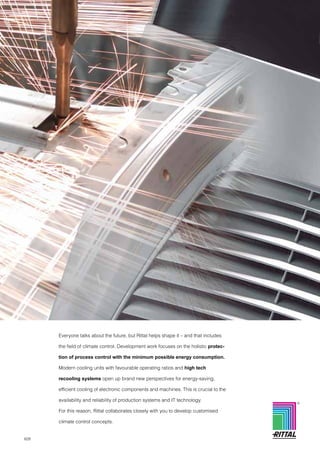
  • 1. 628 Everyone talks about the future, but Rittal helps shape it – and that includes the field of climate control. Development work focuses on the holistic protec- tion of process control with the minimum possible energy consumption. Modern cooling units with favourable operating ratios and high tech recooling systems open up brand new perspectives for energy-saving, efficient cooling of electronic components and machines. This is crucial to the availability and reliability of production systems and IT technology. For this reason, Rittal collaborates closely with you to develop customised climate control concepts. R
  • 2. 629 Rittal Catalogue 32/System Climate Control B 4. System Climate Control System Climate Control Cooling units from page 630 Features.......................................................................................... 630 Modular climate control concept Cooling module, useful cooling output 1500/2500 W..................... 633 Section doors for installing cooling modules.................................. 634 Climate control side panels ............................................................ 635 Roof-mounted cooling units Useful cooling output 500/750 W ................................................... 636 Useful cooling output 1000 W ........................................................ 637 Useful cooling output 1100/3000 W ............................................... 638 Useful cooling output 1500/2000 W ............................................... 639 Useful cooling output 3000/4000 W ............................................... 640 With CO2 as the coolant, useful cooling output 1000 W................. 653 Wall-mounted cooling units VIP small cooling units, useful cooling output 225 W..................... 641 Mini in horizontal format, useful cooling output 300 W................... 642 Useful cooling output 300/500 W ................................................... 643 Useful cooling output 750 W .......................................................... 644 Useful cooling output 1000/1500 W ............................................... 645 Slimline, useful cooling output 1500 W........................................... 646 Useful cooling output 2000/2500 W ............................................... 647 Useful cooling output 4000 W ........................................................ 648 Design NEMA 4x, useful cooling output 500/1000/1500 W............ 649 Design NEMA 4x, useful cooling output 2000/2500 W................... 650 For precision machine tools, useful cooling output 1000/1500 W ................................................ 651 Zone 22 (dust) explosion-proof cooling units, useful cooling output 1000/1500 W ................................................ 652 With CO2 as the coolant, useful cooling output 1000 W................. 653 Recooling systems from page 654 Features.......................................................................................... 654 Recooling systems Mini ................................................................................................. 656 Mini, for wall mounting.................................................................... 659 In floor-standing enclosure............................................................. 660 In floor-standing enclosure for oil ................................................... 662 In TS 8 Top enclosure system ........................................................ 664 In industrial enclosure .................................................................... 666 Chiller for IT cooling........................................................................ 667 Immersible recooling systems for oil .............................................. 669 Immersible recooling systems for emulsion ................................... 672 Heat exchangers from page 684 Features.......................................................................................... 675 Air/water heat exchangers Micro, wall-mounted ....................................................................... 676 Wall-mounted.................................................................................. 677 Roof-mounted ................................................................................. 682 Features.......................................................................................... 684 Water/water heat exchangers In TS 8 Top enclosure system ........................................................ 685 Features.......................................................................................... 686 Air/air heat exchangers Wall-mounted.................................................................................. 687 Fan-and-filter units from page 689 Features.......................................................................................... 689 Fan-and-filter units Air throughput 20/55 m3/h – 550/700 m3/h ..................................... 690 Fan-and-filter units – EMC Air throughput 20 – 700 m3/h.......................................................... 694 Climate control tailored to enclosures from page 696 Features.......................................................................................... 696 Rack-mounted cooling units for 482.6 mm (19″)......................... 698 Rack-mounted fans for 482.6 mm (19″) ....................................... 699 Centrifugal fans ............................................................................ 700 Fan systems .................................................................................. 701 Heaters from page 708 Features.......................................................................................... 708 Enclosure heaters Continuous thermal output 10 – 300 W .......................................... 709 Accessories for System Climate Control from page 710 Features.......................................................................................... 710 Accessories for system climate control Air routing ....................................................................................... 711 Control/regulation ........................................................................... 714 General ........................................................................................... 718 Filter technology for cooling units................................................... 723 Liquid cooling from page 726 Applications.................................................................................... 726 Rittal Liquid Cooling Package ..................................................... 727 Accessories for Rittal Liquid Cooling Package ......................... 729 Features.......................................................................................... 731 DCP – Direct Cooling Package .................................................... 732
  • 3. 630 Rittal Catalogue 32/System Climate Control Cooling units Features B 4.1 Cooling units Intelligent control The two controller variants for operational reliability offer a comprehensive range of func- tions. Essential control electronics are well protected and cooled in the inner circuit. Both variants have the following properties: ● Three voltage options: 115 V, 230 V, 400/460 V 3~ ● Integral start-up delay and door limit switch function ● Icing protection function ● Monitoring of all motors ● Phase monitoring for three-phase units Basic controller: ● Visualisation of the operating status via LED display ● Switching hysteresis: 5 K ● Floating fault signal contact in case of overtemperature ● Setpoint setting may be made externally via potentiometer Comfort controller: ● Switching hysteresis: 2 – 10 K preset to 5 K ● System alarm, individually configurable for 2 floating fault signal contacts ● Visualisation of the current enclosure internal tempera- ture and all system messages on the display ● Storage of all system states in the log file ● Optional extension card for integration into superordinate remote monitoring systems e. g. with CMC Rittal System Climate Control offers holistic process protec- tion. This includes the cooling of sensitive electronics in enclosures and cases for industrial process control, as well as server and network technology, regardless of the respec- tive ambient conditions. But these are not isolated solutions – with Rittal, everything is interconnected. Perfectly linked and controlled cooling technology with eco-friendly, energy- efficient equipment. Selection criteria Modular climate control door concept The unity of enclosure and cooling components achieves particularly effective cooling. Assembly time is eliminated. The investment costs for the complete unit offer exception- ally good value for money. Roof-mounted cooling units Requirement-oriented routing of cooling air in the internal circuit is possible, with up to four cold air outlet openings and the op- tional use of ducts. In the exter- nal circuit, the heated air is ex- pelled to the rear, left and right, and optionally upwards. This facilitates bayed installation, and siting close to the wall. Wall-mounted cooling units Depending on the space and design requirements, internal mounting, partial internal mount- ing and external mounting are all possible. Thanks to large dis- tances between the air intake and outlet openings, effective cold air throughput of the enclo- sure is achieved. Benefits: ● Useful cooling output from 225 W to 4000 W ● Extensive control and moni- toring features, even with the basic version ● Three-phase cooling units support multiple voltages as standard ● Uniform, output-related, cross- system mounting cut-outs, to match TopTherm air/air and air/water heat exchangers ● Targeted, individual air routing ● No assembly work and low investment costs, thanks to the complete solution con- sisting of an enclosure and integral cooling unit1) ● May be integrated directly into TS 8 bayed enclosure suites1) Important: ● Use a base/plinth of at least 100 mm height to ensure uninhibited air entry1) ● Avoid overloading the roof plate by using stays (see TS 8 system accessories) ● Air inlet and outlet openings in the internal and external circuit must not be obstructed. 1) Only for modular climate control door concept.
  • 4. Cooling units Features 631 Rittal Catalogue 32/System Climate Control B 4.1 Cooling units Flexible output Only 3 mounting cut-outs for 6 different output categories. Targeted air routing in the enclosure The heated air is centrally ex- tracted. Targeted air occurs via optional channels in the four corners, depending on require- ments. Electronic condensate evapo- ration as standard Condensate is effectively evapo- rated. Energy-efficient and resource-conserving For those who place their trust in Rittal, value-added comes as standard. What is more, Rittal is a global trendsetter in the field of climate control. A host of pioneering concepts bear witness to this fact: Rittal TopTherm cooling units are equipped as standard with innovative RiNano-coating and integral electronic conden- sate evaporation. Roof-mounted cooling units Wall-mounted cooling units Wall-mounted cooling units – practical and stylish Whether external, internal or par- tial internal mounting, optimum use is made of the available space. Effective air routing inside the enclosure Thanks to the large distance between air inlet and outlet in the internal circuit, optimum through-flow of the enclosure is ensured, thereby avoiding air short-circuits. Electronic condensate evapo- ration as standard Condensate is effectively evapo- rated. Cooling units for special applications Wall-mounted cooling units for machine tools with high acceleration rates and in- creased sensitivity to vibration. Explosion-proof wall-mounted cooing units for Zone 22 (dust). Roof-mounted cooling units – specifically for office applica- tions with a considerably lower noise level.
  • 5. 632 Rittal Catalogue 32/System Climate Control Modular climate control concept Features B 4.1 Modular climate control concept 1 2 600 1800/2000 800 1800/2000 1200 1800/2000 1200 1800/2000 3 4 6 5 Less is more! With only six cooling modules and eight door modules, we are now able to provide you with a virtually infi- nite variety of applications. The best cooling technology, complete and ready for use – without having to make mount- ing cut-outs. The existing sheet steel doors can simply be changed for the section doors with the cooling modules. These can also be exchanged or upgraded during operation. Your benefits: ● Modular design – for individ- ual size, cooling power and voltage combinations ● Simple, fast mounting ● Service-friendly (front rack- mounted filter and remova- ble cover) ● Quick delivery Our concept: ● TS 8 section door and cli- mate control combination ● One item number each for the door and climate control module ● 8 section doors x 6 climate control modules = 48 combi- nation options ● Standard RTT PLUS version with integral condensate evaporation and RiNano- coating Infinite possibilities Seamless baying and perfect integration. The TS base/plinth is required for operation. Comfort controller Optimum function and control monitoring. Modularity Your individual climate control solution can be produced from the section door and the cli- mate control module in just a few steps. Climate control module, 1500 W useful cooling output Climate control module, 2500 W useful cooling output Section doors for installing climate control modules in 600 mm wide enclosures Section doors for installing climate control modules in 800 mm wide enclosures Section doors for installing climate control modules in 1200 mm wide enclosures; climate control module fitted on the left Section doors for installing climate control modules in 1200 mm wide enclosures; climate control module fitted on the right, including lockable door on the left 1 2 3 4 5 6 ● Intelligent control − Climate control module with Comfort controller − Controller is identical to those used with TopTherm climate control systems New modular climate control concept
  • 6. Modular climate control concept Cooling module, useful cooling output 1500/2500 W 633 Rittal Catalogue 32/System Climate Control B 4.1 Modular climate control concept Supply includes: Cooling module prepared for installation in section door, with RiNano coating and integrated condensation evaporation. Also required: Section door, fits TS 8 enclosures, 600, 800, 1200 mm widths and 1800, 2000 mm widths, see page 634. Base/plinth, 100 or 200 mm high, see page 893. Detailed drawing, see page 1276. Performance diagrams, available on the Internet. Model No. SK with Comfort controller 3307.700 3307.710 3307.740 3310.700 3310.710 3310.740 Rated operating voltage V, Hz 230, 1~, 50/60 115, 1~, 50/60 400, 3~, 50/ 460, 3~, 60 230, 1~, 50/60 115, 1~, 50/60 400, 3~, 50/ 460, 3~, 60 Useful cooling output to DIN 3168 L 35 L 35 L 35 L 50 1500 W/1550 W 950 W/1000 W 2500 W/2720 W 1620 W/1730 W 2500 W/2700 W 1900 W/1950 W Rated current max. 4.7 A/6.3 A 9.4 A/12.6 A 2.6 A/2.8 A 7.8 A/8.8 A 14.8 A/16.7 A 3.2 A/3.5 A Start-up current 22.0 A/24.0 A 36.0 A/39.0 A 8.5 A/9.2 A 22.0 A/24.0 A 36.0 A/39.0 A 12.4 A/13.5 A Pre-fuse gG 16.0 A/16.0 A 16.0 A/16.0 A 6.3 – 10.0 A1) 16.0 A/16.0 A 20.0 A/20.0 A 6.3 – 10.0 A1) Power consumption Pel as per DIN 3168 L 35 L 35 L 35 L 50 910 W/1100 W 1100 W/1250 W 940 W/1130 W 1140 W/1280 W 850 W/910 W 920 W/980 W 1410 W/1620 W 1580 W/1950 W 1460 W/1670 W 1630 W/2000 W 1380 W/1580 W 1620 W/1920 W Refrigeration factor ε = L 35 L 35 1.6 1.6 1.7 1.7 1.8 Refrigerant R134a, 700 g R134a, 900 g Permissible operating pressure p. max. 28 bar Temperature and setting range +20°C to +55°C Protection category to EN 60 529/09.2000 External circuit IP 34 Internal circuit IP 54 Duty cycle 100 % Type of connection Plug-in terminal strip Weight2) 72 kg 72 kg 75 kg 74 kg 74 kg 76 kg Colour RAL 7035 Air throughput of fans External circuit 1100 m3/h 1100 m3/h Internal circuit 520 m3/h 1100 m3/h Temperature control Comfort controller (factory setting +35°C) Accessories Packs of Page Door-operated switch 1 4127.000 1030 Filter media 1 see accessories section door 634 SK bus system for Comfort controller 1 3124.100 717 RiDiag II including cables for Comfort controller 1 3159.100 1154 Interface card for Comfort controller 1 3124.200 716 Special voltages available on request. We reserve the right to make technical modifications. 1) Motor circuit-breaker 2) Includes section door weight QK . QK/Pel . Accessories Page 710 TS 8 enclosures From page 142 Configuration software Page 1154 New modular climate control concept
  • 7. 634 Rittal Catalogue 32/System Climate Control Modular climate control concept Section doors for installing cooling modules B 4.1 Modular climate control concept B H B H B H B H Colour: RAL 7035 Supply includes: Section door unit without pre- fitted cooling module, including TS 8 hinges, door opening angle approx. 110°. Note for 1200 mm wide TS 8 enclosures: With the device positioned on the “right”, one pack consists of a section door for installing in the right-hand half of the enclo- sure plus a special lockable door for the left-hand half. With the device positioned on the “left”, one pack consists of a section door for installing in the left-hand half of the enclosure. The existing lockable door on the right may be used. Also required: Cooling module, see page 633. Base/plinth, 100 or 200 mm high, see page 893. Detailed drawing, see page 1276. Model No. SK for 1800 mm high TS enclosures 3300.040 3300.060 3300.080 3300.110 Model No. SK for 2000 mm high TS enclosures 3300.050 3300.070 3300.090 3300.120 Dimensions to fit TS enclosures Width (B) mm 600 800 1200 (unit positioned on the left) 1200 (unit positioned on the right) Accessories Packs of Filter media 1 3284.210 3284.210 3284.210 3284.210 All SK 3307.700/.710/.740 or 3310.700/.710/.740 cooling module models, see page 633, can be integrated in the section doors mentioned above. Accessories Page 710 TS 8 enclosures From page 142 Configuration software Page 1155 New modular climate control concept
  • 8. Climate control side panels Panels, for installing on 600 mm deep TS 8 enclosures, useful cooling output 1100/1400 W 635 Rittal Catalogue 32/System Climate Control B 4.1 Climate control side panels T B2 B1 H2 H1 B = Width T = Depth Supply includes: Climate control side panel with pre-fitted cooling module. Also required: Base/plinth, 100 or 200 mm high, see page 893. Optionally available: Microcontroller control with ● digital temperature indicator, ● floating contact for collective fault signal, ● connection for door operated switch for start-up delay. Automatic condensate evapora- tion. Approvals, see page 72. Performance diagrams, available on the Internet. Accessories Page 710 TS 8 enclosures From page 142 Configuration software Page 1155 Model No. SK 3331.116 3331.316 3331.1401) 3331.3401) 3331.2161) 3331.416 3331.2401) 3331.4401) Rated operating voltage V, Hz 230, 50/60 400, 2~, 50/60 230, 50/60 400, 2~, 50/60 Dimensions B1 B2 H1 H2 T 171 157 1797 1782.5 562 171 157 1997 1982.5 562 171 157 1797 1782.5 562 171 157 1997 1982.5 562 171 157 1797 1782.5 562 171 157 1997 1982.5 562 171 157 1797 1782.5 562 171 157 1997 1982.5 562 Dimensions to fit TS enclosures mm H T 1800 600 2000 600 1800 600 2000 600 1800 600 2000 600 1800 600 2000 600 Useful cooling output QK to DIN 3168 L 35 L 35 L 35 L 50 1100 W/1200 W 730 W/830 W 1400 W/1450 W 1010 W/1060 W Rated current max. 4.0 A/4.6 A 2.3 A/2.7 A 4.0 A/4.6 A 2.3 A/2.7 A Start-up current 11.0 A/12.0 A 6.4 A/6.9 A 11.0 A/12.0 A 6.4 A/6.9 A Pre-fuse T 6.0 A/6.0 A 6.0 A/6.0 A Power consumption Pel as per DIN 3168 L 35 L 35 L 35 L 50 670 W/850 W 800 W/1000 W 690 W/870 W 820 W/1020 W 710 W/910 W 810 W/1030 W 725 W/930 W 830 W/1050 W Refrigeration factor ε = L 35 L 35 1.6 2.0 1.9 Refrigerant R134a, 825 g R134a, 875 g Permissible operating pressure p. max. 25 bar 24 bar Temperature and setting range +20°C to +50°C Protection category to EN 60 529/09.2000 External circuit IP 34 Internal circuit IP 54 Duty cycle 100 % Type of connection Terminal strip Weight 58 kg 62 kg 58 kg 62 kg Colour RAL 7035 Air throughput of fans External circuit 550 m3/h Internal circuit 275 m3/h Temperature control Internal thermostat (factory setting +35°C) Accessories Packs of Page Metal filters 1 3289.200 724 Door-operated switch 1 4127.000 1030 Temperature indicator 1 3114.100 714 Air diverter 1 3213.300 713 1) Delivery times available on request. Special voltages available on request. Technical modifications reserved. . QK/Pel .
  • 9. Roof-mounted cooling units Useful cooling output 500/750 W 636 Rittal Catalogue 32/System Climate Control B 4.1 Roof-mounted cooling units 380 597 417 475 260 Supply includes: Nano-coated condenser and integral electronic condensate evaporation. Fully wired ready for connec- tion, including drilling template and assembly parts. Accessories: Roof plate for TS 8 with mounting cut-out, see page 718. Approvals, see page 73. Detailed drawing, see page 1277. Performance diagrams, available on the Internet. Model No. SK with Basic controller, RAL 7035 3382.100 3382.110 3359.100 3359.110 3359.140 Model No. SK with Comfort controller, RAL 7035 3382.500 3382.510 3359.500 3359.510 3359.540 Model No. SK with Basic controller, stainless steel1) 3382.200 3382.210 3359.200 3359.210 3359.240 Model No. SK with Comfort controller, stainless steel1) 3382.600 3382.610 3359.600 3359.610 3359.640 Rated operating voltage V, Hz 230, 1~, 50/60 115, 1~, 50/60 230, 1~, 50/60 115, 1~, 50/60 400, 2~, 50/60 Dimensions in mm WHD 597 x 417 x 380 Useful cooling output to DIN 3168 L 35 L 35 L 35 L 50 500 W/510 W 270 W/370 W 750 W/810 W 545 W/590 W Rated current max. 3.3 A/3.5 A 6.7 A/7.2 A 3.6 A/4.5 A 7.2 A/9.0 A 2.1 A/2.6 A Start-up current 9.2 A/10.2 A 18.4 A/18.4 A 10.0 A/10.7 A 20.0 A/21.4 A 5.8 A/6.2 A Pre-fuse T 10.0 A 10.0 A 10.0 A 16.0 A 6.3 A – 10.0 A2) Power consumption Pel to DIN 3168 L 35 L 35 L 35 L 50 500 W/550 W 550 W/590 W 510 W/560 W 560 W/610 W 550 W/660 W 630 W/740 W 560 W/675 W 640 W/750 W Refrigeration factor ε = L 35 L 35 1.0 1.4 Refrigerant R134a, 250 g R134a, 300 g Permissible operating pressure p. max. 25 bar Temperature and setting range +20°C to +55°C Protection category to EN 60 529/09.2000 External circuit IP 34 Internal circuit IP 54 Duty cycle 100 % Type of connection Plug-in terminal strip Weight 30 kg 35 kg 32 kg 37 kg Air throughput of fans (unimpeded air flow) External circuit 910 m3/h Internal circuit 440 m3/h Temperature control Basic or Comfort controller (factory setting +35°C) Accessories Packs of Page Filter mats 3 3286.500 723 Metal filters 1 3286.510 724 Quick-change frame 1 3286.700 719 Door-operated switch 1 4127.000 1030 SK bus system for Comfort controller 1 3124.100 717 RiDiag II including cables for Comfort controller 1 3159.100 1154 Interface card for Comfort controller 1 3124.200 716 Air ducting system 1 3286.870 711 Cover stoppers for interior air outlet 2 3286.780 712 Condensate hose 1 3301.612 720 1) Delivery times available on request. 2) Transformer protection switch. Special voltages available on request. We reserve the right to make technical modifications. QK . QK/Pel . Property rights: German registered design no. 402 02 324 German registered design no. 402 02 325 Accessories Page 710
  • 10. Useful cooling output 1000 W Roof-mounted cooling units 637 Rittal Catalogue 32/System Climate Control B 4.1 Roof-mounted cooling units 475 597 417 490 390 Supply includes: Nano-coated condenser and integral electronic condensate evaporation. Fully wired ready for connec- tion, including drilling template and assembly parts. Accessories: Roof plate for TS 8 with mounting cut-out, see page 718. Approvals, see page 73. Detailed drawing, see page 1277. Performance diagrams, available on the Internet. Model No. SK with Basic controller, RAL 7035 3383.100 3383.110 3383.140 Model No. SK with Comfort controller, RAL 7035 3383.500 3383.510 3383.540 Model No. SK with Basic controller, stainless steel1) 3383.200 3383.210 3383.240 Model No. SK with Comfort controller, stainless steel1) 3383.600 3383.610 3383.640 Rated operating voltage V, Hz 230, 1~, 50/60 115, 1~, 50/60 400, 2~, 50/60 Dimensions in mm WHD 597 x 417 x 475 Useful cooling output to DIN 3168 L 35 L 35 L 35 L 50 1000 W/1080 W 760 W/820 W Rated current max. 4.9 A/5.1 A 9.5 A/10.0 A 2.8 A/2.8 A Start-up current 15.5 A/15.5 A 25.3 A/24.3 A 8.0 A/8.8 A Pre-fuse T 10.0 A 16.0 A 6.3 A – 10.0 A2) Power consumption Pel to DIN 3168 L 35 L 35 L 35 L 50 690 W/790 W 800 W/890 W 720 W/800 W 810 W/900 W Refrigeration factor ε = L 35 L 35 1.4 Refrigerant R134a, 500 g Permissible operating pressure p. max. 25 bar Temperature and setting range +20°C to +55°C Protection category to EN 60 529/09.2000 External circuit IP 34 Internal circuit IP 54 Duty cycle 100 % Type of connection Plug-in terminal strip Weight 40 kg 46 kg 46 kg Air throughput of fans External circuit 1760 m3/h Internal circuit 440 m3/h Temperature control Basic or Comfort controller (factory setting +35°C) Accessories Packs of Page Filter mats 3 3286.500 723 Metal filters 1 3286.510 724 Quick-change frame 1 3286.800 719 Door-operated switch 1 4127.000 1030 SK bus system for Comfort controller 1 3124.100 717 RiDiag II including cables for Comfort controller 1 3159.100 1154 Interface card for Comfort controller 1 3124.200 716 Air ducting system 1 3286.870 711 Cover stoppers for interior air outlet 2 3286.880 712 Condensate hose 1 3301.612 720 1) Delivery times available on request. 2) Transformer protection switch. Special voltages available on request. We reserve the right to make technical modifications. QK . QK/Pel . Property rights: German registered design no. 402 02 324 German registered design no. 402 02 325 Accessories Page 710
  • 11. Roof-mounted cooling units Useful cooling output 1100 W/3000 W 638 Rittal Catalogue 32/System Climate Control B 4.1 Roof-mounted cooling units 475 597 417 490 390 900 597 454 392 692 Especially for office applica- tions. Low noise level (consider- ably quieter than cooling units for industrial applications). Supply includes: Nano-coated condenser and integral electronic condensate evaporation. Fully wired ready for connection, including drilling template and assembly parts. Property rights: (Not with SK 3301.800) German registered design no. 402 02 324 German registered design no. 402 02 325 Accessories: Roof plate for TS 8 with mounting cut-out, see page 718. Approvals, see page 73. Detailed drawing, see page 1277. Performance diagrams, available on the Internet. Model No. SK with Comfort controller 3273.500 3273.5151) 3301.800 Rated operating voltage V, Hz 230, 1~, 50/60 115, 1~, 50/60 230, 1~, 50 Dimensions in mm WHD 597 x 417 x 475 515 x 400 x 990/597 x 454 x 900 Useful cooling output to DIN 3168 L 35 L 35 L 35 L 50 1100 W/1200 W 850 W/870 W 3100 W/3200 W 2400 W/2550 W Rated current max. 5.2 A/5.4 A 11.0 A/11.5 A 9.7 A Start-up current 15.5 A/16.5 A 32.0 A/35.0 A 19.0 A Pre-fuse T gG 10.0 A 20.0 A Motor circuit breaker 10.0 A/10.0 A Power consumption Pel to DIN 3168 L 35 L 35 L 35 L 50 890 W/910 W 960 W/1100 W 920 W/940 W 990 W/1140 W 1200 W/1500 W 1400 W/1750 W Refrigeration factor ε = L 35 L 35 1.2 3.1 Refrigerant R134a, 700 g R134a, 1200 g Permissible operating pressure p. max. 25 bar Temperature and setting range +20°C to +55°C Protection category to EN 60 529/09.2000 External circuit IP 34 Internal circuit IP 542) Duty cycle 100 % Type of connection Plug-in terminal strip Weight 42 kg 47 kg 72 kg Colour RAL 7035 Air throughput of fans External circuit 1760 m3/h 2000 m3/h Internal circuit 440 m3/h 1420 m3/h Temperature control Basic or Comfort controller (factory setting +35°C) Accessories Packs of Page Filter mats 3 3286.500 3286.600 723 Metal filters 1 3286.510 3286.610 724 Door-operated switch 1 4127.000 1030 SK bus system for Comfort controller 1 3124.100 717 RiDiag II including cables for Comfort controller 1 3159.100 1154 Interface card for Comfort controller 1 3124.200 716 Air ducting system 1 3286.870 3286.970 711 Cover stoppers for interior air outlet 2 3286.880 3286.980 712 Condensate hose 1 3301.612 720 1) Delivery times on request. 2) In order to avoid increased condensation, we recommend enclosures with a protection category of at least IP 54. Special voltages available on request. We reserve the right to make technical modifications. QK . QK/Pel . Accessories Page 710
  • 12. Useful cooling output 1500/2000 W Roof-mounted cooling units 639 Rittal Catalogue 32/System Climate Control B 4.1 Roof-mounted cooling units 475 597 417 490 390 Supply includes: Nano-coated condenser and integral electronic condensate evaporation. Fully wired ready for connection, including drilling template and assembly parts. Accessories: Roof plate for TS 8 with mounting cut-out, see page 718. Approvals, see page 73. Detailed drawing, see page 1277. Performance diagrams, available on the Internet. Model No. SK with Basic controller, RAL 7035 3384.100 3384.110 3384.140 3385.100 3385.110 3385.140 Model No. SK with Comfort controller, RAL 7035 3384.500 3384.510 3384.540 3385.500 3385.510 3385.540 Model No. SK with Basic controller, stainless steel1) 3384.200 3384.210 3384.240 3385.200 3385.210 3385.240 Model No. SK with Comfort controller, stainless steel1) 3384.600 3384.610 3384.640 3385.600 3385.610 3385.640 Rated operating voltage V, Hz 230, 1~, 50/60 115, 1~, 50/60 400, 2~, 50/60 230, 1~, 50/60 115, 1~, 50/60 400, 2~, 50/60 Dimensions in mm WHD 597 x 417 x 475 597 x 417 x 475 Useful cooling output to DIN 3168 L 35 L 35 L 35 L 50 1500 W/1520 W 1100 W/1210 W 2000 W/2130 W 1570 W/1670 W Rated current max. 6.3 A/7.4 A 13.7 A/15.3 A 3.8 A/4.4 A 6.3 A/7.2 A 14.2 A/15.4 A 3.7 A/4.2 A Start-up current 16.6 A/17.1 A 30.7 A/29.1 A 9.8 A/9.6 A 16.8 A/18.4 A 36.0 A/32.0 A 10.0 A/12.0 A Pre-fuse T 10.0 A 20.0 A 6.3 A – 10.0 A2) 10.0 A 20.0 A 6.3 A – 10.0 A2) Power consumption Pel to DIN 3168 L 35 L 35 L 35 L 50 955 W/1070 W 1090 W/1230 W 990 W/1090 W 1140 W/1290 W 1140 W/1310 W 1240 W/1450 W 1190 W/1390 W 1300 W/1520 W Refrigeration factor ε = L 35 L 35 1.6 1.5 1.8 1.7 Refrigerant R134a, 500 g R134a, 950 g Permissible operating pressure p. max. 25 bar Temperature and setting range +20°C to +55°C Protection category to EN 60 529/09.2000 External circuit IP 34 Internal circuit IP 54 Duty cycle 100 % Type of connection Plug-in terminal strip Weight 41 kg 47 kg 47 kg 42 kg 48 kg 48 kg Air throughput of fans External circuit 1760 m3/h 1820 m3/h Internal circuit 470 m3/h Temperature control Basic or Comfort controller (factory setting +35°C) Accessories Packs of Page Filter mats 3 3286.500 723 Metal filters 1 3286.510 724 Quick-change frame 1 3286.800 719 Door-operated switch 1 4127.000 1030 SK bus system for Comfort controller 1 3124.100 717 RiDiag II including cables for Comfort controller 1 3159.100 1154 Interface card for Comfort controller 1 3124.200 716 Air ducting system 1 3286.870 711 Cover stoppers for interior air outlet 2 3286.880 712 Condensate hose 1 3301.612 720 1) Delivery times available on request. 2) Transformer protection switch. Special voltages available on request. We reserve the right to make technical modifications. QK . QK/Pel . Property rights: German registered design no. 402 02 324 German registered design no. 402 02 325 Accessories Page 710
  • 13. Roof-mounted cooling units Useful cooling output 3000/4000 W 640 Rittal Catalogue 32/System Climate Control B 4.1 Roof-mounted cooling units 580 796 470 692 392 Supply includes: Nano-coated condenser and integral electronic condensate evaporation. Fully wired ready for connec- tion, including drilling template, eyebolt and assembly parts. Accessories: Roof plate for TS 8 with mounting cut-out, see page 718. Approvals, see page 73. Detailed drawing, see page 1277. Performance diagrams, available on the Internet. Model No. SK with Basic controller, RAL 7035 3386.140 3387.140 Model No. SK with Comfort controller, RAL 7035 3386.540 3387.540 Model No. SK with Basic controller, stainless steel1) 3386.240 3387.240 Model No. SK with Comfort controller, stainless steel1) 3386.640 3387.640 Rated operating voltage V, Hz 400, 3~, 50/460, 3~, 60 400, 3~, 50/460, 3~, 60 Dimensions in mm WHD 796 x 470 x 580 796 x 470 x 580 Useful cooling output to DIN 3168 L 35 L 35 L 35 L 50 3000 W/3300 W 2200 W/2500 W 4000 W/4200 W 3250 W/3490 W Rated current max. 3.4 A/3.4 A 3.9 A/3.9 A Start-up current 8.0 A/9.0 A 17.0 A/19.0 A Pre-fuse T Motor circuit breaker 6.3 A – 10.0 A Power consumption Pel to DIN 3168 L 35 L 35 L 35 L 50 1320 W/1630 W 1570 W/1910 W 1760 W/2200 W 2010 W/2480 W Refrigeration factor ε = L 35 L 35 2.3 Refrigerant R134a, 1600 g R134a, 1800 g Permissible operating pressure p. max. 25 bar Temperature and setting range +20°C to +55°C Protection category to EN 60 529/09.2000 External circuit IP 34 Internal circuit IP 54 Duty cycle 100 % Type of connection Plug-in terminal strip Weight 70 kg 77 kg Air throughput of fans External circuit 3450 m3/h 3870 m3/h Internal circuit 1280 m3/h 1420 m3/h Temperature control Basic or Comfort controller (factory setting +35°C) Accessories Packs of Page Filter mats 3 3286.600 723 Metal filters 1 3286.610 724 Quick-change frame 1 3286.900 719 Door-operated switch 1 4127.000 1030 SK bus system for Comfort controller 1 3124.100 717 RiDiag II including cables for Comfort controller 1 3159.100 1154 Interface card for Comfort controller 1 3124.200 716 Air ducting system 1 3286.970 711 Cover stoppers for interior air outlet 2 3286.980 712 Condensate hose 1 3301.612 720 1) Delivery times available on request. Special voltages available on request. We reserve the right to make technical modifications. QK . QK/Pel . Property rights: German registered design no. 402 02 324 German registered design no. 402 02 325 Accessories Page 710
  • 14. VIP small cooling units, useful cooling output 225 W Wall-mounted cooling units 641 Rittal Catalogue 32/System Climate Control B 4.1 Wall-mounted cooling units 526 353.5 288 465 105 32 183 296 288 465 183 32 353.5 296 105 1 1 60 60 The new VIP SK small cooling units were developed especially for cooling the VIP 6000 com- mand panel. In addition, VIP small cooling units also offer a space-saving, economical solu- tion for the climate control of small enclosures where small heat loads are generated by the system. Supply includes: Fully wired ready for connection and pre-mounted on an alumin- ium rear panel to fit VIP 6000 operating housing 7 U. Property rights: German patent no. 198 17 917 Distance from installed equipment at least 60 mm Approvals, see page 74. Performance diagrams, available on the Internet. 1 Model No. SK 3201.100 3202.100 Condenser version Left Right Rated operating voltage V, Hz 230, 50/60 Dimensions in mm W H D 526 353.5 105 Useful cooling output to DIN 3168 L 35 L 35 L 35 L 45 225 W/270 W 160 W/200 W Rated current max. 1.5 A/1.5 A Start-up current 1.9 A/2.0 A Pre-fuse T 4.0 A/4.0 A Power consumption Pel to DIN 3168 L 35 L 35 L 35 L 45 285 W/300 W 315 W/325 W Refrigeration factor ε = L 35 L 35 0.8/0.9 Refrigerant R134a, 170 g Permissible operating pressure p. max. 27 bar Temperature and setting range +20°C to +45°C Protection category to EN 60 529/09.2000 External circuit IP 24 Internal circuit IP 54 Duty cycle 100 % Type of connection Terminal strip Weight 10.5 kg Colour Rear panel aluminium, vent grille RAL 7035 Air throughput of fans External circuit 235 m3/h / 270 m3/h Internal circuit 160 m3/h / 180 m3/h Temperature control Electronic control (factory setting +35°C) Accessories Packs of Page Temperature indicator 1 3114.100 714 Condensate hose 1 3301.608 720 Special voltages available on request. We reserve the right to make technical modifications. QK . QK/Pel . Accessories Page 710 Configuration software Page 1155
  • 15. Wall-mounted cooling units Mini in horizontal format, useful cooling output 300 W 642 Rittal Catalogue 32/System Climate Control B 4.1 Wall-mounted cooling units 340 525 153 98 55 Mini cooling units in horizontal format, ideal for cooling small enclosures and operating hous- ings with optimum space utilisa- tion. Supply includes: Nano-coated condenser. Fully wired ready for connection, including drilling template and assembly parts. Approvals, see page 74. Detailed drawing, see page 1278. Performance diagrams, available on the Internet. Model No. SK 3302.300 3302.310 Rated operating voltage V, Hz 230, 1~, 50/60 115, 1~, 60 Dimensions in mm W H D 525 340 153 Useful cooling output to DIN 3168 L 35 L 35 L 35 L 50 300 W/320 W 150 W/160 W 300 W 150 W Rated current max. 1.6 A/1.7 A 4.0 A Start-up current 4.3 A/5.3 A 12.0 A Pre-fuse T 10.0 A 10.0 A Power consumption Pel to DIN 3168 L 35 L 35 L 35 L 50 285 W/300 W 320 W/340 W 290 W 340 W Refrigeration factor ε = L 35 L 35 1.1 Refrigerant R134a, 100 g R134a, 95 g Permissible operating pressure p. max. 25 bar Temperature and setting range +20°C to +55°C Protection category to EN 60 529/09.2000 External circuit IP 34 Internal circuit IP 54 Duty cycle 100 % Type of connection Plug-in terminal strip Weight 13 kg Colour RAL 7035 Air throughput of fans External circuit 345 m3/h Internal circuit 310 m3/h Temperature control Basic controller Accessories Packs of Page Temperature indicator 1 3114.100 714 Condensate hose 1 3301.608 720 Filter mats 3 3286.110 723 Metal filters 1 3286.120 724 Special voltages available on request. We reserve the right to make technical modifications. QK . QK/Pel . Accessories Page 710 Configuration software Page 1155
  • 16. Useful cooling output 300/500 W Wall-mounted cooling units 643 Rittal Catalogue 32/System Climate Control B 4.1 Wall-mounted cooling units T2 42 550 T 280 100 110 1 B = Width T = Depth Supply includes: Nano-coated condenser. Fully wired ready for connection, including drilling template and assembly parts. Partial internal mounting possible with 3303.XXX only. Approvals, see page 75. Detailed drawing, see page 1278. Performance diagrams, available on the Internet. Property rights: German registered design no. 402 02 324 and no. 402 02 325 Japanese registered design no. 1 187 896 Indian registered design no. 189 953 US design patent no. D 488,480 IR reg. design no. DM/061 967 with validity for FR, IT, ES 1 Model No. SK with Basic controller, RAL 7035 3302.100 3302.110 3303.100 3303.110 Model No. SK with Comfort controller, RAL 7035 – – 3303.500 3303.510 Model No. SK with Basic controller, stainless steel1) 3302.200 3302.210 3303.200 3303.210 Model No. SK with Comfort controller, stainless steel1) – – 3303.600 3303.610 Rated operating voltage V, Hz 230, 1~, 50/60 115, 1~, 60 230, 1~, 50/60 115, 1~, 60 Dimensions in mm B H T T2 280 550 140 98 280 550 210 164 Useful cooling output to DIN 3168 L 35 L 35 L 35 L 50 300 W/320 W 150 W/170 W 300 W 150 W 500 W/610 W 280 W/350 W 500 W 280 W Rated current max. 1.6 A/1.7 A 3.3 A 2.6 A/2.6 A 5.7 A Start-up current 3.0 A/3.4 A 8.0 A 5.1 A/6.4 A 11.5 A Pre-fuse T 10.0 A 10.0 A 10.0 A 10.0 A Power consumption Pel to DIN 3168 L 35 L 35 L 35 L 50 245 W/255 W 255 W/275 W 290 W 340 W 360 W/380 W 420 W/390 W 470 W 500 W Refrigeration factor ε = L 35 L 35 1.2 1.4 Refrigerant R134a, 100 g R134a, 170 g Permissible operating pressure p. max. 25 bar 28 bar Temperature and setting range +20°C to +55°C Protection category to EN 60 529/09.2000 External circuit IP 34 Internal circuit IP 54 Duty cycle 100 % Type of connection Plug-in terminal strip Weight 13 kg 17 kg Air throughput of fans External circuit 310 m3/h 345 m3/h Internal circuit 345 m3/h 310 m3/h Temperature control Basic or Comfort controller (factory setting +35°C) Accessories Packs of Page Filter mats 3 3286.300 723 Metal filters 1 3286.310 724 Door-operated switch 1 4127.000 1030 SK bus system for Comfort controller 1 – 3124.100 717 RiDiag II including cables for Comfort controller 1 – 3159.100 1154 Interface card for Comfort controller 1 – 3124.200 716 Condensate hose 1 3301.608 3301.610 720 1) Delivery times available on request. Special voltages available on request. We reserve the right to make technical modifications. QK . QK/Pel . Accessories Page 710 Configuration software Page 1155
  • 17. Wall-mounted cooling units Useful cooling output 750 W 644 Rittal Catalogue 32/System Climate Control B 4.1 Wall-mounted cooling units 235 45 550 280 280 125 155 Supply includes: Nano-coated condenser. Fully wired ready for connection, including drilling template and assembly parts. Approvals, see page 75. Detailed drawing, see page 1278. Performance diagrams, available on the Internet. Property rights: German registered design no. 402 02 324 and no. 402 02 325 Japanese registered design no. 1 187 896 Indian registered design no. 189 953 US design patent no. D 488,480 IR reg. design no. DM/061 967 with validity for FR, IT, ES Model No. SK with Basic controller, RAL 7035 3361.100 3361.110 3361.140 Model No. SK with Comfort controller, RAL 7035 3361.500 3361.510 3361.540 Model No. SK with Basic controller, stainless steel1) 3361.200 3361.210 3361.240 Model No. SK with Comfort controller, stainless steel1) 3361.600 3361.610 3361.640 Rated operating voltage V, Hz 230, 1~, 50/603) 115, 1~, 603) 4002), 2~, 50/603) Dimensions in mm W H D 280 550 280 Useful cooling output to DIN 3168 L 35 L 35 L 35 L 50 750 W/780 W 510 W/540 W 750 W 500 W 750 W/780 W 510 W/540 W Rated current max. 2.3 A/2.4 A 5.3 A 1.2 A/1.4 A Start-up current 5.6 A/5.6 A 12.0 A 3.1 A/3.3 A Pre-fuse T 10.0 A 10.0 A 6.3 A – 10.0 A4) Power consumption Pel to DIN 3168 L 35 L 35 L 35 L 50 480 W/550 W 530 W/640 W 570 W 670 W 480 W/550 W 530 W/640 W Refrigeration factor ε = L 35 L 35 1.5 Refrigerant R134a, 280 g R134a, 260 g R134a, 280 g Permissible operating pressure p. max. 28 bar Temperature and setting range +20°C to +55°C Protection category to EN 60 529/09.2000 External circuit IP 34 Internal circuit IP 54 Duty cycle 100 % Type of connection Plug-in terminal strip Weight 22 kg Air throughput of fans (unimpeded air flow) External circuit 480 m3/h Internal circuit 600 m3/h Temperature control Basic or Comfort controller (factory setting +35°C) Accessories Packs of Page Filter mats 3 3286.300 723 Metal filters 1 3286.310 724 Door-operated switch 1 4127.000 1030 SK bus system for Comfort controller 1 3124.100 717 RiDiag II including cables for Comfort controller 1 3159.100 1154 Interface card for Comfort controller 1 3124.200 716 Condensate hose 1 3301.610 720 1) Delivery times on request. 2) External toroidal core transformer Ø 126 x 65 mm deep for mounting in the enclosure. 3) Tu max. = 52°C/60 Hz. 4) Transformer protection switch. Special voltages available on request. Technical modifications reserved. QK . QK/Pel . Accessories Page 710 Configuration software Page 1155
  • 18. Useful cooling output 1000/1500 W Wall-mounted cooling units 645 Rittal Catalogue 32/System Climate Control B 4.1 Wall-mounted cooling units 105 155 210 50 950 260 400 Supply includes: Nano-coated condenser and integral electronic condensate evaporation. Fully wired ready for connection, including drilling template and assembly parts. Approvals, see page 75. Detailed drawing, see page 1279. Performance diagrams, available on the Internet. Property rights: German registered design no. 402 02 325 IR reg. design no. DM/062 557 with validity for FR, IT, ES Indian registered design no. 190 269 Japanese registered design no. 1 187 905 Model No. SK with Basic controller, RAL 7035 3304.100 3304.110 3304.140 3305.100 3305.110 3305.140 Model No. SK with Comfort controller, RAL 7035 3304.500 3304.510 3304.540 3305.500 3305.5101) 3305.540 Model No. SK with Basic controller, stainless steel1) 3304.200 3304.210 3304.240 3305.200 3305.210 3305.240 Model No. SK with Comfort controller, stainless steel1) 3304.600 3304.610 3304.640 3305.600 3305.610 3305.640 Rated operating voltage V, Hz 230, 1~, 50/60 115, 1~, 50/60 400, 3~, 50/ 460, 3~, 60 230, 1~, 50/60 115, 1~, 50/60 400, 3~, 50/ 460, 3~, 60 Dimensions in mm W H D 400 950 260 400 950 260 Useful cooling output to DIN 3168 L 35 L 35 L 35 L 50 1000 W/1060 W 790 W/840 W 1500 W/1510 W 1230 W/1250 W Rated current max. 5.4 A/5.0 A 10.6 A/11.1 A 2.8 A/2.9 A 6.0 A/6.5 A 12.1 A/13.6 A 2.6 A/2.9 A Start-up current 12.0 A/14.0 A 26.0 A/28.0 A 11.5 A/12.7 A 22.0 A/24.0 A 42.0 A/46.0 A 12.2 A/11.3 A Pre-fuse T 10.0 A 16.0 A 6.3 A – 10.0 A2) 16.0 A 20.0 A 6.3 A – 10.0 A2) Power consumption Pel to DIN 3168 L 35 L 35 L 35 L 50 825 W/775 W 875 W/835 W 850 W/800 W 900 W/875 W 700 W/675 W 785 W/800 W 975 W/1125 W 1125 W/1285 W 1000 W/1175 W 1165 W/1325 W 925 W/1100 W 1085 W/1275 W Refrigeration factor ε = L 35 L 35 1.2 1.4 1.5 1.6 Refrigerant R134a, 325 g R134a, 500 g R134a, 600 g Permissible operating pressure p. max. 25 bar Temperature and setting range +20°C to +55°C Protection category to EN 60 529/09.2000 External circuit IP 34 Internal circuit IP 54 Duty cycle 100 % Type of connection Plug-in terminal strip Weight 39 kg 44 kg 40 kg 41 kg 46 kg 42 kg Air throughput of fans External circuit 900 m3/h Internal circuit 600 m3/h 800 m3/h Temperature control Basic or Comfort controller (factory setting +35°C) Accessories Packs of Page Filter mats 3 3286.400 723 Metal filters 1 3286.410 724 Door-operated switch 1 4127.000 1030 SK bus system for Comfort controller 1 3124.100 717 RiDiag II including cables for Comfort controller 1 3159.100 1154 Interface card for Comfort controller 1 3124.200 716 Condensate hose 1 3301.612 720 1) Delivery times available on request. 2) Motor circuit-breaker. Special voltages available on request. We reserve the right to make technical modifications. QK . QK/Pel . Accessories Page 710 Configuration software Page 1155
  • 19. Wall-mounted cooling units Slimline, useful cooling output 1500 W 646 Rittal Catalogue 32/System Climate Control B 4.1 Wall-mounted cooling units 1590 205 435 140 65 1590 165 435 140 25 ● Simple, fast assembly without the need to drill additional holes ● Ideal for restricted mounting locations ● Super-slimline design ● Minimal installation depth and build height. Supply includes: Nano-coated condenser and integral electronic condensate evaporation. Fully wired ready for connection, including drilling template and assembly parts. Approvals, see page 75. Detailed drawing, see page 1280. Performance diagrams, available on the Internet. Model No. SK with Basic controller, RAL 7035 3366.100 3377.1001) 3366.110 3377.1101) 3366.140 3377.1401) Model No. SK with Comfort controller, RAL 7035 3366.500 3377.5001) 3366.510 3377.5101) 3366.540 3377.5401) Model No. SK with Basic controller, stainless steel 3366.2001) 3377.2001) 3366.2101) 3377.2101) 3366.2401) 3377.2401) Model No. SK with Comfort controller, stainless steel 3366.6001) 3377.6001) 3366.6101) 3377.6101) 3366.6401) 3377.6401) Rated operating voltage V, Hz 230, 1~, 50/60 115, 1~, 50/60 400, 3~, 50/460, 3~, 60 Dimensions in mm W H D 435 1590 205 435 1590 165 435 1590 205 435 1590 165 435 1590 205 435 1590 165 Useful cooling output to DIN 3168 L 35 L 35 L 35 L 50 1500 W/1500 W 1050 W/1100 W 1500 W/1500 W 980 W/1080 W Rated current max. 7.1 A/7.3 A 14.3 A/14.7 A 3.0 A/3.1 A Start-up current 22.0 A/24.0 A 43.0 A/47.0 A 8.0 A/8.8 A Pre-fuse T 10.0 A 20.0 A 6.3 A – 10.0 A2) Power consumption Pel to DIN 3168 L 35 L 35 L 35 L 50 1045 W/1175 W 1220 W/1335 W 1075 W/1200 W 1265 W/1375 W 1090 W/1240 W 1260 W/1430 W Refrigeration factor ε = L 35 L 35 1.4 1.3 Refrigerant R134a, 700 g Permissible operating pressure p. max. 28 bar Temperature and setting range +20°C to +55°C Protection category to EN 60 529/09.2000 External circuit IP 34 Internal circuit IP 54 Duty cycle 100 % Type of connection Plug-in terminal strip Weight 45 kg 50 kg 46 kg Air throughput of fans (unimpeded air flow) External circuit 910 m3/h Internal circuit 860 m3/h Temperature control Basic or Comfort controller (factory setting +35°C) Accessories Packs of Page Filter mats 3 3286.400 3253.010 3286.400 3253.010 3286.400 3253.010 723 Metal filters 1 3286.410 3253.220 3286.410 3253.220 3286.410 3253.220 724 Trim frame for external device mounting 1 3377.000 719 Door-operated switch 1 4127.000 1030 SK bus system for Comfort controller 1 3124.100 717 RiDiag II including cables for Comfort controller 1 3159.100 1154 Interface card for Comfort controller 1 3124.200 716 Condensate hose 1 3301.612 720 1) Delivery times available on request. 2) Motor circuit-breaker. Special voltages available on request. Technical modifications reserved. QK . QK/Pel . Accessories Page 710 Configuration software Page 1155
  • 20. Useful cooling output 2000/2500 W Wall-mounted cooling units 647 Rittal Catalogue 32/System Climate Control B 4.1 Wall-mounted cooling units 400 40 1580 295 145 150 245 50 Supply includes: Nano-coated condenser and integral electronic condensate evaporation. Fully wired ready for connection, including drilling template, eyebolt and assembly parts. Also required: For installation in the door, we recommend the use of the ride- up roller and 180° hinges (TS 8800.710), see page 961, and for use in the side panel we recommend the use of the TS enclosure panel fasteners (TS 8800.071), see page 918. Approvals, see page 75. Detailed drawing, see page 1279. Performance diagrams, available on the Internet. Model No. SK with Basic controller, RAL 7035 3328.100 3328.110 3328.140 3329.100 3329.110 3329.140 Model No. SK with Comfort controller, RAL 7035 3328.500 3328.510 3328.540 3329.500 3329.510 3329.540 Model No. SK with Basic controller, stainless steel1) 3328.200 3328.210 3328.240 3329.200 3329.210 3329.240 Model No. SK with Comfort controller, stainless steel1) 3328.600 3328.610 3328.640 3329.600 3329.610 3329.640 Rated operating voltage V, Hz 230, 1~, 50/60 115, 1~, 50/60 400, 3~, 50/ 460, 3~, 60 230, 1~, 50/60 115, 1~, 50/60 400, 3~, 50/ 460, 3~, 60 Dimensions in mm W H D 400 1580 295 400 1580 295 Useful cooling output to DIN 3168 L 35 L 35 L 35 L 50 2000 W/2350 W 1450 W/1690 W 2500 W/2750 W 1600 W/1750 W 2500 W/2700 W 1900 W/1950 W Rated current max. 7.5 A/9.1 A 14.7 A/17.3 A 2.8 A/3.3 A 8.6 A/10.6 A 17.0 A/22.0 A 3.7 A/3.8 A Start-up current 22.0 A/26.0 A 36.0 A/39.0 A 6.8 A/7.8 A 21.0 A/21.0 A 44.0 A/42.0 A 6.8 A/7.6 A Pre-fuse T 16.0 A 25.0 A 6.3 A – 10.0 A2) 16.0 A 25.0 A 6.3 A – 10.0 A2) Power consumption Pel to DIN 3168 L 35 L 35 L 35 L 50 1025 W/1200 W 1250 W/1350 W 1085 W/1250 W 1300 W/1410 W 1050 W/1275 W 1275 W/1525 W 1450 W/1675 W 1625 W/2000 W 1500 W/1725 W 1675 W/2065 W 1425 W/1625 W 1675 W/1975 W Refrigeration factor ε = L 35 L 35 2.0 1.8 1.9 1.7 1.8 Refrigerant R134a, 950 g Permissible operating pressure p. max. 28 bar Temperature and setting range +20°C to +55°C Protection category to EN 60 529/09.2000 External circuit IP 34 Internal circuit IP 54 Duty cycle 100 % Type of connection Plug-in terminal strip Weight 66 kg 73 kg 67 kg 69 kg 76 kg 70 kg Air throughput of fans External circuit 640 m3/h 710 m3/h Internal circuit 550 m3/h 640 m3/h Temperature control Basic or Comfort controller (factory setting +35°C) Accessories Packs of Page Filter mats 3 3286.400 723 Metal filters 1 3286.410 724 Door-operated switch 1 4127.000 1030 SK bus system for Comfort controller 1 3124.100 717 RiDiag II including cables for Comfort controller 1 3159.100 1154 Interface card for Comfort controller 1 3124.200 716 Condensate hose 1 3301.612 720 1) Delivery times available on request. 2) Motor circuit-breaker. Special voltages available on request. Technical modifications reserved. QK . QK/Pel . Accessories Page 710 Configuration software Page 1155
  • 21. Wall-mounted cooling units Useful cooling output 4000 W 648 Rittal Catalogue 32/System Climate Control B 4.1 Wall-mounted cooling units 1580 340 500 145 195 Supply includes: Nano-coated condenser and integral electronic condensate evaporation. Fully wired ready for connection, including drilling template, eyebolt and assembly parts. Note: External mounting and partial internal mounting of the cooling unit are available as standard. Partial internal mounting not possible with: – 600 mm wide TS enclosures and – 1200 mm wide TS enclosures in the lockable door. Also required: When mounting in the door: Ride-up roller (TS 4538.000), see page 967. When fitted with 180° hinges (TS 8800.710), see page 961. When mounting in the side panel: Enclosure panel fasteners (TS 8800.071), see page 918. Approvals, see page 75. Detailed drawing, see page 1279. Performance diagrams, available on the Internet. Model No. SK with Basic controller, RAL 7035 3332.140 Model No. SK with Comfort controller, RAL 7035 3332.540 Model No. SK with Basic controller, stainless steel1) 3332.240 Model No. SK with Comfort controller, stainless steel1) 3332.640 Rated operating voltage V, Hz 400, 3~, 50/460, 3~, 60 Dimensions in mm W H D 500 1580 340 Useful cooling output to DIN 3168 L 35 L 35 L 35 L 50 4000 W/4400 W 3070 W/3570 W Rated current max. 4.2 A/4.2 A Start-up current 9.2 A/11.0 A Pre-fuse T Motor circuit breaker 6.3 A – 10.0 A Power consumption Pel to DIN 3168 L 35 L 35 L 35 L 50 1850 W/2250 W 2120 W/2590 W Refrigeration factor ε = L 35 L 35 2.1 Refrigerant R134a, 3000 g Permissible operating pressure p. max. 28 bar Temperature and setting range +20°C to +55°C Protection category to EN 60 529/09.2000 External circuit IP 34 Internal circuit IP 54 Duty cycle 100 % Type of connection Plug-in terminal strip Weight 91 kg Air throughput of fans External circuit 2000 m3/h Internal circuit 1500 m3/h Temperature control Basic or Comfort controller (factory setting +35°C) Accessories Packs of Page Filter mats 3 3286.400 723 Metal filters 1 3286.410 724 Door-operated switch 1 4127.000 1030 SK bus system for Comfort controller 1 3124.100 717 RiDiag II including cables for Comfort controller 1 3159.100 1154 Interface card for Comfort controller 1 3124.200 716 Condensate hose 1 3301.612 720 1) Delivery times available on request. Special voltages available on request. Technical modifications reserved. QK . QK/Pel . Accessories Page 710 Configuration software Page 1155
  • 22. Design NEMA 4x, useful cooling output 500/1000/1500 W Wall-mounted cooling units 649 Rittal Catalogue 32/System Climate Control B 4.1 Wall-mounted cooling units 238 298 285 620 298 358 405 1020 Supply includes: Nano-coated condenser and integral electronic condensate evaporation. Fully wired ready for connection, including drilling template and assembly parts. Approvals, see page 77. Detailed drawing, see page 1280. Performance diagrams, available on the Internet. Model No. SK with Basic controller1) 3303.104 3303.114 3304.104 3304.114 3304.144 3305.104 3305.114 3305.144 Model No. SK with Comfort controller1) 3303.504 3303.514 3304.504 3304.514 3304.544 3305.504 3305.514 3305.544 Rated operating voltage V, Hz 230, 1~, 50/60 115, 1~, 60 230, 1~, 50/60 115, 1~, 50/60 400, 3~, 50/ 460, 3~, 60 230, 1~, 50/60 115, 1~, 50/60 400, 3~, 50/ 460, 3~, 60 Dimensions in mm W H D 285 620 298 405 1020 358 405 1020 358 Useful cooling output to DIN 3168 L 35 L 35 L 35 L 50 500 W/610 W 280 W/350 W 500 W 280 W 1000 W/1060 W 790 W/840 W 1500 W/1510 W 1230 W/1250 W Rated current max. 2.6/2.6 A 5.7 A 5.4/5.0 A 10.6/11.1 A 2.8/2.9 A 6.0/6.5 A 12.1/13.6 A 2.6/2.9 A Start-up current 5.1/6.4 A 11.5 A 12.0/14.0 A 26.0/28.0 A 11.5/12.7 A 22.0/24.0 A 42.0/46.0 A 12.2/11.3 A Pre-fuse T 10.0 A 10.0 A 10.0 A 16.0 A 6.3 A – 10.0 A2) 16.0 A 20.0 A 6.3 A – 10.0 A2) Power consumption Pel to DIN 3168 L 35 L 35 L 35 L 50 360/380 W 420/390 W 470 W 500 W 825/775 W 875/835 W 850/800 W 900/875 W 700/675 W 785/800 W 975/1125 W 1125/1285 W 1000/1175 W 1165/1325 W 925/1100 W 1085/1275 W Refrigeration factor ε = L 35 L 35 1.4 1.7 1.8 1.7 1.9 Refrigerant R134a, 170 g R134a, 325 g R134a, 500 g R134a, 600 g Permissible operating pressure p. max. 28 bar 25 bar 25 bar Temperature and setting range +20°C to +55°C Protection rating NEMA 4x Duty cycle 100 % Type of connection Plug-in terminal strip Weight 25 kg 49 kg 54 kg 50 kg 51 kg 56 kg 52 kg Material Stainless steel 1.4404 (V4A) (AISI 316L) Air throughput of fans External circuit 345 m3/h 900 m3/h 900 m3/h Internal circuit 310 m3/h 600 m3/h 800 m3/h Temperature control Basic or Comfort controller (factory setting +35°C) Accessories Packs of Page Door-operated switch 1 4127.000 1030 SK bus system for Comfort controller 1 3124.100 – 3124.100 717 RiDiag II including cables for Comfort controller 1 3159.100 1154 Interface card for Comfort controller 1 3124.200 716 Condensate hose 1 3301.610 3301.612 720 1) Delivery times available on request. 2) Motor circuit-breaker. Special voltages available on request. We reserve the right to make technical modifications. QK . QK/Pel . Accessories Page 710 Configuration software Page 1155
  • 23. Wall-mounted cooling units Design NEMA 4x, useful cooling output 2000/2500 W 650 Rittal Catalogue 32/System Climate Control B 4.1 Wall-mounted cooling units 1650 328 388 405 Supply includes: Nano-coated condenser and integral electronic condensate evaporation. Fully wired ready for connection, including drilling template and assembly parts. Approvals, see page 77. Detailed drawing, see page 1281. Performance diagrams, available on the Internet. Model No. SK with Basic controller1) 3328.104 3328.114 3328.144 3329.104 3329.114 3329.144 Model No. SK with Comfort controller1) 3328.504 3328.514 3328.544 3329.504 3329.514 3329.544 Rated operating voltage V, Hz 230, 1~, 50/60 115, 1~, 50/60 400, 3~, 50/ 460, 3~, 60 230, 1~, 50/60 115, 1~, 50/60 400, 3~, 50/ 460, 3~, 60 Dimensions in mm W H D 405 1650 388 Useful cooling output to DIN 3168 L 35 L 35 L 35 L 50 2000 W/2350 W 1450 W/1690 W 2500 W/2750 W 1600 W/1750 W 2500 W/2700 W 1900 W/1950 W Rated current max. 7.5 A/9.1 A 14.7 A/17.3 A 2.8 A/3.3 A 8.6 A/10.6 A 17.0 A/22.0 A 3.7 A/3.8 A Start-up current 22.0 A/26.0 A 36.0 A/39.0 A 6.8 A/7.8 A 21.0 A/21.0 A 44.0 A/42.0 A 6.8 A/7.6 A Pre-fuse T 16.0 A 25.0 A 6.3 A – 10.0 A2) 16.0 A 25.0 A 6.3 A – 10.0 A2) Power consumption Pel to DIN 3168 L 35 L 35 L 35 L 50 1025/1200 W 1250/1350 W 1085/1250 W 1300/1410 W 1050/1275 W 1275/1525 W 1450/1675 W 1625/2000 W 1500/1725 W 1675/2065 W 1425/1625 W 1675/1975 W Refrigeration factor ε = L 35 L 35 1.7 2.3 1.9 2.0 Refrigerant R134a, 900 g Permissible operating pressure p. max. 28 bar Temperature and setting range +20°C to +55°C Protection rating NEMA 4x Duty cycle 100 % Type of connection Plug-in terminal strip Weight 80 kg 87 kg 80 kg 83 kg 90 kg 83 kg Material Stainless steel 1.4404 (V4A) (AISI 316L) Air throughput of fans External circuit 640 m3/h 710 m3/h Internal circuit 550 m3/h 640 m3/h Temperature control Basic or Comfort controller (factory setting +35°C) Accessories Packs of Page Door-operated switch 1 4127.000 1030 SK bus system for Comfort controller 1 3124.100 717 RiDiag II including cables for Comfort controller 1 3159.100 1154 Interface card for Comfort controller 1 3124.200 716 Condensate hose 1 3301.612 720 1) Delivery times available on request. 2) Motor circuit-breaker. Special voltages available on request. We reserve the right to make technical modifications. QK . QK/Pel . Accessories Page 710 Configuration software Page 1155
  • 24. for precision machine tools, useful cooling output 1000/1500 W Wall-mounted cooling units 651 Rittal Catalogue 32/System Climate Control B 4.1 Wall-mounted cooling units 105 155 210 50 950 260 400 These new devices meet the current requirements of pre- cision machine tools. This in- cludes high acceleration values and a massive reduction in weight. The associated in- creased sensitivity to vibration also places greater demands on supply equipment such as cooling units. Supply includes: Nano-coated condenser and integral electronic condensate evaporation. Fully wired ready for connection, including drilling template and assembly parts. Detailed drawing, see page 1279. Performance diagrams, available on the Internet. Model No. SK with Basic controller, RAL 70351) 3304.142 3305.142 Model No. SK with Comfort controller, RAL 70351) 3304.542 3305.542 Rated operating voltage V, Hz 400, 3~, 50/ 460, 3~, 60 400, 3~, 50/ 460, 3~, 60 Dimensions in mm W H D 400 950 260 400 950 260 Useful cooling output to DIN 3168 L 35 L 35 L 35 L 50 1000 W/1060 W 790 W/840 W 1500 W/1510 W 1230 W/1250 W Rated current max. 2.8 A/2.9 A 2.6 A/2.9 A Start-up current 11.5 A/12.7 A 12.2 A/11.3 A Pre-fuse T Motor circuit breaker 6.3 A – 10.0 A Power consumption Pel to DIN 3168 L 35 L 35 L 35 L 50 700 W/675 W 785 W/800 W 925 W/1100 W 1085 W/1275 W Refrigeration factor ε = L 35 L 35 1.4 1.9 Refrigerant R134a, 500 g R134a, 600 g Permissible operating pressure p. max. 25 bar Temperature and setting range +20°C to +55°C Protection category to EN 60 529/09.2000 External circuit IP 34 Internal circuit IP 54 Duty cycle 100 % Type of connection Plug-in terminal strip Weight 40 kg 42 kg Air throughput of fans External circuit 900 m3/h Internal circuit 600 m3/h 800 m3/h Temperature control Basic or Comfort controller (factory setting +35°C) Accessories Packs of Page Filter mats 3 3286.400 723 Metal filters 1 3286.410 724 Door-operated switch 1 4127.000 1030 SK bus system for Comfort controller 1 3124.100 717 RiDiag II including cables for Comfort controller 1 3159.100 1154 Interface card for Comfort controller 1 3124.200 716 Condensate hose 1 3301.612 720 1) Delivery times available on request. Special voltages available on request. We reserve the right to make technical modifications. QK . QK/Pel . Property rights: German registered design no. 402 02 325 IR reg. design no. DM/062 557 with validity for FR, IT, ES Indian registered design no. 190 269 Japanese registered design no. 1 187 905 Accessories Page 710 Configuration software Page 1155
  • 25. Wall-mounted cooling units Zone 22 (dust) explosion-proof cooling units, useful cooling output 1000/1500 W 652 Rittal Catalogue 32/System Climate Control B 4.0 Wall-mounted cooling units Including RiNano-coating 950 260 400 These cooling units have been especially developed for control- ling the climate in potentially explosive dust Zone 22 sectors. Supply includes: Fully wired ready for connec- tion, including drilling template and assembly parts. Detailed drawing, see page 1279. Performance diagrams, available on the Internet. Model No. SK with Basic controller, RAL 7035 3304.130 3304.160 3305.130 3305.160 Model No. SK with Comfort controller, RAL 7035 3304.530 3304.560 3305.530 3305.560 Rated operating voltage V, Hz 230, 50/60 400, 3~, 50/400, 3~, 60 230, 50/60 400, 3~, 50/400, 3~, 60 Dimensions in mm W H D 400 950 260 400 950 260 Useful cooling output to DIN 3168 L 35 L 35 L 35 L 50 1000 W/1060 W 790 W/840 W 1500 W/1510 W 1230 W/1250 W Rated current max. 4.8 A/4.4 A 2.5 A/2.6 A 5.4 A/6.0 A 2.3 A/2.6 A Start-up current 12.0 A/14.0 A 11.5 A/12.7 A 22.0 A/24.0 A 12.2 A/11.3 A Pre-fuse T 10.0 A/10.0 A 6.3 A – 10.0 A1) 16.0 A/16.0 A 6.3 A – 10.0 A1) Power consumption Pel to DIN 3168 L 35 L 35 L 35 L 50 700 W/650 W 750 W/710 W 580 W/550 W 660 W/680 W 850 W/1000 W 1000 W/1160 W 800 W/980 W 960 W/1150 W Refrigeration factor ε = L 35 L 35 1.4 1.7 1.8 1.9 Refrigerant R134a, 325 g R134a, 500 g R134a, 600 g Permissible operating pressure p. max. 25 bar Temperature and setting range +20°C to +55°C Protection category to EN 60 529/09.2000 External circuit IP 34 Internal circuit IP 54 Duty cycle 100 % Type of connection Plug-in terminal strip Weight 39 kg 41 kg Air throughput of fans External circuit 900 m3/h Internal circuit 600 m3/h 800 m3/h Temperature control Basic or Comfort controller (factory setting +35°C) Accessories Packs of Page Filter mats 3 3286.400 723 Door-operated switch 1 4127.000 1030 SK bus system for Comfort controller 1 3124.100 717 RiDiag II including cables for Comfort controller 1 3159.100 1154 Interface card for Comfort controller 1 3124.200 716 Condensate hose 1 3301.612 720 Delivery times available on request. Other ATEX version cooling units as well as special voltages available upon request. We reserve the right to make technical modifications without giving prior notice. 1) Motor circuit breaker QK . QK/Pel . Accessories Page 710
  • 26. with CO2 as the coolant, useful cooling output 1000 W Roof/wall-mounted cooling units 653 Rittal Catalogue 32/System Climate Control B 4.0 Roof/wall-mounted cooling units 105 155 210 50 950 260 400 475 597 417 490 390 Environmentally friendly coolant This generation of cooling units already uses the alternative CO2 as the coolant for generating the cooling power. Supply includes: Fully wired ready for connec- tion, including automatic con- densate evaporation, drilling template and assembly parts. Accessories: Roof plate for TS 8 with mounting cut-out, see page 718. Detailed drawing, see page 1277 or page 1279. Model No. SK with Comfort controller 3383.740 (roof-mounting) 3304.740 (wall-mounting) Rated operating voltage V, Hz 230, 50/60 Dimensions in mm WHD 597 x 417 x 475 400 x 950 x 260 Useful cooling output to DIN 3168 L 35 L 35 1000 W Temperature and setting range +20°C to +55°C Protection category to EN 60 529/09.2000 External circuit IP 34 Internal circuit IP 54 Duty cycle 100 % Type of connection Plug-in terminal strip Weight 42 kg 47 kg Colour RAL 7035 Air throughput of fans External circuit 1760 m3/h 900 m3/h Internal circuit 440 m3/h 600 m3/h Temperature control Basic or Comfort controller (factory setting +35°C) Accessories Packs of Page Filter mats 3 3286.500 3286.400 723 Metal filters 1 3286.510 3286.410 724 Door-operated switch 1 4127.000 1030 Air ducting system 1 3286.870 – 711 Cover stoppers for interior air outlet 2 3286.880 – 712 Condensate hose 1 3301.612 720 We reserve the right to make technical modifications without giving prior notice. Other specifications available upon request. QK . Accessories Page 710
  • 27. Recooling systems Features 654 Rittal Catalogue 32/System Climate Control B 4.1 Recooling systems Application diversity of centralised cooling technology Enclosure cooling In conjunction with air/water heat exchangers, optimum dissipa- tion of high heat loads is guaran- teed, even under extreme ambient temperatures and air contamination levels. Cooling of liquid media Direct and indirect cooling of liquids are the prerequisite for ensuring essential machine precision and speed. Process cooling High-quality material process- ing, such as laser cutting, necessitates high levels of tem- perature precision with simulta- neous cooling of the peripheral technology. Recooling systems ensure centralised, efficient cooling and provision of the cooling medium (generally water). For example, all cooling tasks on a system or machine can be solved via a single pipeline system. Spatial separation between cooling production and process cooling can be achieved with recooling systems. Siting conditions Unity with enclosures For example, recooling systems may be connected directly to a bayed enclosure suite, provid- ing effective, centralised cool- ing of all cases and enclosures on a machine or plant. Recooling system Air/water heat exchanger, roof-mounted Air/water heat exchanger, wall-mounted Other components, e. g. machine cooling 1 2 3 4 1 4 3 3 2 2 1 2 Spatially separated High heat loads can even be dissipated in confined and awk- ward spaces, thanks to the spa- tial separation of the recooling system from the enclosures and machine. In all cases, as well as enclosure cooling, cooling water may also be produced for proc- ess and machine cooling or for cooling liquid media. Benefits: ● A single system for enclo- sure cooling, process and machine cooling, and the cooling of liquid media. ● Integration into bayed enclo- sure suites ● Individual project planning ● Commissioning and servic- ing Important: ● Cooling output calculated at an ambient temperature of 32°C and an inlet tem- perature of 10°C and 18°C (water)/20°C (oil) Standard RiNano-coating Mini recooling systems (roof/wall mounted) with RiNano-coating as standard. The heat exchanger lamella’s ultra-thin, glass-like seals prevent dirt from settling on the condenser.
  • 28. Features Recooling systems 655 Rittal Catalogue 32/System Climate Control B 4.1 Recooling systems Example Production line High-quality material process- ing requires a high degree of temperature precision with simultaneous cooling of the peripheral technology. This task – the cost-effective cooling of various equipment in the pro- duction line – is performed cen- trally by the recooling system in an industrial enclosure. It sup- plies the machine and process cooling with the required cool- ing water, as well as supplying the control enclosures via air/ water heat exchangers. Example Test laboratory Every single product is sub- jected to in-depth functional and quality testing at the in- house test laboratory. In order to ensure that the test process runs smoothly, the control enclosures are cooled via air/ water heat exchangers, and the three test benches are sup- plied with the required cooling water in line with requirements. These diverse cooling tasks are performed by the recooling system integrated into the TS 8 Top enclosure system. Visually, they form a single unit with the TS 8 control cabinets. Example Control room In conjunction with air/water heat exchangers, the server and network enclosures in- stalled in the production control room are cooled by a Mini recooling system. To avoid con- taminating the room air, and to facilitate optimum dissipation of the heat loss generated by the recooling systems, this is installed outside of the produc- tion control room. Example Tool production The heat loss generated during tool machining (e. g. by water- cooled motor spindles with high-frequency drives) must be dissipated efficiently. In such cases, this task is performed by a wall-mounted Mini recooling system which at the same time ensures cooling of the control unit, likewise integrated into the machine. 1 2 3 4 Project planning examples 1 2 3 4
  • 29. Recooling systems Mini, cooling output 960/1490 W 656 Rittal Catalogue 32/System Climate Control B 4.1 Recooling systems Including RiNano-coating 430 600 400 Technical design: ● Compact, modular structure of the cooling components on a base plate designed as a collecting tray. ● Medium-flow pumps. ● Precise temperature control, based on microprocessor technology. ● Collective fault signal with floating contact. ● Application-specific special equipment available on request. ● Pressure-sealed system (.600) or open system with tank (.610). Supply includes: Recooling system wired ready for connection, with multilingual documentation including func- tional diagram and wiring plans. Note: The illustration shows units with customer-specific options. Approvals, available on the Internet. Detailed drawings, available on the Internet. Layout diagram, see page 1284. Characteristic curves of pump, see page 1284. Options, see page 1282. Model No. SK 3318.600 3318.610 3319.600 3319.610 Rated operating voltage V, Hz 230, 50/60 Dimensions in mm W H D 600 400 430 Cooling output at Tw = 10°C/Tu = 32°C Tw = 18°C/Tu = 32°C 780 W/870 W 960 W/1070 W 1200 W/1330 W 1490 W/1660 W Power consumption 630 W/780 W 845 W/1050 W Rated current max. 4.2 A 5.4 A Refrigerant R134a Pmax. Cooling circuit 25 bar Temperature range Environment +15°C to +43°C Liquid media +15°C to +25°C Pump capacity See characteristic curve Tank Pressure-sealed Made from PP plastic Pressure-sealed Made from PP plastic Tank capacity – 2.5 l – 2.5 l Water connections 1/2″ internal thread Weight 48 kg 51 kg Colour RAL 7035 Protection category (electrics) IP 44 Air throughput of fans 900 m3/h Temperature control Microcontroller control, setting range +10°C to +25°C (factory setting +18°C) Accessories Packs of Page Metal filter mat 1 3286.510 724 Special voltages and technical modifications available on request. Air/water heat exchangers From page 676 Overflow valve Page 722 Additives Page 722
  • 30. Mini, cooling output 3000/4500 W Recooling systems 657 Rittal Catalogue 32/System Climate Control B 4.1 Recooling systems Including RiNano-coating 645 602 676 25 Technical design: ● Compact, modular configura- tion of the cooling compo- nents with integral water tank. ● Integral tank level display. ● Medium-flow pumps. ● Precise temperature control, based on microprocessor technology. ● Collective fault signal with floating contact. ● Application-specific special equipment available on request. Supply includes: Recooling system wired ready for connection, with multilingual documentation including func- tional diagram and wiring plans. Note: The illustration shows units with customer-specific options. Approvals, available on the Internet. Detailed drawings, available on the Internet. Layout diagram, see page 1284. Characteristic curves of pump, see page 1284. Options, see page 1282. Model No. SK 3320.600 3334.600 Rated operating voltage V, Hz 400, 3~, 50/60/460, 3~, 601) Dimensions in mm W H D 602 676 645 Cooling output at Tw = 10°C/Tu = 32°C Tw = 18°C/Tu = 32°C 2650 W/3000 W 3000 W/3400 W 3900 W/4700 W 4500 W/5400 W Power consumption 1716 W/1953 W 2001 W/2505 W Rated current max. 3.8 A/4.6 A/3.9 A 4.9 A/5.9 A/5.0 A Refrigerant R134a Pmax. cooling circuit 25 bar Temperature range Environment +15°C to +43°C Liquid media +15°C to +25°C Pump capacity See characteristic curve Tank Made from stainless steel 1.4301 (AISI 304) Tank capacity 30 l Water connections 1/2″ internal thread Weight 88 kg 94 kg Colour RAL 7035 Protection category (electrics) IP 44 Air throughput of fans 1785 m3/h Temperature control Microcontroller control, setting range +10°C to +25°C (factory setting +18°C) Accessories Packs of Page Metal filter mat 1 3286.520 724 1) Supports multiple voltages without rewiring. Special voltages and technical modifications available on request. Air/water heat exchangers From page 676 Overflow valve Page 722 Additives Page 722
  • 31. Recooling systems Mini, cooling output 6000 W 658 Rittal Catalogue 32/System Climate Control B 4.1 Recooling systems Including RiNano-coating 645 602 1050 25 Technical design: ● Compact, modular configura- tion of the cooling compo- nents with integral water tank. ● Integral tank level display. ● Medium-flow pumps. ● Precise cooling control based on microprocessor technol- ogy. ● Collective fault signal with floating contact. ● Application-specific special equipment available on request. Supply includes: Recooling system wired ready for connection, with multilingual documentation including func- tional diagram and wiring plans. Detailed drawings, available on the Internet. Layout diagram, see page 1284. Characteristic curves of pump, see page 1284. Model No. SK 3334.660 Rated operating voltage V, Hz 400, 3~, 50/60/460, 3~, 601) Dimensions in mm W H D 602 1050 645 Cooling output at Tw = 10°C/Tu = 32°C Tw = 18°C/Tu = 32°C 4800 W/5150 W/5150 W 6000 W/6600 W/6600 W Power consumption 4280 W/5140 W/5080 W Rated current max. 8.09 A/9.7 A/8.04 A Refrigerant R134a Pmax. cooling circuit 25 bar Temperature range Environment +15°C to +43°C Liquid media +15°C to +25°C Pump capacity See characteristic curve Tank Made from stainless steel 1.4301 (AISI 304) Tank capacity 30 l Water connections 3/4″ internal thread Weight 120 kg Colour RAL 7035 Protection category (electrics) IP 44 Air throughput of fans 2200/2500 m3/h Temperature control Microcontroller control, setting range +10°C to +25°C (factory setting +18°C) Accessories Packs of Page Metal filter mat 1 3286.520 724 1) Supports multiple voltages without rewiring. Special voltages and technical modifications available on request. Air/water heat exchangers From page 676 Overflow valve Page 722 Additives Page 722
  • 32. Mini, for wall mounting, cooling output 1000/2500/4000 W Recooling systems 659 Rittal Catalogue 32/System Climate Control B 4.1 Recooling systems Including RiNano-coating T H B T H B B = Width T = Depth Technical design: ● Compact, modular configura- tion of the cooling compo- nents with integral water tank. ● Application-specific special equipment available on request. ● Open system with tank. Supply includes: Recooling system wired ready for connection, with multilingual documentation including func- tional diagram and wiring plans. Note: The illustration shows units with customer-specific options. Approvals, available on the Internet. Detailed drawings, available on the Internet. Layout diagram, see page 1285. Characteristic curves of pump, see page 1285. Options, see page 1282. Model No. SK 3360.100 3360.250 3360.470 Rated operating voltage V, Hz 400, 3~, 50/60/460, 3~, 601) Dimensions in mm W H D 400 950 310 400 1580 290 500 1580 390 Cooling output at Tw = 10°C/Tu = 32°C Tw = 18°C/Tu = 32°C 830 W/930 W 1000 W/1120 W 2100 W/2350 W 2500 W/2800 W 3300 W/3700 W 4000 W/4500 W Power consumption 700 W/760 W 1550 W/2000 W 1850 W/2740 W Rated current max. 2.7 A/3.0 A 3.7 A/3.8 A 4.6 A/5.2 A Refrigerant R134a Pmax. cooling circuit 23 bar Temperature range Environment +15°C to +43°C Liquid media +10°C to +25°C Pump capacity See characteristic curve Tank Made from PP plastic Tank capacity 5 l 10 l 15 l Water connections Quick-release coupling (counterpart included in accessory bag) 3/4″ internal thread Weight 47 kg 78 kg 103 kg Colour RAL 7035 Protection category (electrics) IP 44 Air throughput of fans 500 m3/h 710 m3/h 2000 m3/h Temperature control Microcontroller control, setting range +10°C to +30°C (factory setting +18°C) Accessories Packs of Page Filter mat 1 3286.400 723 Metal filter mat 1 3286.410 724 1) Supports multiple voltages without rewiring. Special voltages and technical modifications available on request. Air/water heat exchangers From page 676 Overflow valve Page 722 Additives Page 722
  • 33. Recooling systems In floor-standing enclosure, cooling output 2100 to 7700 W 660 Rittal Catalogue 32/System Climate Control B 4.1 Recooling systems T H B B = Width T = Depth Technical design: ● Robust industrial standard in 3 enclosure sizes. ● Identical basic enclosure for oil and water recooling systems. ● Spare space for the integra- tion of special equipment ● Variable air routing is possi- ble via the l/h or r/h side panel ● Floating contact for collective fault signal. ● Anti-frost sensor. ● Multi-coil vaporiser in the tank. Supply includes: Recooling system wired ready for connection, with multilingual documentation including func- tional diagram and wiring plans. Note: The illustration shows units with customer-specific options. Accessories: Metal filter mats, castors and bypass valve available on request. Approvals, available on the Internet. Detailed drawings, available on the Internet. Layout diagram, see page 1285. Characteristic curves of pump, see page 1285. Options, see page 1282. Model No. SK 3336.100 3336.200 3336.300 3336.500 3336.600 3336.650 Rated operating voltage V, Hz 400, 3~, 50 Dimensions in mm W H D 470 725 540 485 965 650 595 1180 800 Cooling output at Tw = 10°C/Tu = 32°C Tw = 18°C/Tu = 32°C 1700 W 2100 W 2100 W 2580 W 2300 W 3360 W 3550 W 5040 W 4800 W 6160 W 5200 W 7700 W Power consumption 1.5 kW 1.7 kW 2.3 kW 2.9 kW 3.7 kW 3.9 kW Rated current max. 3.4 A 3.0 A 4.2 A 5.5 A 6.2 A 7.3 A Refrigerant R134a Pmax. cooling circuit 24 bar Temperature range Environment +15°C to +43°C Liquid media +15°C to +25°C Pump capacity See characteristic curve Tank Made from stainless steel 1.4301 (AISI 304) Tank capacity 17 l 33 l 57 l Water connections 3/4″ internal thread 1″ internal thread Weight 75 kg 97 kg 99 kg 141 kg 143 kg 147 kg Colour RAL 7035 Protection category (electrics) IP 54 Air throughput of fans 700 m3/h 1250 m3/h 1785 m3/h 3140 m3/h Temperature control Electronic control with digital display, setting range +10°C to +25°C (factory setting +18°C) Delivery times available on request. Special voltages, other frequencies, and technical modifications available on request. Air/water heat exchangers From page 676 Overflow valve Page 722 Additives Page 722
  • 34. In floor-standing enclosure, cooling output 10000 to 25200 W Recooling systems 661 Rittal Catalogue 32/System Climate Control B 4.1 Recooling systems T H B B = Width T = Depth Technical design: ● Robust industrial housing in 2 enclosure sizes. ● Identical basic enclosure for oil and water recooling systems. ● Integration of application- specific special equipment on request. ● Variable air routing is possi- ble via the l/h or r/h side panel. ● Optimum accessibility for servicing purposes by remov- ing the side panel. ● Floating contact for collective fault signal. ● Flow monitor. Supply includes: Recooling system wired ready for connection, with multilingual documentation including func- tional diagram and wiring plans. Note: The illustration shows units with customer-specific options. Accessories: Metal filter mats, castors, eyebolts and bypass valve available on request. Approvals, available on the Internet. Detailed drawings, available on the Internet. Layout diagram, see page 1286. Characteristic curves of pump, see page 1286. Options, see page 1282. Model No. SK 3336.700 3336.710 3336.720 3336.730 3336.740 3336.750 Rated operating voltage V/Hz 400, 3~, 50 Dimensions in mm W H D 615 1178 1160 715 1178 1360 Cooling output at Tw = 10°C/Tu = 32°C Tw = 18°C/Tu = 32°C 8250 W 10000 W 11900 W 14350 W 13450 W 16300 W 15000 W 18500 W 17000 W 20900 W 20600 W 25200 W Power consumption 3800 W 4800 W 5300 W 6400 W 7100 W 13120 W Rated current max. 10.6 A 13.1 A 14.1 A 16.2 A 18.2 A 23.7 A Refrigerant R407C Pmax. cooling circuit 27 bar Temperature range Environment +15°C to +43°C1) Liquid media +15°C to +25°C Pump capacity See characteristic curve Tank Made from stainless steel 1.4301 (AISI 304) Tank capacity 60 l 100 l Water connections 1″ internal thread Weight 215 kg 225 kg 235 kg 240 kg 250 kg 260 kg Colour RAL 7035 Protection category (electrics) IP 54 Air throughput of fans 6280 m3/h 10880 m3/h Temperature control Electronic control with digital display, setting range +10°C to +25°C (factory setting +18°C) 1) SK 3336.720 and SK 3336.750 +15°C to +40°C. Delivery times available on request. Special voltages and technical modifications available on request. Air/water heat exchangers From page 676 Overflow valve Page 722 Additives Page 722
  • 35. Recooling systems In floor-standing enclosure for oil, cooling output 2550 to 7900 W 662 Rittal Catalogue 32/System Climate Control B 4.1 Recooling systems T H B B = Width T = Depth Technical design: ● Robust industrial standard in 2 enclosure sizes. ● Identical basic enclosure for oil and water recooling systems. ● Variable air routing is possi- ble via the l/h or r/h side panel. ● High-capacity gear pump. ● Floating contact for collective fault signal. ● Integration of application- specific special equipment on request. Supply includes: Recooling system wired ready for connection, with multilingual documentation including func- tional diagram and wiring plans. Note: The illustration shows units with customer-specific options. Accessories: Metal filter mats and castors available on request. Approvals, available on the Internet. Detailed drawings, available on the Internet. Layout diagram, see page 1286. Options, see page 1282. Model No. SK 3337.200 3337.300 3337.500 3337.600 3337.650 Rated operating voltage V, Hz 400, 3~, 50 Dimensions in mm W H D 485 965 650 595 1180 800 Cooling output with oil ISO VG 32 Toil = 20°C Tu = 32°C 2550 W 3400 W 5150 W 6700 W 7900 W Power consumption 1.4 kW 1.9 kW 3.0 kW 3.9 kW 4.9 kW Rated current max. 3.1 A 3.5 A 5.0 A 7.0 A 7.8 A Refrigerant R134a Pmax. cooling circuit 24 bar Temperature range Environment +15°C to +43°C Liquid media +15°C to +25°C Pump capacity at 10 bar 10 l/min 24 l/min Optional tank Made from stainless steel 1.4301 (AISI 304) Optional tank capacity 33 l 57 l Connections 3/4″ internal thread 1″ internal thread Weight 103 kg 105 kg 148 kg 150 kg 154 kg Colour RAL 7035 Protection category (electrics) IP 54 Air throughput of fans 1250 m3/h 1785 m3/h 3140 m3/h Temperature control Electronic control with digital display, setting range +15°C to +35°C (factory setting +20°C) Delivery times available on request. Special voltages, other frequencies, and technical modifications available on request. Layout diagram Page 1286
  • 36. In floor-standing enclosure for oil, cooling output 10600 to 26100 W Recooling systems 663 Rittal Catalogue 32/System Climate Control B 4.1 Recooling systems T H B B = Width T = Depth Technical design: ● Robust industrial housing in 2 enclosure sizes. ● Identical basic enclosure for oil and water recooling systems. ● Variable air routing is possi- ble via the l/h or r/h side panel. ● Optimum accessibility for servicing purposes by remov- ing the side panel. ● High-capacity gear pump. ● Floating contact for collective fault signal. ● Integration of application- specific special equipment on request. Supply includes: Recooling system wired ready for connection, with multilingual documentation including func- tional diagram and wiring plans. Note: The illustration shows units with customer-specific options. Accessories: Metal filter mats and castors available on request. Approvals, available on the Internet. Detailed drawings, available on the Internet. Layout diagram, see page 1287. Options, see page 1282. Model No. SK 3337.700 3337.710 3337.720 3337.730 3337.740 3337.750 Rated operating voltage V, Hz 400, 3~, 50 Dimensions in mm W H D 615 1178 1160 715 1178 1360 Cooling output with oil ISO VG 32 Toil = 20°C Tu = 32°C 10600 W 15150 W 17200 W 19250 W 21600 W 26100 W Power consumption 5300 W 6400 W 7100 W 8700 W 9600 W 10500 W Rated current max. 12.0 A 15.0 A 16.0 A 19.0 A 21.0 A 22.0 A Refrigerant R407C Pmax. cooling circuit 28 bar Temperature range Environment +15°C to +43°C1) Liquid media +15°C to +25°C Pump capacity at 10 bar 45 l/min 68 l/min Optional tank Made from stainless steel 1.4301 (AISI 304) Optional tank capacity 60 l 100 l Connections 1″ internal thread Weight 222 kg 232 kg 242 kg 248 kg 258 kg 268 kg Colour RAL 7035 Protection category (electrics) IP 54 Air throughput of fans 6280 m3/h 10880 m3/h Temperature control Electronic control with digital display, setting range +15°C to +35°C (factory setting +20°C) 1) SK 3337.720 and SK 3337.750 +15°C to +40°C. Delivery times available on request. Special voltages, other refrigerants, and technical modifications available on request. Layout diagram Page 1287
  • 37. Recooling systems In TS 8 Top enclosure system, cooling output 6000/7500 W 664 Rittal Catalogue 32/System Climate Control B 4.1 Recooling systems T B H 100 B = Width T = Depth Technical design: ● Compact structure with con- trol components in the front and air intake via the rear. ● Suitable for bayed siting. ● Special fittings and options available on request. ● Float-actuated switch as pro- tection against running dry. ● Floating collective fault signal. ● Equipped with Grundfos pumps and Siemens compo- nents. ● Service accessibility from all sides. Supply includes: Recooling system wired ready for connection, with multilingual documentation including func- tional diagram and wiring plans. Note: The illustration shows units with customer-specific options. Accessories: Metal filter mat and bypass valve available on request. Approvals, available on the Internet. Detailed drawings, available on the Internet. Layout diagram, see page 1287. Characteristic curves of pump, see page 1287. Options, see page 1282. Model No. SK 3335.060 3335.075 Rated operating voltage V, Hz 400, 3~, 50 Dimensions in mm W H D 600 2000 600 Base/plinth height mm 100 Cooling output at Tw = 10°C/Tu = 32°C Tw = 18°C/Tu = 32°C 4800 W 6000 W 6000 W 7500 W Power consumption 2.4 kW 3.0 kW Rated current max. 7.6 A 8.1 A Refrigerant R407C Pmax. cooling circuit 24 bar Temperature range Environment +10°C to +43°C Liquid media +15°C to +25°C Pump capacity See characteristic curve Tank Made from PP plastic Tank capacity 80 l Water connections 3/4″ internal thread Weight 180 kg 190 kg Colour RAL 7035 Protection category (electrics) IP 54 Air throughput of fans 4000 m3/h Temperature control Electronic control with digital display, setting range +10°C to +30°C (factory setting +18°C) Delivery times available on request. Special voltages, other frequencies and refrigerants, and technical modifications available on request. Air/water heat exchangers From page 676 TS 8 lock systems From page 947 TS 8 baying system From page 138 Overflow valve Page 722 Additives Page 722
  • 38. In TS 8 Top enclosure system, cooling output 10000 to 25000 W Recooling systems 665 Rittal Catalogue 32/System Climate Control B 4.1 Recooling systems T H 100 B T B H 100 B = Width T = Depth Technical design: ● Compact structure with con- trol components in the front and air intake via the rear. ● Suitable for bayed siting. ● Special fittings and options available on request. ● Float-actuated switch as pro- tection against running dry. ● Floating collective fault signal. ● Magnetic valve in the cooling circuit. ● Equipped with Grundfos pumps and Siemens compo- nents. ● Service accessibility from all sides. Supply includes: Recooling system wired ready for connection, with multilingual documentation including func- tional diagram and wiring plans. Note: The illustration shows units with customer-specific options. Accessories: Metal filter mat and bypass valve available on request. Approvals, available on the Internet. Detailed drawings, available on the Internet. Layout diagram, see page 1287. Characteristic curves of pump, see page 1287. Options, see page 1282. Model No. SK 3335.100 3335.120 3335.150 3335.200 3335.250 Rated operating voltage V, Hz 400, 3~, 50 Dimensions in mm W H D 800 2000 600 1200 2000 600 Base/plinth height mm 100 Cooling output at Tw = 10°C/Tu = 32°C Tw = 18°C/Tu = 32°C 8000 W 10000 W 10000 W 12000 W 11500 W 15000 W 17000 W 20000 W 22000 W 25000 W Power consumption 4.0 kW 4.8 kW 6.0 kW 8.0 kW 10.0 kW Rated current max. 12.5 A 17.3 A 18.5 A 23.5 A 27.5 A Refrigerant R407C Pmax. cooling circuit 24 bar Temperature range Environment +15°C to +43°C Liquid media +15°C to +25°C Pump capacity See characteristic curve Tank Made from PP plastic Tank capacity 120 l 240 l Water connections 3/4″ internal thread 1″ internal thread Weight 250 kg 270 kg 380 kg 530 kg 560 kg Colour RAL 7035 Protection category (electrics) IP 54 Air throughput of fans 6000 m3/h 8000 m3/h Temperature control Electronic control with digital display, setting range +10°C to +30°C (factory setting +18°C) Delivery times available on request. Special voltages, other frequencies, and technical modifications available on request. Air/water heat exchangers From page 676 TS 8 lock systems From page 947 TS 8 baying system From page 138 Overflow valve Page 722 Additives Page 722
  • 39. Recooling systems In industrial enclosure, cooling output 32 kW to 172 kW 666 Rittal Catalogue 32/System Climate Control B 4.1 Recooling systems T H B B = Width T = Depth Technical design: ● Robust industrial enclosure. ● Optimum service accessbility by removing the panels. ● Floating contact for collective fault signal. ● Integration of application- specific special equipment on request. Supply includes: Recooling system wired ready for connection, with multilingual documentation including func- tional diagram and wiring plans. Note: The illustration shows units with customer-specific options. Accessories: Metal filter mat available on request. Approvals, available on the Internet. Detailed drawings, available on the Internet. Layout diagram, see page 1288. Characteristic curves of pump, see page 1288. Options, see page 1282. Model No. SK 3339.100 3339.200 3339.250 3339.280 3339.300 3339.400 3339.450 3339.500 Rated operating voltage V, Hz 400, 3~, 50 Dimensions in mm W H D 815 1400 1560 1000 1800 2000 1550 2000 2500 1550 2000 3400 1630 2200 3400 Cooling output at Tw = 10°C/Tu = 32°C Tw = 18°C/Tu = 32°C 26150/31350 W 32025/38430 W 29550/35450 W 36225/43480 W 40000 W 46750 W 52000 W 59000 W 54700 W 66700 W 62200 W 75900 W 100000 W 110000 W 141000 W 172200 W Power consumption 18300 W 18600 W 20600 W 36800 W 27000 W 28300 W 50000 W 61000 W Rated current max. 29.2 A 30.7 A 36.8 A 46.1 A 67.0 A 74.0 A 108.0 A 108.0 A Refrigerant R407C Pmax. cooling circuit 28 bar Temperature range Environment +15°C to +43°C +15°C to +40°C +15°C to +43°C Liquid media +15°C to +25°C Pump capacity See characteristic curve Tank Made from stainless steel 1.4301 (AISI 304) Pressure-sealed Made from stainless steel 1.4301 (AISI 304) Pressure- sealed Tank capacity 150 l 220 l 500 l Water connections 11/4″ internal thread 11/2″ internal thread 2″ internal thread 3″ internal thread Weight 280 kg 300 kg 680 kg 740 kg 800 kg 850 kg 950 kg 2100 kg Colour RAL 7035 Protection category (electrics) IP 44 Air throughput of fans 18000 m3/h 32000 m3/h 40000 m3/h 48000 m3/h Temperature control Electronic control with digital display, setting range +10°C to +25°C (factory setting +18°C) Delivery times available on request. Special voltages, other frequencies and refrigerants, and technical modifications available on request. Air/water heat exchangers From page 676 Overflow valve Page 722 Additives Page 722
  • 40. Recooling systems Chiller for IT cooling, cooling output 4000 to 36000 W 667 Rittal Catalogue 32/System Climate Control B 4.1 Recooling systems T H B B = Width T = Depth Application: Especially for cooling IT applica- tions, such as LCP or air/water heat exchangers. Safety-rele- vant options such as redundant pumps, emergency cooling or buffer store are the distinguish- ing features of these atmospheri- cally sealed systems. Technical design: ● Compact design with control components on the front and air intake via the right-hand side panel, air outlet via the left-hand side panel. ● Pressure-sealed system. ● Digital thermostat for tempera- ture control with setpoint and actual value display. ● Integral automatic bypass valve. ● Flow monitor. ● Roof plate of stainless steel 1.4301 (AISI 304), spray- finished in RAL 7035. ● Integration of application- specific special equipment on request. Supply includes: Chiller wired ready for connec- tion, with multilingual documen- tation including functional dia- gram and wiring plans. Note: The illustration shows a unit with customer-specific options. Options: ● Aluminium filter ● Contamination monitoring for aluminium filter ● Reinforced pump ● Double pump unit ● Heat recovery ● Vibration components ● Free cooling ● Buffer store for separate siting ● Control unit for redundancy operation ● Emergency cooling with mains water infeed ● Special voltages ● Special spray finish Layout diagram, see page 1289. Characteristic curves of pump, see page 1289. Model No. SK 3300.900 3300.901 3300.902 3300.905 3300.910 Rated operating voltage V, Hz 400, 3~, 50 Dimensions in mm W H D 670 1220 720 750 1600 880 900 1970 1450 Base/plinth height mm 100 Cooling output at Tw = 15°C/Tu = 32°C 4000 W 8000 W 12000 W 24000 W 36000 W Power consumption 2300 W 3900 W 6100 W 10500 W 16000 W Rated current max. 5.2 A 8.0 A 12.0 A 20.0 A 29.0 A Refrigerant R407C Pmax. cooling circuit 28 bar Temperature range Environment –20°C to +43°C Liquid media +10°C to +20°C Pump capacity See characteristic curve Number of cooling circuits 1 Tank with 10 mm condensate insulation Steel Tank capacity 60 l 130 l 300 l Water connections 3/4″ external thread 1 1/4″ external thread Operating weight 160 kg 195 kg 380 kg 740 kg 860 kg Colour RAL 7035 Protection category (electrics) IP 54 Air throughput of fans 2400 m3/h 2800 m3/h 6000 m3/h 10000 m3/h 11000 m3/h Temperature control Electronic control with digital display, setting range +10°C to +20°C (factory setting +15°C) Delivery times available on request. Technical modifications reserved. Accessories Page 710
  • 41. 668 Rittal Catalogue 32/System Climate Control Recooling systems Chiller for IT cooling, cooling output 48000 to 150000 W B 4.1 Recooling systems H B T B = Width T = Depth Application: Especially for cooling IT applica- tions, such as LCP or air/water heat exchangers. Safety-rele- vant options such as redundant pumps, emergency cooling or buffer store are the distinguish- ing features of these atmo- spherically sealed systems. Technical design: ● Compact design with control components on the front and air intake via the right-hand side panel, air outlet via the left-hand side panel. ● Pressure-sealed system. ● Digital thermostat for tempera- ture control with setpoint and actual value display. ● Integral automatic bypass valve. ● Flow monitor. ● Roof plate of stainless steel 1.4301 (AISI 304), spray- finished in RAL 7035. ● Integration of application- specific special equipment on request. Supply includes: Chiller wired ready for connec- tion, with multilingual docu- mentation including functional diagram and wiring plans. Note: The illustration shows a unit with customer-specific options. Options: ● Aluminium filter ● Contamination monitoring for aluminium filter ● Reinforced pump ● Double pump unit ● Heat recovery ● Vibration components ● Free cooling ● Buffer store for separate siting ● Control unit for redundancy operation ● Emergency cooling with mains water infeed ● Special voltages ● Special spray finish Layout diagram, see page 1289. Characteristic curves of pump, see page 1289. Model No. SK 3300.912 3300.915 3300.920 3300.925 3300.930 Rated operating voltage V, Hz 400, 3~, 50 Dimensions in mm W H D 900 2000 2400 900 2000 2400 900 2000 2800 1000 2400 3300 Base/plinth height mm 100 Cooling output at Tw = 15°C/Tu = 32°C 48000 W 60000 W 84000 W 120000 W 150000 W Power consumption 20500 W 24500 W 37000 W 50000 W 62000 W Rated current max. 38.0 A 41.0 A 63.0 A 81.0 A 103.0 A Refrigerant R407C Pmax. cooling circuit 28 bar Temperature range Environment –20°C to +43°C Liquid media +10°C to +20°C Pump capacity See characteristic curve Number of cooling circuits 2 Tank with 10 mm condensate insulation Steel Tank capacity 600 l 750 l Water connections 1 1/2″ external thread 2″ external thread 2 1/2″ external thread Operating weight 1350 kg 1400 kg 1950 kg 2500 kg 2700 kg Colour RAL 7035 Protection category (electrics) IP 54 Air throughput of fans 22000 m3/h 40000 m3/h 44000 m3/h Temperature control Electronic control with digital display, setting range +10°C to +20°C (factory setting +15°C) Delivery times available on request. Technical modifications reserved. Accessories Page 710
  • 42. Immersible recooling systems for oil, cooling output 2400 to 5600 W 669 Rittal Catalogue 32/System Climate Control B 4.1 Immersible recooling systems T1 B1 H2 B2 T2 H1 B = Width T = Depth Application: Ideal for cooling contaminated cooling lubricants, such as drill- ing, cutting and grinding oils in machine tools. The units are placed on top of the oil tank and immersed in the fluid. Technical design: ● For the cooling of oil. ● Robust industrial standard in 3 enclosure sizes. ● Flat evaporator coil insen- sitive to dirt. ● Bi-frequency components (50/60 Hz). Supply includes: Immersible recooling system wired ready for connection, metal filter, eyebolts, with multilingual documentation, including functional diagram and wiring plans. Approvals, available on the Internet. Detailed drawings, available on the Internet. Layout diagram, see page 1290. Options, see page 1283. Model No. SK for oil 3338.020 3338.040 3338.060 3338.080 Rated operating voltage V, Hz 400, 3~, 50/460, 3~, 60 Cooling output at Toil = 20°C/Tu = 32°C 2400 W/2700 W 3200 W/3600 W 4600 W/5200 W 5600 W/6300 W Dimensions in mm B1 H1 T1 785 1650 785 Dimensions of immersible part mm B2 T2 719 719 Immersion depth mm H2 550 Minimum media level with flat evaporator coil mm 205 280 Power consumption 1.6 kW/1.9 kW 1.8 kW/2.2 kW 2.4 kW/3.0 kW 2.6 kW/3.3 kW Rated current max. 3.5 A/3.7 A 3.8 A/4.0 A 5.5 A/5.9 A 5.6 A/5.8 A Refrigerant R134a Pmax. cooling circuit 24 bar Temperature range Environment +15°C to +42°C Liquid media +10°C to +25°C Weight 133 kg 143 kg 158 kg 173 kg Colour RAL 7035 Protection category (electrics) IP 44 Air throughput of fans 1500/1560 m3/h 2200/2350 m3/h Temperature control Electronic control with digital display, setting range +10°C to +25°C (factory setting +20°C) Delivery times available on request. Special voltages available on request. Technical modifications reserved. Layout diagram Page 1290